Assembly
5
Assembly
Your trailer jack must be properly mounted
before use. If you have any questions
regarding the mounting of your trailer jack,
call our help line at 1-877-338-0999. Please
have your model number available.
Select Mount Point
Your trailer jack fits up to 3” x 5” trailer
frames. It is designed to be mounted on
either side of the trailer tongue. It can swing
either direction to the stow position (wheel
pointed to the trailer or to the ball hitch).
Plan the location, allowing enough clearance
for stowing the jack and turning the handle.
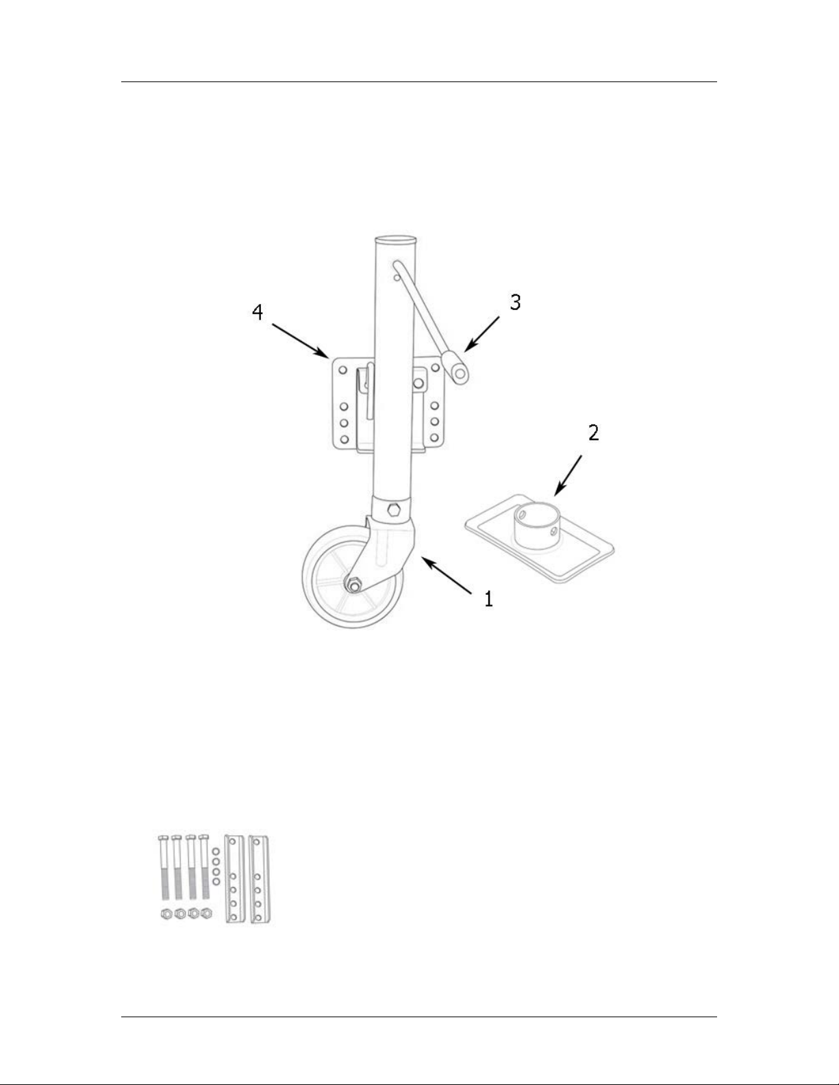
Attach Wheel
Attach the wheel to the fork using the
M12x80 cap screw and M12 lock nut. Lock
in place with the M10x16 cap screw.
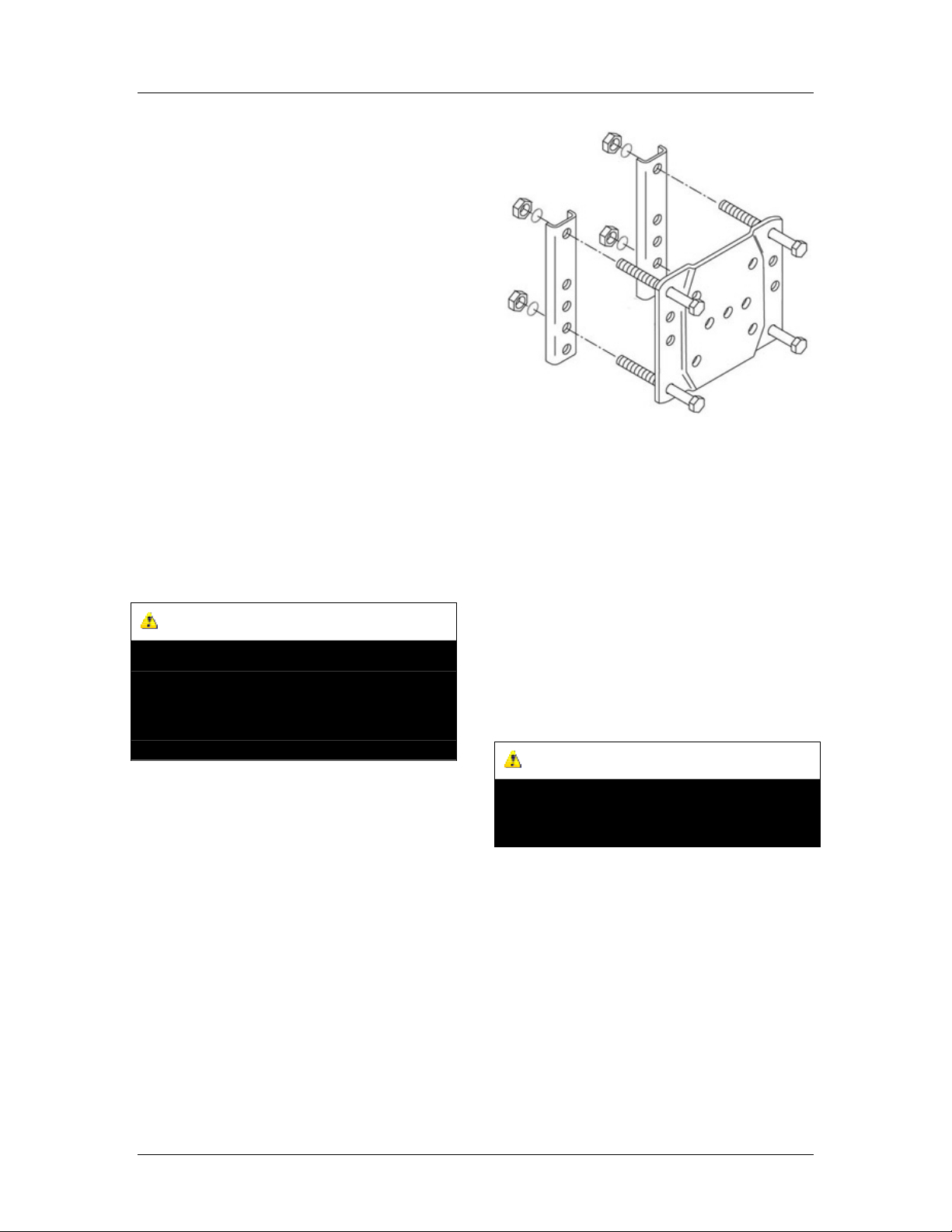
Attach Plate
CAUTION
Properly support the tongue of the trailer to
provide clearance for the jack before installation.
Use chocks to block the trailer to insure it will not
roll during installation.
You will need the following tools to install
the wheels:
14 mm wrench
17 mm wrench
Socket wrench with a 17 mm socket
1. Position the mounting bracket (80005-
013) on the side of the trailer tongue in
the desired mounting position.
2. Position the mounting straps (80005-
11) on the opposite side of the tongue.
3. Insert the cap bolts (80005-012)
through the mounting plate and the
mounting bracket.
4. Secure the bolts with the spring washers
(80005-010) and nuts (80005-009). Do
not tighten the nuts at this point.
5. Inspect the position of the trailer jack.
Use a rubber mallet or hammer with a
block of wood to tap the jack into proper
alignment. Bolts must be at a right angle
to the mounting plates.
6. Tighten the nuts evenly by small
increments to ensure the jack stays in
proper alignment.
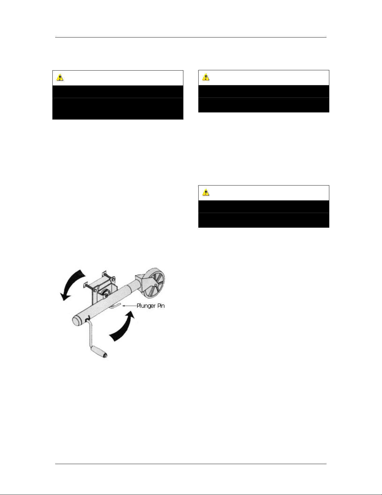
7. Turn the handle (80005-006) in both
directions to test proper operation.
Interchangeable Base
Your trailer jack is equipped with an
interchangeable base. Use the flat foot plate
(80005-033) for stationary storage. Use the
swivel wheel assembly for maneuverability.
CAUTION
DO NOT attempt to change the base with a load
on the jack.
1. Remove the lock nut (80005-026) and
slide the bolt (80005-027) out of the
tube assembly (80005-025).
2. Remove the currently installed base.
3. Insert the foot plate (80005-033) or the
swivel base (80005-028) into the tube
assembly (80005-025) and secure with
the bolt (80005-027).
4. Firmly attach the lock nut (80005-026).
Rev 80005-20131119