ChamSys QuickQ Series Technical manual
ChamSys QuickQ Series Service Document
Page 1 of 17 www.chamsys.co.uk
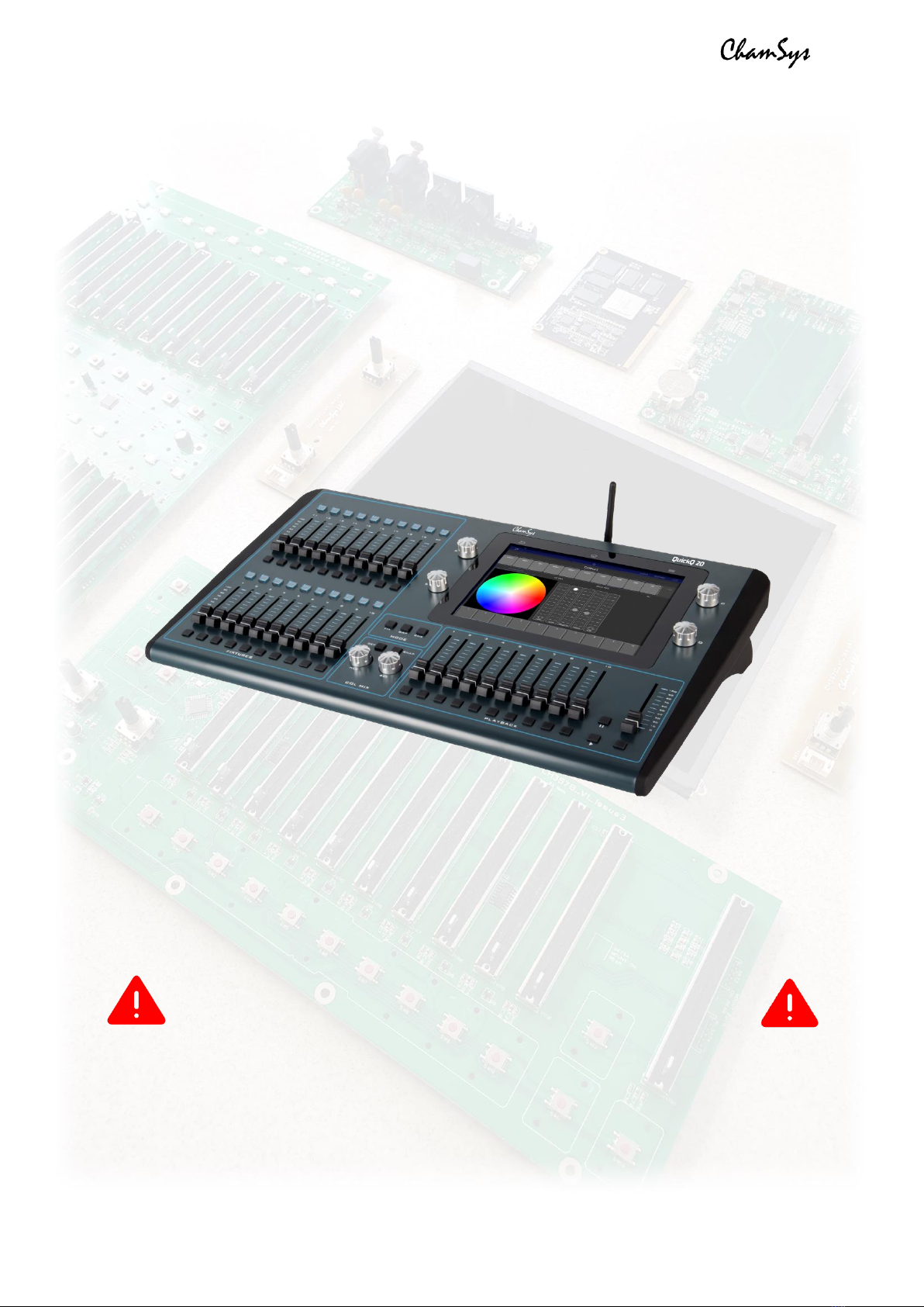
ChamSys QuickQ Series
Service Document
This manual covers all consoles in the ChamSys QuickQ series.
MAINTENANCE SHOULD BE CARRIED OUT BY EXPERIENCED AND
QUALIFIED PERSONNEL ONLY
WARNING –LIVE 240V AC. DISCONNECT MAINS BEFORE
PERFORMING ANY MAINTENANCE
ChamSys QuickQ Series Service Document
Page 2 of 17 www.chamsys.co.uk
Section 1: An overview of the console and all components.
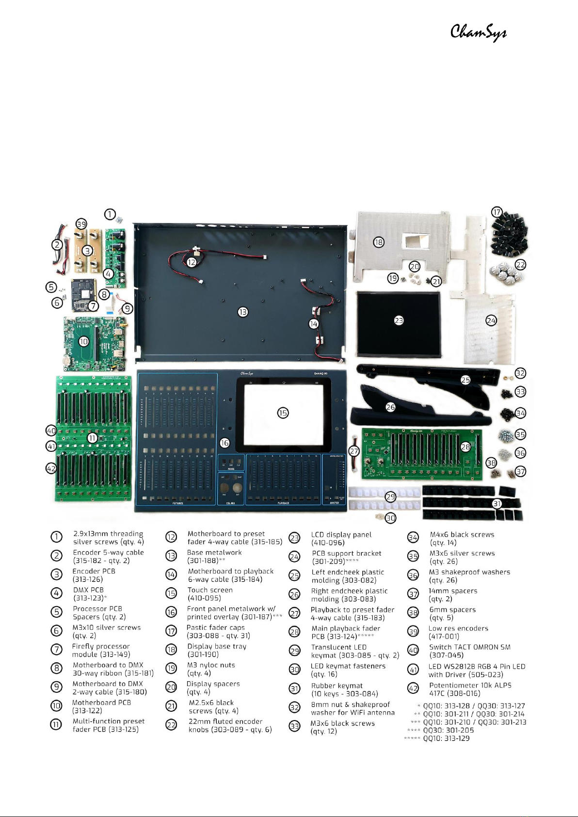
Below is an exploded picture of a QuickQ 20 console, showing all components.
Underneath is a list of all parts and ChamSys part numbers, where applicable.
Note that these parts are for a QuickQ 20 console, as an example. Parts for the QuickQ 10
and QuickQ 30 consoles are similar, in most cases the same. Any differences will be
highlighted with asterisks (*). Quantities of fixings apply only for the QuickQ 20 console.

ChamSys QuickQ Series Service Document
Page 3 of 17 www.chamsys.co.uk
Section 2: Testing to determine faults.
All ChamSys consoles contain built-in hardware tests, including the QuickQ series. To
access these tests on a QuickQ console, follow the steps below.
1. Power on the QuickQ console
2. Enter the Setup window via the menu button (top right - see image below)
3. Navigate to the Update window
4. Once in the Update window, select the ‘Run Startup App’ option
5. Inside the Startup App, select ‘More Options’, then ‘Factory Tests’
Once in the factory test window, use the ‘Set
Product’ option to select the correct console
model (see image, left).
Once you have set the console model, you’ll
then have access to the appropriate tests for
the console. Some tests require specific
testing equipment and cables, but other
tests, such as the tests for front panels can
be run without the need of any extra
equipment.
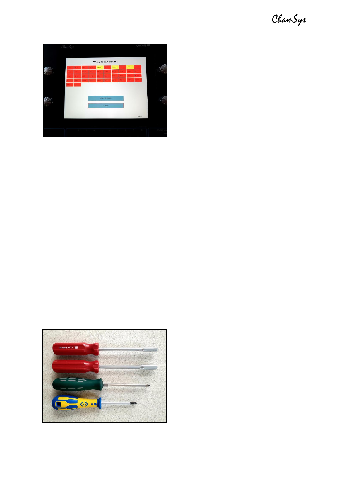
The factory tests for QuickQ are organised by panels and ports. For example, if you
suspect there is a fault with some of the faders on the multi-function preset fader panel,
select the test for this panel to begin testing the faders. Once you select the test, you’ll
see a screen similar to the one pictured below. Items highlighted red are untested, while
yellow items are partially tested, and green items are complete.
ChamSys QuickQ Series Service Document
Page 4 of 17 www.chamsys.co.uk
Faders and encoders are the most likely
parts to wear over time and require
replacing. These can be tested using the
corresponding front panel tests.
Encoders should show positive values when
moved in a clockwise direction, and negative
values when moved anti-clockwise. If mixed
+/- values are shown in each direction, the
encoders will need replacing, as covered in
section 4, below.
Similarly, faders should show positive values only when being moved up, and negative
values only when being moved down. Faders behaving strangely will likely need
replacing, but can also be a sign of other issues.
TIP: When testing faders and encoders, move them slowly, as fast movements can lead
to inaccurate results and it can also be more difficult to observe their behaviour.
When running the test for the multi-function pre-set fader panel, the LEDs will light up in
red, green, blue, and white. Ensure all LEDs are lighting correctly. If not, they may need
replacing, as covered in section 4, below. Note that a whole row of LEDs not working
correctly is usually a fault with a single LED only. For more on this, see section 4.
Section 3: Full disassembly of the console.
Here are instructions for complete disassembly of a QuickQ console. The example is for
a QuickQ 20 console, but the QuickQ 10 and QuickQ 30 consoles are similar, and any
differences will be highlighted. Quantities of screws may vary in some cases, depending
on the console model. Note that in most cases for repairs, only partial disassembly will
be required, by following the relevant steps.
Just 4 tools are required for complete
disassembly of a QuickQ console, as pictured
to the left. From top to bottom, these are:
•5.5mm nut driver*
•8mm nut driver*
•PZ2 screwdriver
•PZ1 screwdriver
*can be substituted with an adjustable spanner
ChamSys QuickQ Series Service Document
Page 5 of 17 www.chamsys.co.uk
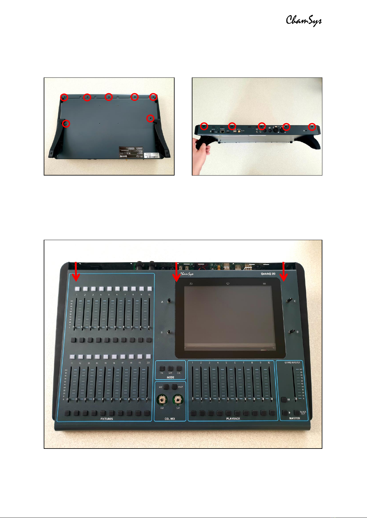
Step one: Remove the M3x6 black screws from the rear and bottom of the console using
a PZ1 screwdriver, as highlighted in the images below. Note that the QuickQ 30 has more
of these screws to remove, but these are found around the same places as the example.
Step two: Remove all fader caps and encoder knobs. These simply pull off with a little
force. If you are carrying out repairs on one panel, remove the caps for this panel only.
Step three: Place the console on a flat surface, face up with the front towards you. Slide
the front panel down towards you, by approximately 1 inch. This can be achieved by
gripping the sides and pushing with your thumbs. See the image below for reference.

ChamSys QuickQ Series Service Document
Page 6 of 17 www.chamsys.co.uk
Step four: Carefully lift the front panel up from the top, leaving the bottom down on the
surface. As you lift the front panel up, look underneath and you will see 2x cables that
need to be disconnected. The first runs from near the top of the preset fader PCB, to the
motherboard. You will need to disconnect this at the fader PCB end, before being able to
lift the front panel up completely. To disconnect this cable, pull it away with some gentle
force, while wiggling the cable, until it comes free. You will now be able to lift the front
panel up to 90 degrees and disconnect the other cable also. See images below.
You should now have the QuickQ
console in two main pieces as pictured,
left. These are:
•The base of the console,
containing the LCD display,
motherboard and DMX PCB.
•The front panel, containing the
playback and preset fader PCBs, the
encoder PCBs (except on a QuickQ 10),
and the touch screen, which is bonded
with the front panel metalwork.
We will continue this guide first with
complete disassembly of the base of
the console. If this does not apply to the
repairs you need to carry out, skip
ahead to the following section on
disassembly of the front panel.
ChamSys QuickQ Series Service Document
Page 7 of 17 www.chamsys.co.uk
Disassembly of the base section of the console:
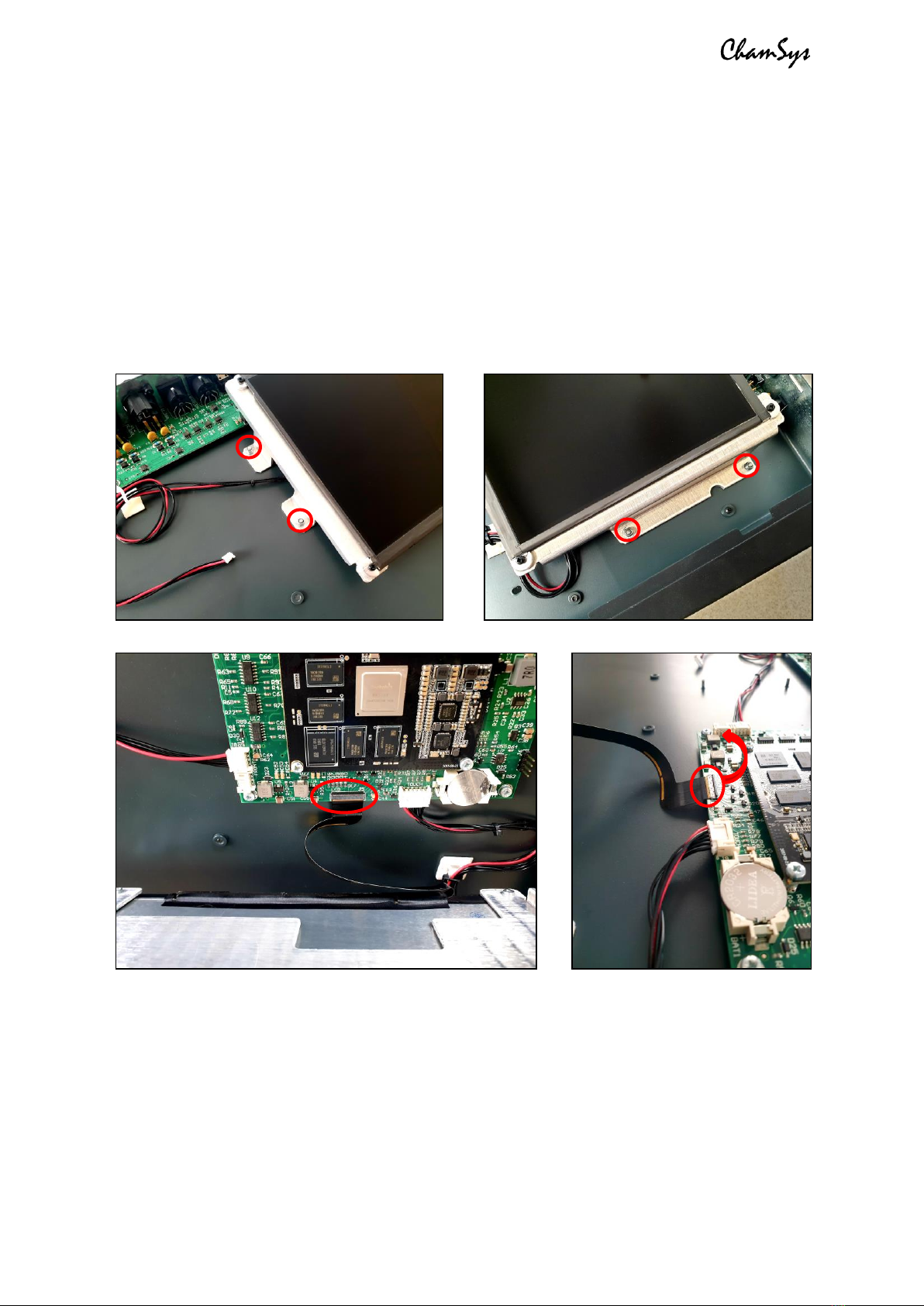
Whether you need to replace the LCD display, motherboard, or DMX PCB, you will always
first need to remove the display to access all parts. This is screwed into the display base
tray and needs to first be removed as a whole unit. To do this, remove the 4x M3 nyloc
nuts from around the base tray using a 5.5mm nut driver or adjustable spanner. Once
the tray is free, carefully lift it up from the top to a 90-degree angle and you will see
where the display is connected to the mother board, as pictured below. To disconnect
this, the tab on the connector must be lifted before the ribbon cable can be removed.
Attempting to remove the cable without first lifting the tab is likely to break the
connector, resulting in this, or possibly the entire motherboard, needing replacing.
Replacing the LCD display: Once the display unit has been disconnected and removed,
you may wish to remove the display itself from the base tray, in order to replace the
display. This is done by removing the 4x M2.5x6 black screws from the four corners of
the display, using a PZ1 screwdriver. Note that there are also spacers that sit between
the display and the base tray, which will come loose when removing the screws. These
will need to be replaced in the correct orientation when re-fitting the display. You can
now remove the display and replace if required.
ChamSys QuickQ Series Service Document
Page 8 of 17 www.chamsys.co.uk
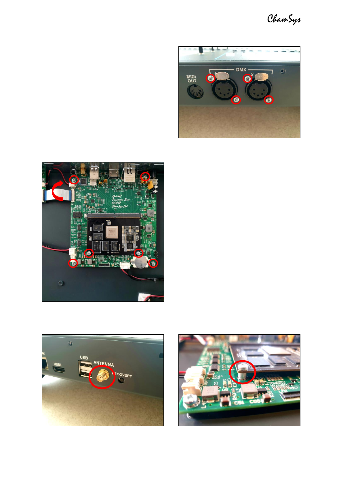
To remove the DMX PCB: First remove the
4x screws from around the DMX ports on
the rear of the console as pictured, right.
Once these are removed, it is recommended
that you first disconnect the PCB, before
removing the final screws. Both the 2-way
cable and the 30-way ribbon cable need to
be removed. The ribbon cable is removed by
first lifting the tab, as with the LCD display
cable. You can then remove the 3x M3x6
screws and shake-proof washers holding the
PCB into the base of the console and remove
the PCB from the console.
To remove the motherboard: First, unscrew
the nut and shake-proof washer securing the
antenna in place from the rear of the
console, as shown in the picture below, left.
This is done using an 8mm nut driver, or
adjustable spanner.
Next, unplug all cables. All cables with
red/black wires can be removed with careful
force while gently wriggling the connector.
The 30-way ribbon cable to the DMX PCB
however must first have the tab on the
connector lifted to free it. Once this is done,
remove the 4x M3x6 screws holding the PCB
into the console base, as well as the 2x
M3x10 screws through the firefly processor
module (see picture, left). Note that when
these two screws are removed, the module will naturally lift to roughly a 45 degree
angle. You will also find 2x spacers between the firefly module and the motherboard,
which will come free once the two screws are removed. See picture below, right.

ChamSys QuickQ Series Service Document
Page 9 of 17 www.chamsys.co.uk
To remove the plastic moulded endcheeks/feet from the console: The final part for
complete disassembly for the base of the console is to remove the endcheeks/feet from
the console. There is one of these on each side, each secured with a total of 7x M4x6
black screws –2x on the base, and 5x on the inside of the chassis. To remove these,
you’ll need to use a PZ2 screwdriver. See the images below for locations of the screws.
Disassembly of the front panel section of the console:
Start by removing the PCB support bracket by removing all M3x6 screws and shake-
proof washers highlighted in the image below, using a PZ1 screwdriver. The QuickQ 10/20
consoles have 5x screws, while the QuickQ 30 has a larger plate with more screws.
ChamSys QuickQ Series Service Document
Page 10 of 17 www.chamsys.co.uk
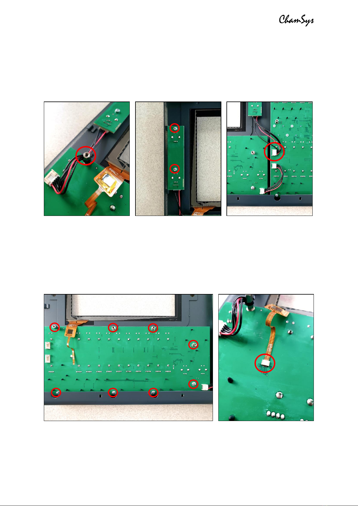
To remove the encoder PCBs: Each of these PCBs is secured in place with 2x M3x6
screws and shake-proof washers, removable with a PZ1 screwdriver. Each PCB is also
connected by one cable, which can be disconnected at either end by pulling with light
force, while wiggling the connector until it comes free. Note that the cable for the left-
hand encoder PCB (when looking from the underside of the front panel) is secured to a
spacer with a cable tie –see the left picture, below. This can be slid off or cut.
To remove the playback fader PCB: First, disconnect the touch screen ribbon cable,
highlighted in the picture below, right. You will also need to disconnect the cables to the
encoder PCB and the preset fader PCB if you have not already done so. Once all cables
are disconnected, remove the 4x M3x6 screws and shake-proof washers using a PZ1
screwdriver, and the 4x spacers using a 5.5mm nut driver or adjustable spanner (all
highlighted in the left picture below). The panel should then be free to be removed.
ChamSys QuickQ Series Service Document
Page 11 of 17 www.chamsys.co.uk
To remove the multi-function preset fader PCB:
First, disconnect the cables running from the preset
fader PCB to the encoder and playback fader PCBs if
you haven’t already done so. You can then remove the
3x M3x6 screws and shake-proof washers using a PZ1
screwdriver, and the 3x spacers using a 5.5mm nut
driver or adjustable spanner (all highlighted in the
picture to the right). The panel should then be free to be
removed.
The QuickQ 30 console has two of these panels, so this
will need to be done once per panel.
To remove and replace the touch glass:
Once all PCBs have been removed from the front panel, you will then be able to replace
the touch glass, if required. The glass is secured to the metalwork with double-sided
tape. To remove the glass, you will first need to heat up the tape. Do this by carefully
using a heat gun on a low speed, keeping it moving around all edges of the glass until
heated. You should now be able to try
to pry the glass away. Be careful as
the glass may be hot, or shatter. If the
glass won’t move, heat it up some
more until it does.
Once the touch glass is removed, clean
the metalwork until all sticky residues
is removed. You can then replace the
touch glass with a new panel, using
new genuine 3M touch tape. Ensure
only genuine 3M tape is used, or the
glass may not stick well enough.
With all disassembly complete, in section 4, we will run through some common issues
that can occur with these consoles, and how to resolve them. If you are experiencing any
issues with a console not covered in the next section, or have any further questions,
for more information.

ChamSys QuickQ Series Service Document
Page 12 of 17 www.chamsys.co.uk
Section 4: Resolving some common issues.
Below are some common issues that can appear on QuickQ consoles and how to solve
these, including replacing faders, encoders, and resolving issues with LEDs.
Replacing faders:
Faders can naturally wear down with use and may end
up needing replacement if noise is being experienced,
or they feel scratchy, or unusually loose. To replace
faders, first remove the relevant PCB from the console,
as per the instructions in section 3.
Start by completely de-soldering the 8 solder joints for
the fader, as highlighted in the image to the right. The
holes must be completely free of solder to allow the
fader to be removed. Once removed, place the new
fader into the holes and solder the connections. We
recommend using high-quality lead-free solder.
Fader part number: 308-016-02
Replacing encoders:
It is common for encoders to wear with use. As
mentioned in section 2, when testing encoders, you
should see positive values only when rotating clockwise
and negative values when rotating anti-clockwise. If
mixed values are experienced in one or both directions,
the encoder will need replacing. To replace an encoder,
first remove the relevant PCB from the console, as per
the instructions in section 3.
Start by completely de-soldering the 5 solder joints for
the encoder, as highlighted in the image to the left. The
holes must be completely free of solder to allow the
fader to be removed. Once removed, place the new
encoder into the holes and solder the connections.
Encoder part number: 417-003
ChamSys QuickQ Series Service Document
Page 13 of 17 www.chamsys.co.uk
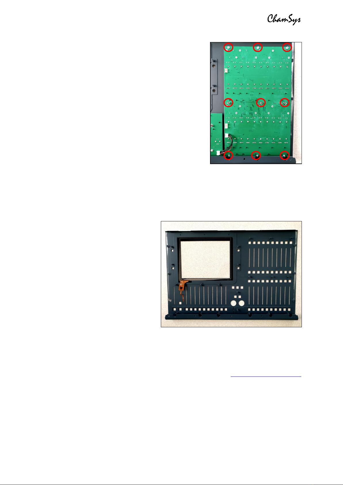
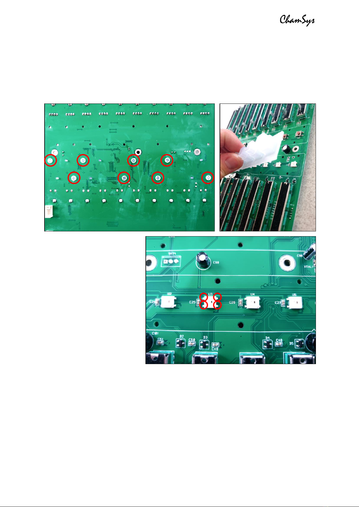
Diagnosing and replacing faulty LEDs:
Usually when issues occur with LEDs, a few or an entire row will stop working, since they
are connected in series. As mentioned in section 2, an entire row of LEDs not working is
usually actually an issue with 1 LED only; either the last LED to the left which is working,
or the first LED to the left which is not working.
To replace LED, first remove
the relevant PCB from the
console, as per the instructions
in section 3. To access the
LEDs, you will first need to
remove the translucent keymat
from the affected row. Each
keymat is secured in place by
8x fasteners, as in the left
picture, above. These fasteners
just pull off with a little force.
To diagnose which LED has the
fault, measure each of the
possible faulty LEDs as
mentioned above, using a meter.
Once the faulty LED has been found, this can be replaced by de-soldering the 4 surface-
mounted solder joints, as highlighted in the image above. Once the faulty LED is
removed, hold the new LED in place and solder the connections.
LED part number: 505-023
ChamSys QuickQ Series Service Document
Page 14 of 17 www.chamsys.co.uk
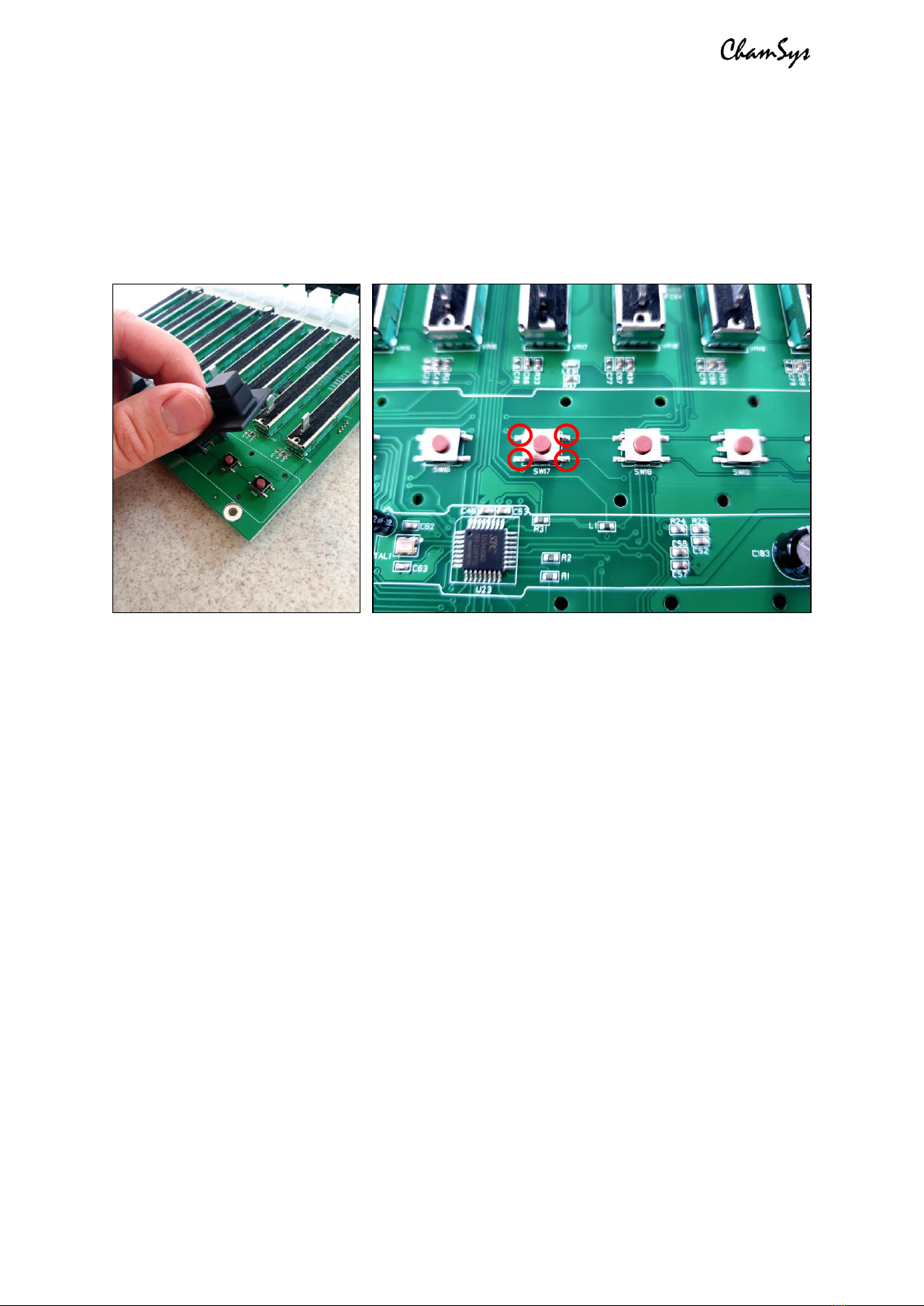
Replacing switches:
To replace switches, first remove the relevant PCB from the console, as per the
instructions in section 3. You will then need to remove the rubber keymat for the row of
switches, which simply pulls off. The faulty switch can then be replaced by de-soldering
the 4 surface-mounted solder joints, as highlighted in the image below, right. Once the
faulty key is removed, hold the new key in place and solder the connections.
Switch part number: 307-045
Section 5: Setting the ID of the multi-function preset fader PCB.
If the multi-function preset fader PCB is replaced (the left-hand fader panel), you may
need to reset the PCB ID. Usually this is programmed as ID1 for QuickQ 10 and 20. For the
QuickQ 30, which has 2 of these PCBs fitted, then left-hand PCB is programmed as ID1,
while the right-hand PCB is programmed as ID2.
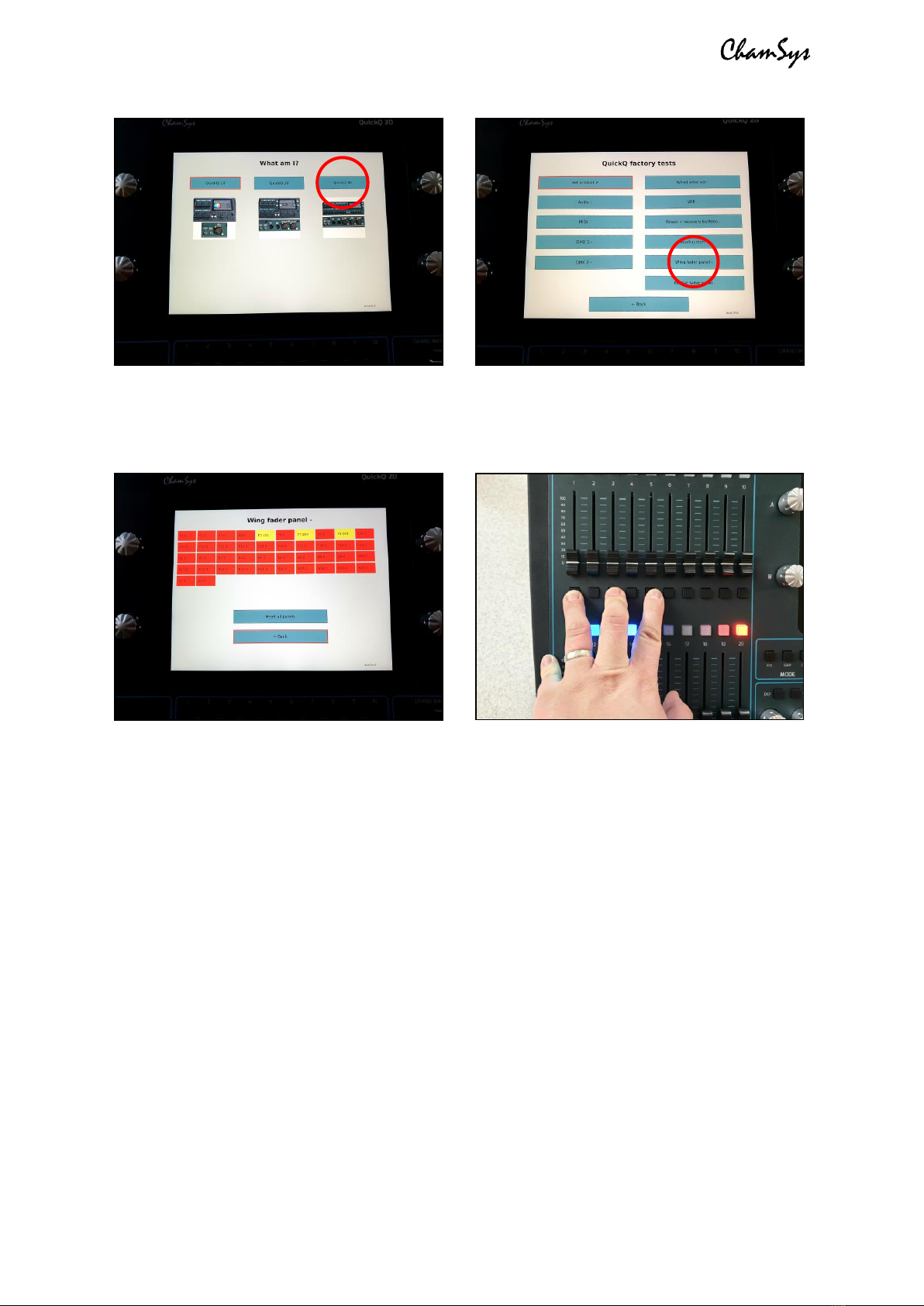
To reprogram the PCB ID:
1. Connect the PCB(s) as normal to the motherboard PCB in the console
2. Access the factory tests via the Startup App (see Section 2)
3. Use the ‘Set Product’ option to select the product as a QuickQ 30 (left pic, below)
4. Next, select the appropriate test for the panel you are reprogramming (right
picture, below). When set as a QuickQ 30, you will see two options here, for the
left and right fader panels. If reprogramming the multi-function faders on a
QuickQ 10, 20 or the left-hand PCB on a QuickQ 30, select the ‘Wing fader panel
left’ option. OR to set the Right-hand fader panel on a QuickQ 30 (ID2), select the
‘Wing fader panel right’ option.
ChamSys QuickQ Series Service Document
Page 15 of 17 www.chamsys.co.uk
5. You should now see the test screen, as shown below, left.
6. Hold down the UPPER fader bank select/flash keys 1, 3 and 5 of the panel you
wish to reprogram as shown below, right.
7. While holding these 3 keys down, press the ‘Reset all panels’ menu option shown
on the touch screen. The PCB will now enter ID selection mode.
8. Using the lower select/flash keys, select the PCB ID. Use key 1 for QuickQ 10,
QuickQ 20, or the left-hand fader panel on a QuickQ 30, or key 2 for the right-
hand fader panel on the QuickQ 30.
9. Press the lower right-hand flash key (the LED should be lit RED above it –see the
right-hand image above) to store the setting.
10. Go back to the main test screen menu and then re-enter the fader panel test to
prove setting has taken correctly.

ChamSys QuickQ Series Service Document
Page 16 of 17 www.chamsys.co.uk
Section 6: Resetting the console.
Some issues can often be solved by soft resetting the console, or even completely
restoring the console to a factory state. Below are how to perform each of these actions.
Soft reset the console via the recovery button:
If the console is unresponsive, the first thing to try would be resetting via the recovery
button on the rear of the console, as seen in the picture below. Hold this button until the
console resets and this should solve the issue.
Reset the console to factory settings:
If software issues persist or are experienced regularly, these may be solvable by
completely resetting the console to a factory state. This can be done by accessing the
Startup app (see section 2), then navigating to More Options > Reset to factory settings.
Here, you’ll be presented with two options: either a full reset, which will also erase all
show data, or reset the settings only, but keep all data. If using the first option, be sure to
back up any required show files first, as these will be permanently deleted.

ChamSys QuickQ Series Service Document
Page 17 of 17 www.chamsys.co.uk
Technical Specifications
QuickQ 10 QuickQ 20 QuickQ 30
Touch Screen 9.7" 9.7" 9.7"
Universes Supported 1 2 4
DMX Outputs 5-Pin XLR 1 2 3
Fixtures Supported 512 1024 2048
Fixture Faders 20 20 40
Bump Buttons Y Y Y
Dedicated
Hue/Saturation
Y Y Y
Attribute Encoders 0 4 4
Master Faders 2 Chase & 1 Cue Stack
10 Multi Function
Playbacks
10 Multi Function
Playbacks
Cue Stacks 1 Multiple Multiple
Dedicated Home
Button Y Y Y
USB Ports 2 2 2
Network 1 x 10/100 Mbps port 1 x 10/100 Mbps port 1 x 10/100 Mbps port
External Monitor 1920 x 1080 HDMI 1920 x 1080 HDMI 1920 x 1080 HDMI
Audio In/Out Mini Jack In/Out Mini Jack In/Out Mini Jack In/Out
sACN Y Y Y
ArtNet Y Y Y
Pathport Y Y Y
OSC N Y Y
MIDI N 5 pin Midi In/Out 5 pin Midi In/Out
MIDI Timecode Support N Y Y
Fixture Types
supported
LEDs and Dimmers
LEDs, Dimmers & Moving
Lights
LEDs, Dimmers & Moving
Lights
Wifi 802.11bgn 2.4G 802.11bgn 2.4G 802.11bgn 2.4G
Size (WDH mm) 525 x 350 x 106 525 x 350 x 106 760 x 350 x 106
Weight 4.7KG 5.2 kg 6.1KG
Power Input 12v DV 12v DV 12v DV
Power Supply External 12V 2amp External 12V 2amp External 12V 2amp
Item code 100-710 100-720 100-730
If you are experiencing any issues with a console that are not covered in this document,
or have any further questions, please contact ChamSys support for more information.
Tel: +44 (0)2380 238 666
Email: support@chamsys.co.uk
Other manuals for QuickQ Series
1
Table of contents
Other ChamSys Dj Equipment manuals


Popular Dj Equipment manuals by other brands


EuroLite
EuroLite Safety Mirrorball 150 cm installation instructions

Chauvet DJ
Chauvet DJ Hurricane Bubble Haze X2 Q6 Quick reference guide

Pixapro
Pixapro LED100B MKIII instruction manual

OmniSistem
OmniSistem Stinger 1 Series User's information guide

Party Light & Sound
Party Light & Sound PARTY-3PACK user manual

USA Dance Floor
USA Dance Floor ILLUMA SQUARE A instruction manual