4A
4. How To Control The Unit
Three ways to operation:
A. Master/Slave operation
B. Easy controller CA-8
C. Universal DMX controller
A. Master/Slave operation
The unit can be linked together in daisy chain as many as you need in master/slave mode to
perform the great built-in pre-programmed lighting shows triggered by music.
In Master/Slave mode refer to the DMX settings below:
Master unit: DMX start address MUST be set to 001. (First DIP switch = ON, all other
are OFF)
Slave units: DMX start address may have any value but NOT 001 (example: set the
first 3 DIP switches to ON)
﹡Dipswitch 2 “ON” has two functions:
1. Perform the built-in pre-programmed by music.
2. Auto mode: Eight Chase(At this mode press dip switch 3 will change the direction of
rotation,press dip switch 4,5,6 will change the speed)
﹡2-light show
Dipswitch 10 ”off” means the unit works normally and “on” means inversion. In order to
create a great light show, you can set dip switch 10 ”on” on any unit that is linking to the
master unit to get contrast movement to the master unit, even if you have two units only.
Dipswitch 10 on the first ( Master ) unit is no use for the 2-light show as it is the master unit
that operates the light show.
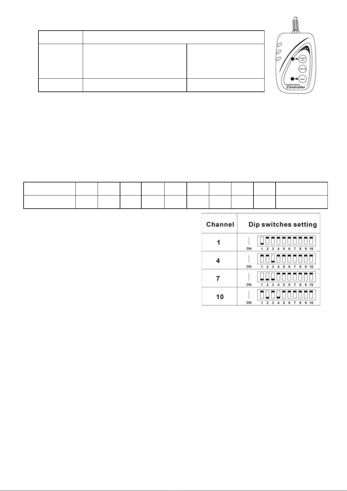
B. Easy Controller (by CA-8)
The easy remote control is used only in master/slave mode. By connecting to the 1/4”
microphone jack of the first unit (its DMX input plug is not used), you will find that the remote
control all the first unit will control all the other units for Stand by, Function and Mode. Built-in
lighting shows triggered by Easy Controller:
5A
Stand by Blackout the unit
Function
1. Synchronous Strobe
2. Two light Strobe
3. Sound Strobe
Rotation Speed
1-8
Mode Strobe (LED OFF) Rotation (LED ON)
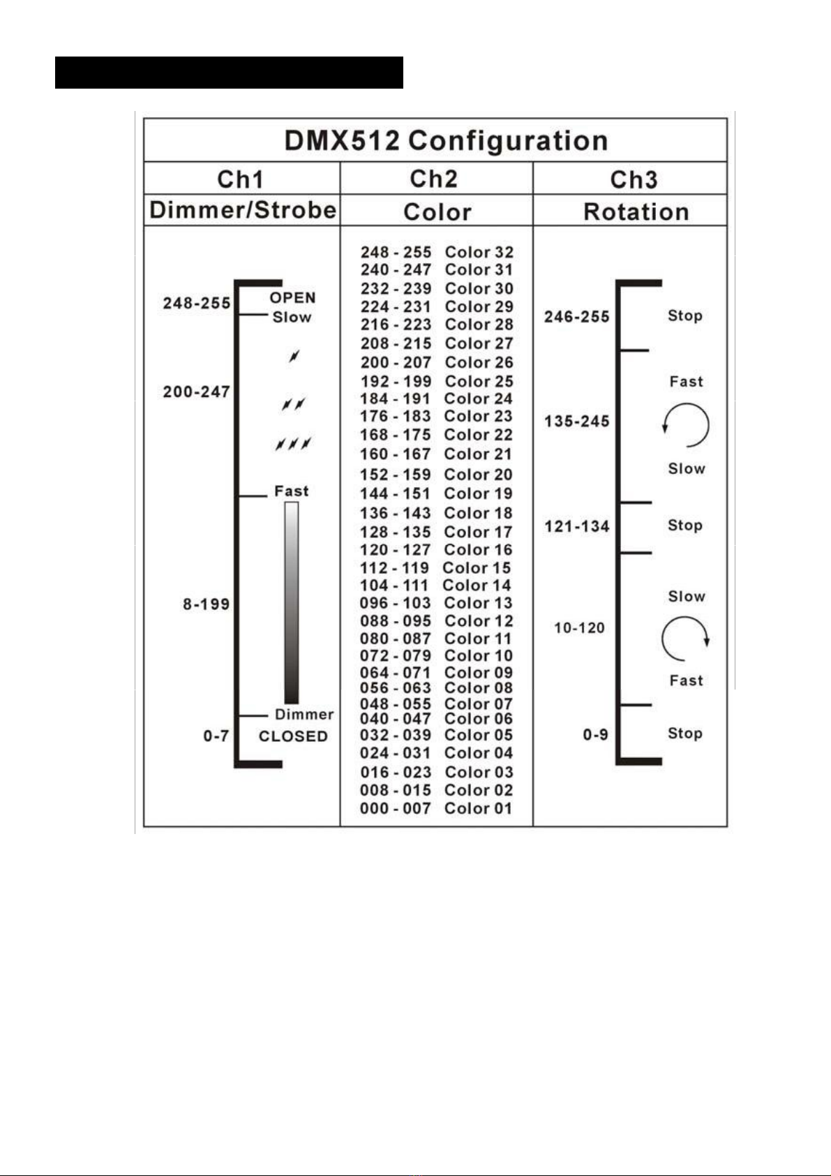
C. Universal DMX controller
When using a universal DMX controller to control the chain of units, you have to set DMX
address by Dip switches from 1 to 9 to make sure all the units will receive its DMX signal.
Please refer to the following diagram to know how to address your DMX 512 system in the
binary code.
DMX 512 Address Chart:
Dip-switches # 1 # 2 # 3 # 4 # 5 # 6 # 7 # 8 # 9 #10
Value 1 2 4 8 16 32 64 128 256 2-light show
• Examples:
Channel 1:dip / on: #1 (=1)
Channel 4:dip / on: #3 (=4)
Channel 7:dip / on: #1, #2, #3 (1+2+4=7)
Channel 10:dip / on: #2, #4 (2+8=10)