manuals.online logo
Brands
  1. Home
  2. •
  3. Brands
  4. •
  5. Channel Vision
  6. •
  7. Keypad
  8. •
  9. Channel Vision DS-Keypad User manual

Channel Vision DS-Keypad User manual

500-280 rev A
www.chann e l v i s i o n . c o m
234 Fischer Avenue, Costa Mesa, California 92626 USA
(714)424-6500 (800)840-0288 (714)424-6510 fax
email: [email protected]
1
Channel Vision Technology will repair or replace any defect in material or
workmanship which occurs during normal use of this product with new or rebuilt
parts, free of charge in the USA, for one year from the date of original purchase.
This is a no hassle warranty with no mail in warranty card needed. This warranty
does not cover damages in shipment, failures caused by other products not
supplied by Channel Vision Technology, or failures due to accident, misuse, abuse,
or alteration of the equipment. This warranty is extended only to the original
purchaser, and a purchase receipt, invoice, or other proof of original purchase date
will be required before warranty repairs are provided.
Mail in service can be obtained during the warranty period by calling (800) 840-
0288 toll free. A Return Authorization number must be obtained in advance and
can be marked on the outside of the shipping carton.
This warranty gives you specific legal rights and you may have other rights (which
vary from state to state). If a problem with this product develops during or after the
warranty period, please contact Channel Vision Technology, your dealer or any
factory-authorized service center.
Channel Vision products are not intended for use in medical, lifesaving, life
sustaining or critical environment applications. Channel Vision customers using or
selling Channel Vision products for use in such applications do so at their own risk
and agree to fully indemnify Channel Vision for any damages resulting from such
improper use or sale.
Specifications:
Power Supply
(typical @25º C)
:
Power Consumption:
Cable Requirements:
Prox. Card Reader Freq.:
Prox. Card Reader Distance:
Internal Relay Type:
Relay Specifications:
Dimensions:
12VDC, 500mA
80mA (idle), 110mA (active)
8-conductor wire, 24AWG or larger
Note: wire carrying current to electric
locks will need to be much thicker.
Consult the electric lock documentation
for its specific wiring requirements.
125kHz
0.39”-0.78” (1-2cm)
Normally Open or Normally Closed
1Amp@12V
4.53” x 2.75” x 1.25”
Specifications subject to change without notice.
DS-Keypad
Entry Access Keypad
0
1
123
456
789
*0#
2
Features:
!
!
!
!
!
Built-in proximity card reader
Register up to 1,000 proximity cards
Non-volatile memory retains setup information after power outages
LED status indicators
Simple setup process - no computer required
The Access Control Keypad is a standalone entry controller
with integrated normally open and normally closed relay contacts. An
integrated proximity card reader allows users to enter without having to
manually key in an access code. Its stainless steel faceplate and blue
backlit keypad buttons make it a rugged and aesthetically pleasing choice
for access control applications.
DS-Keypad
123
456
789
*0#
Orange: Relay Norm. Closed
Power Light: Standby (Red)
Active (Green)
if power light does not
illuminate, immediately disconnect power
supply and check for correct polarity.
IMPORTANT:
External Indicator Light: Active-low (Orange)
System setup requires a system password.
The Default System Password is: 4567
Blue: Relay Common
Green: Relay Norm. Open
White: External Orange LED
Yellow: Door Push button
Gray: Additional Relay
Purple: Alarm Out (Additional Relay)
Black: Ground
Red: +12V
Mounting Screws
Accessories:
7
Using An External Relay
Keypad
Power
Suppy
Keypad
Power
Suppy
Some installations may require a relay that exceeds the current capacity
of the DS-Keypad. For these situations an external relay can be used as
shown below. The DS-Keypad will provide a 12VDC trigger voltage to
activate the relay whenever the door opening function has been activated.
123
456
789
*0#
123
456
789
*0#
Green
Gray
Blue
Black
Black
Red
Red
–
–
+
+
Diode
Diode
Yellow
Simple
push button
Use an external relay to drive an alarm system. When the tamper switch
is depressed there will be no voltage driving the relay. If the tamper switch
is released, then there will be 12VDC between the Gray and Red wires
which will activate the relay.
12VDC
External Relay
12VDC
External Relay
N.O.
N.O.
N.C.
N.C.
Com.
Com.
6
Fail-Secure
Lock (N.O.)
Fail-Safe
Lock (N.C.)
Controlling Electric Locks
Strike
Power
Supply
Strike
Power
Supply
Keypad
Power
Suppy
Keypad
Power
Suppy
The DS-Keypad contains both Normally Open and Normally Closed relay
contacts allowing it be used for either “fail-safe”or “fail-secure”lock
mechanisms. Fail-secure locks remain locked when the power is off and
unlock when power is applied to the mechanism. Of course it is still
possible to manually open the lock from the inside of the building. Most
electric locks are fail-secure.
Fail-safe locks require constant power to remain locked. They are
unlocked in the absence of power.
123
456
789
*0#
123
456
789
*0#
Blue
Blue
Diode
Diode
Green
Orange
Yellow
Yellow
Black
Black
Red
Red
Simple
push button
Simple
push button
–
–
–
–
+
+
+
+
Use this diagram for any lock that requires a Normally Open control
contact.
Note: the simple push button wiring shown below is optional and can be
omitted.
Use this diagram for any lock that requires a Normally Closed control
contact, such as electromagnetic locks.
3
Installation
Tamper switch - If using the tamper switch
feature, this must remain depressed when
the keypad is installed.
Align keypad with box as shown and
secure it with the mounting screws.
(Rear View)
#
0
*
9
8
7
6
5
4
123
The DS-Keypad installs in a standard 1-gang electrical box as shown
below. If the anti-tamper switch setting is turned on, be sure that the tamper
switch is depressed against the back of the electrical box when the keypad
is installed. See programming pages for information on the anti-tamper
settings.
4
Programming
When programming the “#”key is used as the Confirmation or “Enter”key.
In most cases “*”is used to clear an entry or exit a process.
Delete a Proximity Card
Press:
System Reaction:
Press:
System Reaction:
Multiple Beeps
* # [system password] #
One beep
2 [enter the 6-digit card number]
One beep (Card deleted successfully)
signals an error! - Re-enter the 6-digit number
Press:
System Reaction:
*
One beep (Process completed)
Register One Proximity Card
Press:
System Reaction:
Press:
System Reaction:
Three Beeps
* # [system password] #
One beep
1 [enter the 6-digit card number]
One beep (Card registered successfully)
signals an error! - Re-enter the 6-digit number
Note: To exit without changing the setting, *Press:
Change the 8 user passwords
Press:
System Reaction:
Press:
Press:
System Reaction:
* # [system password] #
One beep
3 [enter 1-8 (example:”1”for the first password, “2”for the second...)]
[enter the 4-digit password]
One beep (Password changed successfully)
Optional: [enter 1-8 to change another password] [enter 4-digit password]
Press:
System Reaction:
*
One beep (Process completed)
Set Door Strike Time Duration
Press:
System Reaction:
Press: 4
System Reaction:
* # [system password] #
One beep
[enter the 2-digit time duration in seconds (01-99)]
One beep (Time duration set successfully)
Press:
System Reaction:
Note: To exit without changing the setting, *
One beep (Exit programming)
Programming (continued)
5
Opening the Door Lock with a System Password
Press:
System Reaction:
* # [system password] # 0 0
One beep, power light turns green and door is unlocked
Opening the Door Lock with a User Password
Press:
System Reaction:
[user password]
One beep, power light turns green and door is unlocked
Changing the System Password
Press:
System Reaction:
Press:
System Reaction:
Press:
Press:
System Reaction:
* # [system password] #
One beep
8 [enter new 4-digit system password] #
One beep
[re-enter new 4-digit system password for confirmation]
Note: If confirmation password didn’t match, you’ll hear repeated
beeps, and the system will exit the process.
If no beeps are heard, then continue.
#
Two Beeps (the new password has been saved)
Change Anti-Tamper Switch Setting: 0=ON 1=OFF
Press:
System Reaction:
Press:
System Reaction:
Press:
* # [system password] #
One beep
7 [enter the desired anti-tamper mode, 0=On, 1=Off]
One beep (Anti-Tamper mode has been set)
Note: To exit without changing the setting, *
Batch Registration: Registering multiple cards in series
Press:
System Reaction:
Press:
System Reaction:
* # [system password] #
One beep
6 [enter the 6-digit card number] of cards using 4
digits
One beep (Cards are now registered)
[enter number
]
Setting Identification Access Control Modes
There are 4 possible modes
Enter 4-digit password
* # [system password] #
One beep
5 [enter the mode (1-4)]
One beep (The mode has been set)
Mode 1:
Press:
System Reaction:
Press:
System Reaction:
Mode 2:
Mode 3: AND
Mode 4: OR
Press:
Use Proximity card
Enter 4-digit password use proximity card
To select a mode:
Note: To exit without changing the setting, *

Other Channel Vision Keypad manuals

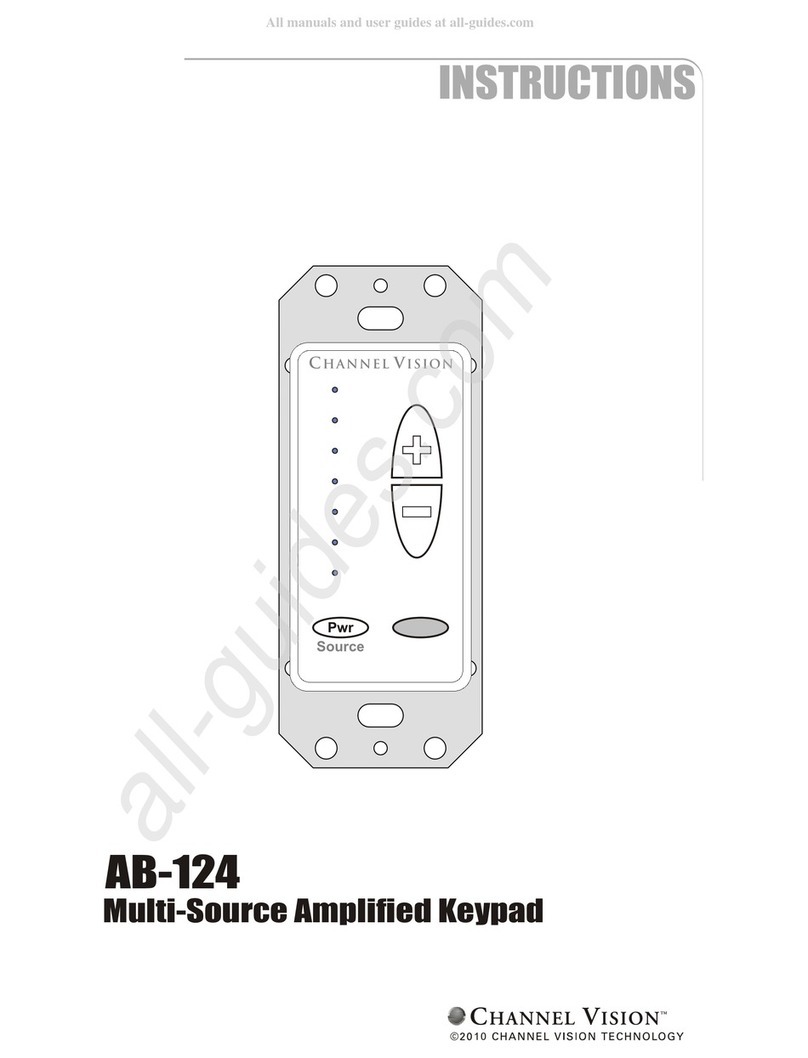
Channel Vision AB-124 User manual

Channel Vision

Channel Vision AB-124 User manual

Channel Vision A0125 User manual

Channel Vision

Channel Vision A0125 User manual

Channel Vision A0127 User manual

Channel Vision

Channel Vision A0127 User manual

Channel Vision AB-134 ABUS User manual

Channel Vision

Channel Vision AB-134 ABUS User manual

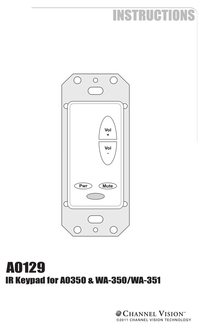
Channel Vision A0129 User manual

Channel Vision

Channel Vision A0129 User manual

Channel Vision A0129 User manual

Channel Vision

Channel Vision A0129 User manual

Channel Vision A0127 User manual

Channel Vision

Channel Vision A0127 User manual

Channel Vision A0127W User manual

Channel Vision

Channel Vision A0127W User manual

Channel Vision AB-124 User manual

Channel Vision

Channel Vision AB-124 User manual

Popular Keypad manuals by other brands

AMX Metreau MET-13 datasheet

AMX

AMX Metreau MET-13 datasheet

Access security product KP-KR3 user manual

Access security product

Access security product KP-KR3 user manual

Sentex Sentex MINI-KEY datasheet

Sentex

Sentex Sentex MINI-KEY datasheet

Digital Security Controls Partner PKP-ICON instructions

Digital Security Controls

Digital Security Controls Partner PKP-ICON instructions

Radio Shack 49-454 owner's manual

Radio Shack

Radio Shack 49-454 owner's manual

Nerival NED-2024 user manual

Nerival

Nerival NED-2024 user manual

Unitech K19 Specifications

Unitech

Unitech K19 Specifications

DSC LCD5501Z Using

DSC

DSC LCD5501Z Using

Eldes EKB2 user manual

Eldes

Eldes EKB2 user manual

HAI 54A00-1 manual

HAI

HAI 54A00-1 manual

Panasonic KX-HNK101AZ operating instructions

Panasonic

Panasonic KX-HNK101AZ operating instructions

lmp NexGen Keypad WKP-803 quick start guide

lmp

lmp NexGen Keypad WKP-803 quick start guide

Satel INT-TSG2 user manual

Satel

Satel INT-TSG2 user manual

GSC 180 Series Handbook

GSC

GSC 180 Series Handbook

Climax KP-15 manual

Climax

Climax KP-15 manual

Rosslare AC-Q4 Series instruction manual

Rosslare

Rosslare AC-Q4 Series instruction manual

Magellan K32IRF installation guide

Magellan

Magellan K32IRF installation guide

Inner Range Integriti Elite user manual

Inner Range

Inner Range Integriti Elite user manual

manuals.online logo
manuals.online logoBrands
  • About & Mission
  • Contact us
  • Privacy Policy
  • Terms and Conditions

Copyright 2025 Manuals.Online. All Rights Reserved.