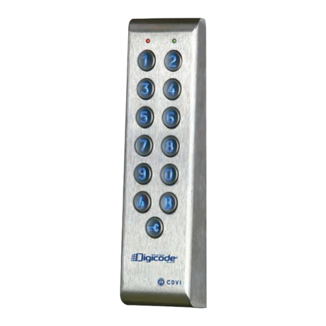
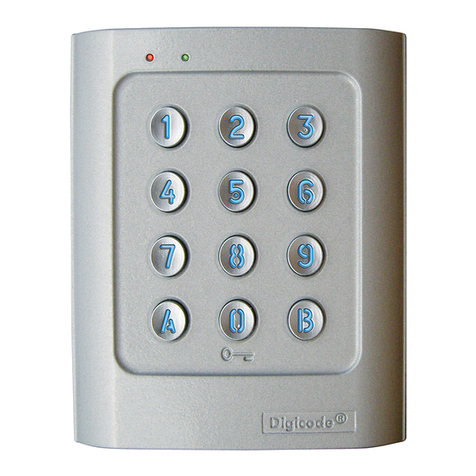
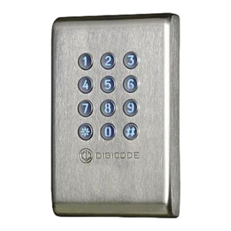
CDVI DC100E User manual

Rev 10/2005 G0301FR0235V01
1
ze
MOUNTING KIT
Qty
Description
Schéma
1
M5 TORX® spanner
1
05D 680K varistor
Dimensions: - Face plate: 200 x 120 x 16 (mm)
- Back casing: 170 x 95 x 35 (mm)
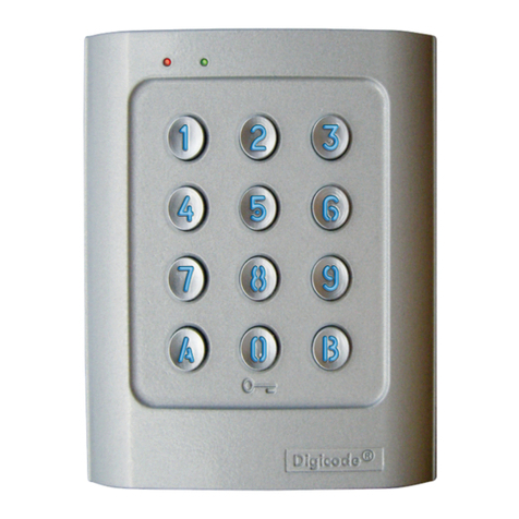
DC100E
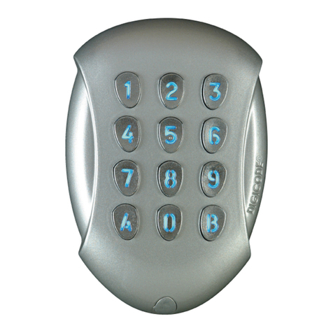
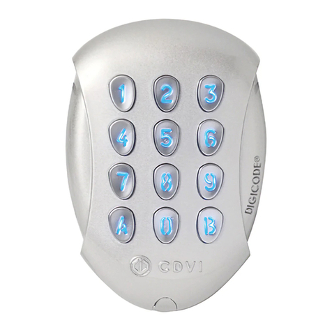
BACK-LIT KEYS KEYPAD
100 USER CODES – FLUSH MOUNT
The DC100E keypad exists also in 2 and 3 relay outputs (DC100E2R, DC100E3R). Refer to page 9 of
this manual for information on 2and 3 relay outputs.
The visual feedback with the green and red LED’s is always active. It is possible to activate the
audible feedback by putting ST1 jumper on (see page 6).
Rating
IP
54
INSTALLATION

Rev 10/2005 G0301FR0235V01
2
I. PRODUCT INFORMATION
A. Technical Features (1 relay output)
Input voltage 12V to 24 VAC
12V to 48 VDC
12-digit backlit keys keypad
Visual feedback (Green and Red LED’s)
EPROM memory storage
100 user codes programmable in 4 to 6-digit code lengh
1 relay output N/O and N/C contact 8A @ 250V
Master code programmable in 4 to 6-digit code lengh
Audible feedback
1 request-to-exit input
P2 jumper: Reset to default master code and delete all user codes
P3 jumper: User code modification by user active
B. Factory Default Values
Back-lit time: 10 seconds
Time relay output: 1 second
Code lengh: 5-digit
Master Code: 12345
Programming mode time: 120 seconds
Sub master code for user code modification by user: A and B
Red LEDS’ lights on when keypad is powered.
C. Audible Feedback
1 short beep Keypad powered
1 long beep Programming validated and relay activated
2 short beeps Enter or Exit from programming
4 short beeps Data computing error
D. Code length
All the keypad keys can be used to program a code.
The master code and the Pin code can be in 4 to 6-digits.
The master code CAN NOT be used as a user code.
Codes 000000, 00000 and 0000 can only be used to delete a user code. To delete a User Code
enter the user number (location number) then enter 0000 if the code length is in 4-digit format,
enter 00000 if the code length is in 5-digit format.
E. Request-to-Exit Input
This normally open loop that operates upon activation relay 1 (DC100E, DC100E2R or DC100E3R) or
relay 2 (DC100E 2 or 3 relay version). This feature is especially useful when controlling a lock.
P1 input activates relay 1 (the time output is programmable).
H1 input can be used with a timer to allow free access by pressing on any key from the keypad. If
the timer contact is open then the free access is deactivated. If the timer is closed then the free
access is activated.
H2 input can be used with a timer to allow free access by pressing on the push button.
F. Current Draw (keypad only)
12V AC: 20 mA in rest, 100 mA max when all 3 relays are energized
24V AC: 10 mA in rest, 50 mA max when all 3 relays are energized

Rev 10/2005 G0301FR0235V01
3
II. PROGRAMMING
A. Erase Keypad Memory / Reset Keypad to Factory Default Values
1. Enter the master code twice (12345 default value master code).
2 beeps are emitted to confirm entry in programming mode.
2. Press A6. The green LED’s lights on during 1 second. Press on A and B to start the reset. The LED’s
lights on solid green. Wait until the green LED’s lights off. The reset is then completed when the red
LED’s lights on and then lights off.
The keypad exits from programming mode and the default values are restored.
OR
1. Cut the power off the keypad. Put P2 jumper.
2. Power the keypad. The green LED’s lights on. Wait a few seconds, one beep is emitted. The green
LED’s lights off. Remove P2 jumper.
3. The keypad is set to the default values.
B. Programming the Code Length
1. Enter the master code twice (12345 default value master code). The red LED’s light on to confirm
entry in programming mode.
2. Press A4 to program the code length. The green LED’s light on during 1 second. Press 4 for a 4-
digit code, press 5 for a 5-digit code or press 6 for a 6-digit code. The green LED’s light on for 1
second to confirm the new code length.
3. Press A5 to program the master code. The green LED’s light on during 1 second. Enter the 4, 5 or
6-digit new master code. The green LED’s light on during 1 second to confirm the new master
code.
4. Press B to exit from programming mode. The red LED’s light off to confirm that the keypad is in
stand-by operating mode.
Red LED’s flashing time indicates a data computing error.
Master code or user code: 12369 Master code or user code: 12369
Changing to a 4-digit code: Enter 2369 Changing to a 6-digit code: Enter 012369
Set the code length first and then program the new master code.
C. Programming a New Master Code
1. Enter the master code twice (12345 default value master code). The red LED’s light on to confirm
entry in programming mode.
2. Press A5 to program the master code. The green LED’s light on during 1 second. Enter the 4, 5 or
6-digit new master code. The green LED’s light on during 1 second to confirm the new master
code.
3. Press B to exit from programming mode. The red LED’s light off to confirm that the keypad is in
stand-by operating mode.
A6
P2
A4
A5

Rev 10/2005 G0301FR0235V01
4
D. ADDING, CHANGING OR DELETING A USER CODE
Group 1: from user number 00 to user number 99 activate relay 1
1. Enter the master code twice (12345 default value master code). The red LED’s light on to confirm
entry in programming mode.
•To add a user code:
2. Enter the user number (00 to 99). If the user number is empty the green LED’s light on during 1
second, enter the 4, 5 or 6-digit user code. If the user number is already programmed, the red LED’s
flash 4 times.
To CHANGE a user code enter the user number, the red LED’s flash 4 times, enter the 4, 5 or 6-digit
user code.
To DELETING a user code enter the user code (location) and then enter 000000 for a 6-digit code,
00000 for a 5-digit code or 0000 for a 4-digit code.
3. Press B to exit from programming mode. The red LED’s light off to confirm that the keypad is in
stand-by operating mode.
User Code List
00 25 50 75
01 26 51 76
02 27 52 77
03 28 53 78
04 29 54 79
05 30 55 80
06 31 56 81
07 32 57 82
08 33 58 83
09 34 59 84
10 35 60 85
11 36 61 86
12 37 62 87
13 38 63 88
14 39 64 89
15 40 65 90
16 41 66 91
17 42 67 92
18 43 68 93
19 44 69 94
20 45 70 95
21 46 71 96
22 47 72 97
23 48 73 98
24 49 74 99
Master Code Master Code
Red LED’s light
on
00
to
99

Rev 10/2005 G0301FR0235V01
5
E. Programming the Time Outputs
Enter the master code twice (12345 default value master code). The red LED’s light on to confirm
entry in programming mode.
2. Press A0 to program the key-in keypad time and the backlit keys time. The green LED’s light
during 1 second. Enter the time in second – 10 for 10 seconds up to 99 for 99 seconds. For
permanent backlit enter 00. The green LED’s light on during 1 second to confirm the time
validation.
3. Press A1 to program the time relay output. The green LED’s light on during 1 second.
Enter the time in seconds – 01 for 1 second up to 99 for 99 seconds. Enter 00 for a toggled output.
The green LED’s light on during 1 second to validate the time programmed.
4. Press B to exit from programming mode. The red LED’s light off to confirm that the keypad is in
stand-by operating mode.
Red LED’s flashing 4 times indicates a data computing error.
F. Reset Master Code to Factory Default Value
Place the jumper on P2 in the back of the keypad. The green LED’s light on and one beep is emitted.
Wait for the green LED’s to light off. Remove jumper from P2. The master code is reset to default
setting 123456 in 6-digit code, 12345 in 5-digit code or 1234 in 4-digit code.
G. Enable/Disable user code modification by user
The Sub Master code allows the user to change its own code without having to enter in programming
mode. For security reasons the code need to be changed periodically. This feature makes it easier
and faster for the user to change its user code.
Place the jumper on P3 to enable user to reprogram its own user code.
Remove the jumper from P3 to disable the user to reprogram its own code.
1. Enter the old user code. The relay is activated and the green LED’s light on.
2. Enter immediately the 2-digit sub master code (A and B Factory Default Value).
The red LED’s light on.
3. Enter the new user code. The green LED’s light on during 1 second, the new user code is
programmed. The red LED’s light off.
4. Enter the new user code to verify.
H. Programming a Sub Master Code
1. Enter the master code twice (12345 default value master code).
The red LED’s light on to confirm entry in programming mode.
2. Press A7 to enter in sub master code menu. The green LED’s light on during 1 second. Enter the
new sub master code. The green LED’s light on during 1 second to confirm programming of the
new sub master code.
3. Press B to exit from programming. The red LED’s light off to confirm exit from programming.
A0
A1
A7
P3

Rev 10/2005 G0301FR0235V01
6
Wiring Diagram DC100E: 1 relay output
V : Varistor
Terminals
Description
V Input Voltage 12 to 24VAC or 12 to 48VDC
P1 Request-to-exit input relay 1
M Common input for P1 and H1
H1 Request-to-Enter Input from 0 digit key
(Timed with a timer)
R1 N/C contact relay 1
C1 Common relay 1
T1 N/O contact relay 1
M Common request-to-enter from Push Button
H2 Request-to-Enter input with Push Button
(Timed with a timer)
This device comes with a varistor.
The varistor must be connected on the strike terminal (electromagnet…) operated
by the device.
If this product operates more than one strike, each lock should have a varistor.
The varistor controls the overload produced by the strike coil – back emf.
It is recommended to use a separate power supply when using a Shear Lock
Magnet.
EM lock / Strike fail safe
P2: Reset
P3: Enable/disable user code
modification by user
ST1: Audible feedback jumper
Remove to disable audible
feedback
P1 H1
RL1
P3
ST1
V V P1 M H1 C3 T3 R2 C2 T2 R1 C1 T1
V
Strike
fail
secure
230V
2
P2
M
H2
Blue
+ -
230V Input voltage
12 to 24 VAC
or 12 to 48 VDC 2
Supply Voltage for
the Lock
V

Rev 10/2005 G0301FR0235V01
7
Wiring Diagram DC100E2R and DC100E3R : 2 and 3 relay outputs
V : Varistor
Terminals
Description
V Input voltage 12 to 24VAC or 12 to 48 VDC
P1 Relay 1 Request-to-Exit input
M Common input for P1 and H1
H1 Request-to-Enter Input from 0 digit key
(Timed with a timer)
C3 Relay 3 common
T3 Relay 3 N/O contact
R2 Relay 2 N/C contact
C2 Relay 2 common
T2 Relay 2 N/O contact
R1 Relay 1 N/C contact
C1 Relay 1 common
T1 Relay 1 N/O contact
M Request-to-Enter input (Push button)
(Timed with a timer)
H2 Request-to-Enter input with Push Button
(Timed with a timer)
EM
lock
/
Strike
fail
safe
This device comes with a varistor.
The varistor must be connected on the strike terminal (electromagnet…) operated
by the device.
If this product operates more than one strike, each lock should have a varistor.
The varistor controls the overload produced by the strike coil – back emf.
It is recommended to use a separate power supply when using a Shear Lock
Magnet.
P1
H1
RL1
P3
ST1
V V P1 M H1 C3 T3 R2 C2 T2 R1 C1 T1
V
Strike Fail Secure
230V
2
P2
RL2
RL3
M
H2
Blue
+ -
230V Input voltage
12 to 24 VAC
or 12 to 48 VDC 2
Supply Voltage for
the Lock
V
P2: Reset
P3: Enable/disable user code
modification by user
ST1: Audible feedback jumper
Remove to disable audible
feedback

Rev 10/2005 G0301FR0235V01
8
I. Enable/Disable Audible Feedback
The audible feedback is always enabled in programming mode or when the relay is energized.
To ENABLE the audible feedback at the press of any key:
1. Enter the master code twice (12345 default value master code).
The red LED’s light on to confirm entry in programming mode.
2. Press AA. One beep is emitted. Enter 1 to ENABLE the audible feedback at the press of any digit
key, 1 beep is emitted to confirm the new set up.
To DISABLE the audible feedback at the press of any key:
3. Press AA. One beep is emitted. Enter 0 to DISABLE the audible feedback at the press of any digit
key, 1 beep is emitted to confirm the new set up.
4. Press B to exit from programming. 2 beeps are emitted.
J. Additional Programming DC100E2R and DC100E3R (2 and 3 relay outputs)
DC100E2R 2 relay outputs: 2 relays N/O and N/C contacts 8A @ 250V~
Group 1: From user number (location) 00 to user number 59, relay 1
Group 2: From user number (location) 60 to user number 99, relay 2
Output time for relay 2 Press A2 Programming a new sub master code Press A8 (Default 1 & 3)
DC100E3R 3 relay outputs: 2 relays N/O and N/C contacts 8A @ 250V~
And 1 relay N/O contact T 6A @ 250V ~
Group 1: user number (location) 00 to user number 59, relay 1
Group 2: user number (location) 60 to user number 79, relay 2
Group 3: user number (location) 80 to user number 99, relay 3
Output time for relay 3 Press A3 Programming a new sub master code Press A9 (Default 4 & 6)
A2
A8
A3
A9
AA

Rev 10/2005 G0301FR0235V01
9
DC100 Mounting Instructions
Prepare a cavity in the wall (170H x 95L x 35P) to mount the
back casing of the DC100E and drill a home for the cable.
Seal the back box and make sure to flush mounted it with
the wall.
After connecting the cable to the DC100E keypad, test a
user code the push button and make sure the LED’s light
on, as well as the buzzer is working. Place the DC100E
keypad on the back box.
Tighten the screw at the bottom of the keypad with the
spanner (TORX® spanner for M5 screw).
1
2
3
4
1
2
3
4

Rev 10/2005 G0301FR0235V01
10

Rev 10/2005 G0301FR0235V01
11
Template
Scale 1:1
Table of contents
Other CDVI Keypad manuals

CDVI
CDVI GALEO/W User manual

CDVI
CDVI CAASE User manual

CDVI
CDVI Digicode Series User manual

CDVI
CDVI GALEO 4.0 - Bluetooth User manual

CDVI
CDVI PROFIL100EINT User manual

CDVI
CDVI GALEO BT User manual

CDVI
CDVI DGA User manual

CDVI
CDVI KCIENSBP User manual

CDVI
CDVI KCIEN User manual

CDVI
CDVI Galeo User manual

CDVI
CDVI Krypto K3 Instruction Manual

CDVI
CDVI PROFIL100EINT User manual

CDVI
CDVI Galeo User manual

CDVI
CDVI C2R User manual

CDVI
CDVI GALEO/W User manual

CDVI
CDVI DGA User manual

CDVI
CDVI Galeo User manual

CDVI
CDVI GALEO 4.0 - Bluetooth User manual

CDVI
CDVI GALEOR User manual

CDVI
CDVI Digicode PROFIL100EC User manual