manuals.online logo
Brands
  1. Home
  2. •
  3. Brands
  4. •
  5. Chapin
  6. •
  7. Paint Sprayer
  8. •
  9. Chapin 97300 Installation instructions

Chapin 97300 Installation instructions

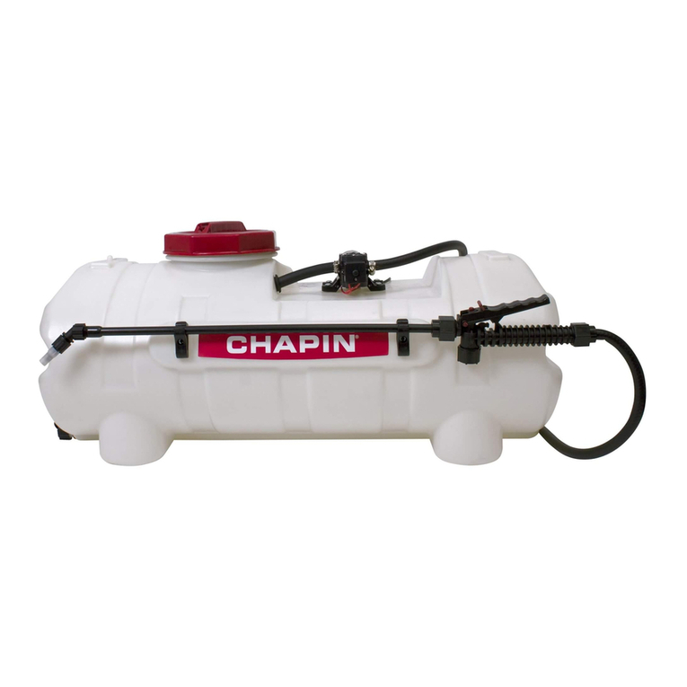
Assembly /Operation Instructions /Parts
|ll(lIlEl#913llll
15 lillllllll
"Mllllil#‘These snraiiers are ilesiuneiltn he attaeheil to astable surface.
25 liallnn
AWARNING A—OPERATION
-The pumping system draws solution from the tank, through the
Careruny Read These rnsrrucrrorrs Berore use strainer and to the pump. The pump forces the solution under
pressure to the spray wand.
25 &15 GAL. DELUXE SPOT SPRAYER Th h
epump as apressure switch which will shut the pump off
-Polyethylene Tank -15 Ft. of 3/8" Hose Whe" "'ea°he$ 6° PS‘-
'12 V0“ Diaphragm Pump 'Pressure Gauge Pressure may be regulated by opening or closing the bypass
'2-2 G-P-M 'Adjusrame Pressure Range valve located on the top of the tank. The more it is opened the
'Lever Handgun (0450 Psr Max-) lower the pressure will be.
ARegularly inspect the suction supply screen on the inside of
—- GENERAL |NFORMAT|ON the tank. Flush with water to clear any accumulated debris.
The purpose of this manual is to assist you in assembling,
operating and maintaining your lawn and garden sprayer. _AFTER SPRAY|NG
Please read it carefully as it furnishes information which Aeruse umes -
-.prayer part way with water. Start the sprayer and
rgrrregiignyou achreve years or dependabie rroume rree allow clear water to be pumped through the plumbing system
p'and out through the spray-wand.
_WARRANTY /PARTS /SERV|CE Rell the tank about halffull with plain water and use achemical
neutralizer such as Nutra-Sol® or equivalent and repeat
Products are warranted for one year fr0m date of purchage cleaning instructions. Flush the entire sprayer with the neutral-
against manufacturer or workmanship defects izing agent. Follow the chemical'manufacturer‘s disposal
instructions of all wash or rinsing water.
Your authorized dealer is the best source of replacement
rt d.... .
pa san service. To obtain prompt, efficient service, always
remember to give the following information: WINTER STORAGE
1Correct part descri non and an number Drain all water and chemical out of sprayer paying special
'p p 'attention to pump and valves. These items are especially prone
2' Mode‘ number or your Sprayer‘ to damage from chemicals and freezing weather.
Part description and part numbers can be obtained from the The S---
....prayer should be winterized before storage by pumping a
ruusrrared parrs rrsr Secrrorr Orrms manual" solution of RV antifreezethrough the entire plumbing. Proper
Whenever you need parts or repair service, contact your dis- Pare and malntename Wm prolong the life Of the 5PFaYeF-
tributor /dealer first. For warranty work always take your
original sales slip, or other evidence of purchase date, to
your drsrriburor rdealer‘ WARNING: Some chemicals will damage the pump valves if allowed to soak
untreated for along period of time. Always flush the pump with water after use.
Do not allow chemicals to sit in pump for extended times of idleness. Follow
chemical manufacturers instructions on disposal of all waste water from the sprayer.
Tools required:
1-— 9/16" End Wrench
1—Thread Sealant
[IHAPlNlNTERNATll]NAl.,lN[I. P.[].Bl]X 549 7[ll] ELLICUTT ST. BATAVIA. NY l4l]2l-[1549 www.cha|iinmlg.com Bill]-95!]-4458
011921 R0913
—PUMP, TANK &VALVE ASSEMBLY
Q
Assembly Instructions
1.0 —- Install gauge in tting as illustrated using
agood grade thread sealant to prevent
leaks. (D0 NOT OVER TIGHTEN)
2.0 -- Insert lead wire assembly into plug at rear
of pump.
3.0 -- Join red wire of the lead wire to a+12V
source on the garden tractor. The black
wire should be grounded o_r connected
to the negative battery post.
\\
(:3
Parts List
ITEM QTY PART# DESCRIPTION
_;
.4
RPO0124 Manifold Assembly (without gauge)
l\J
_>
RPO0O99 Nozzle Kit
(D
_\
RP00126 Suction Hose Assembly
-l>
_\
RPOOOO4 Gauge 0-100 PSi
U1
A
RP00128 10-24 x1-1/4" Screw
O3
._\
RP00116 25 Gallon Tank
\|
_\
RP000O5 Lid, Tank
(Xi
_x
P
RPOOO17 Kit, Drain Plug ump\
(O
£0
010987 Worm Gear
._\ Q
IQ
RPOOO14 Clip, Gun (Pair) &screws
_\ _;
_\
RPOO006 Lead Wire Assy. w/ Switch (96")
.¢ l\)
_|.
RPOOOO1 Hose (15 ft.)
_\ (D
._\
RPO0123 2.2 GPM Pump
_\ -B
_\
RPOO127 EL38QD PFitting
_\
U1
_\
RP00114 Rubber Grommet
_;
O’)
_\
RP00125 Relief Hose Assembly View l00Ki"9
_\ *1
_\
RP00115 15 Gallon Tank d°W" °" the
_\ ®
_\
top of
RPOOO8 Drlpless Wand the Y4/awe
To Spray Wand
This lever adjusts the
system pressure by
relieving liquid back to
the tank. Adjusting this
lever will increase or
decrease pressure to
both the spray boom
and the spray wand.
fRelief Hose to
top of tank.
To Order Replacement Parts: 1-800-950-4458
El-lAPlNlNTEilNATl0NAL,lN[I. P.lJ.BOX 549 700 El.LlCOTl ST. BATAVIA. NYl4ll21-[1549 www.l:hapinmfg.c0m Bill]-95!]-4458
PowerFLO"" 7800 Series “‘§.?‘ "“‘°
12 Volt DC Motor-Driven Diaphragm Pumps itt
Tempe aéQé
-‘~
-4»I
130 Recommended
Shell Temperature
A
V___
40
.-
I
9Amps
I
0::0
coO
E‘>....._O
6-___.
R30
60 010 20 30 40 50 80 70
Time (Minutes)
Approximate values, actual values will vary with ambient temperature.
M0del= 7802= 2-2 GPM Pressure Sensing Demand Switch —
TePower eries 7pump is contro eyauit-in pressure
hFLOS' 800 'lldb b'l'
S|JeClflC3tIOl‘lS —sensing demand switch. When afaucet or valve is opened down stream of
"'°t°'= the W35’ "“‘ii€Fie§i?é”v“i-,i1§’EitZ“i§Zaii§12g §'§§sEi‘3R§Z§‘ZZ‘§ti§‘?n"i¥i' the
Type: 12 \/DC’ permanent magnet’ totauy enc|°sed' n0n'Vent"ated p8rr111\/i;at>ffa'u\t\t>matica|ly. The pressure switcra actuates in response togthe
Leadsi 16 AWG, 12” r009 pump outlet pressure at apredetermined and preset pressure. The pump
Duty Qygie; 599 Heat Rise graph label indicates the piedetermmed ON and OrFFhpr(ee\isures. Typically, rihe OFF
tetppetetete ttptte Meter te pet eeptppee with tpettpet §l€t§tie'?§i°§é’t}’§iQif$a?‘v§i§@Fi%t?2£§QnsZ to tiepéifiéteiistiéi Si iii;
Pt°te¢tt°"- For “Stet safety’ Optimal performance’ and system in which the pump is installed, the flexibility and length of the
maX|ml-lm motor "re, the m0t0r 5Urrat_3‘a temperature 5h_°U|d tubing, the faucet or valves and the duration that they are open; these
not exceed 15O°F (66°C) (See Heat Rlse graph above r|9ht)- pressure settings may vary. Therefore, variation in pressure setting is
expected with use and over time.
Pump:
Type: 3chamber positive displacement diaphragm pump, self A-.-
- - -djusting the Pressure Switch:
p'!'T“'“9.' Ca_pab'e of bemg run dry’ demand or bypass modet Should the pressure switch OFF setting vary with use and time to an
C_erttf'cat'On5- NSF Standard 58 unsuitable value, it may be adjusted for optimum performance. Turn the
Liquid Temperature: 140°F (6O°C) Max. setscrew clockwise to increase the OFF pressure setting and counter
Priming Capabilities: 14 feet (4 m) clockwise to decrease. The screw should not be adjusted more tfhan one
ivi p;59 PSI half turn without consulting the Factory. Excessive adjustment 0the
ax ressure ..-pressure switch could cause low system pressure, rapid cycling ON/OFF
met/Outiet Ports‘ 7802' QUICK Attach operation, and reduced pump and motor life. Damage may occur. The
Mater-iais of construction; Warranty does not cover improper adjustment of the pressure switch.
Housing: Polypropylene Diaphragm: Santoprene
Valves: Viton Fasteners: Stainless steel
Weight: 6lbs (2.7 kg) Servicing —
Every Year: Check system against operating standards.
Every 2-3 Years: We recommend replacing the diaphragm and
Installation and Operation Precautions -checking against operating standards.
1. The pump is equipped with apressure sensing demand switch that
controls the maximum operating pressure.
2. gdgétrigii, never subject the pump to pressures above 125 PSI *Important return safety instructions:
3_ AS iooo as more is iriior Water pressure, mo oomo Wiii not Sioo Whenyou return your pump for warranty or repair, you must always do the
forward flow of water even if the motor is turned off. Be sure the r°"°W'n9- _..
System has oosirivo moans or Siiorririo off Woror 5oooii,_ 1. Flush chemical residue from the pump (best done in the eld).
4. Do not operate pump in an explosive environment. Arcing from the 2- T39 pump WM‘ type of .ch?m'Ca|5 haV'n.9 been sprayed-
motor brushes, switch or excessive heat from an improperly cycled 3- mdude Comptete de5Cr'Pt'°0 of °Perat'°" prpptem, Such as how Pump
moror may cause on oXoio5ioo_ was used, symptoms of malfunction, etc. Since pumps can contain
5_ Do riot ioooro me oomo motor rioor iow temperature oiosrios or residues of toxic chemicals these steps are necessary to protect all the
oomousiioio mororiaii -i-he Sorrooo romoorororo or mo motor may people who handle return shipments, and to help pinpoint the reason for
exceed 2500': (12OoC)_ th8 breakdown.
6. Do not pump gasoline or other ammable liquids. Pump head
materials are designed for use with water only. Do not use with
petroleum products.
7. Do not assume uid compatibility. If the uid is improperly
matched to the pumps’ elastomers, aleak may occur.
8. To prevent electrical shock, disconnect power before initiating any
work. In the case of pump failure, the motor housing and/or pump
uid may carry high voltage to components normally considered
safe. Therefore, always consider electrical shock hazard when
working with and handling electrical equipment. If uncertain,
consult an electrician. Electrical wiring should only be done by a
qualied electrician per local and state electrical codes. -
CHAPIN INTERNATIONAL, INC. P.0.BOX 549 700 ELLICUTT ST. BATAVIA, NY1402l-0549 www.chapinmfg.cnm 800-050-4458
Troubleshooting Guide —
Problem/Causes and Remedies:
Pump will not Start Pump will not Shut Off (Output line closed and no leaks)
Check: Check:
Correct voltage (110%) and electrical connections -Air trapped in outlet line or pump head
Fuse or breaker -Correct voltage to pump
Pressure switch operation and correct voltage at switch Debris in pump inlet/Outlet Val)/E5
Rectier or motor for open or grounded circuit Loose drive assembly or pump head screws
Locked drive assembly Pressure switch operations/adjustments
Pump will not Prime (No discharge with motor running) Leaks from Pump Head or Switch
Check: Check:
Debris in strainer ~Loose screws at switch or pump head
Restriction (kinks) in inlet/outlet tubes ~Switch diaphragm ruptured or pinched
Debris or swelling in inlet/outlet valves ~Punttured diaphragm if uid is present
Spray &Pump FAQs —
--Why does the pump not run all the time?
This is ademand pump and only runs with ow; spray wand, by-pass, spray tips or leak in system
--Why does the pump surge while using the spray wand?
Low flow may cause the pump to surge (or cycle). This could happen when the spray wand is adjusted for asmall or ne spray
pattern. To overcome, slightly open the by-pass valve.
--How do Iadjust the pressure?
Pressure should be adjusted by regulating the by-pass valve (slightly opening or closing).
What is the optimal operating pressure?
40 PSI -This can be accomplished by turning on the pump and adjusting the bypass valve until the gauge reads 40 PSI (or slightly
higher). The pump will run continuously. Ensure that the boom and/or handgun is not spraying while you set the pressure. The
pressure will drop slightly when the boom and/or handgun is operated.
--What pressure should the pressure gauge read?
Please refer to the operation instructions for boom operating pressures, varying boom pressures can be achieved by regulating or
adjusting the by-pass valve. Typically the spray wand will be operated between 20 and 40 PSI.
--My pump quit and will not restart -what should Icheck?
Check all electrical connections. Ensure switch is in the on position. Check in-line fuse and/or fuse in car adapter end. Ensure
correct voltage +/- 10%. 12-13 volt
--Low flow or no ow at all -what should Icheck?
Check for aclogged suction hose and/or suction strainer. Often you will need to clean the suction strainer. Check for proper voltage
--Is there afuse for the sprayer? ‘
Yes, either an in-line fuse, afuse located in the car adapter housing or both.
--What size fuse should Iuse as areplacement?
7.5 amp
--What is the range of the spray wand?
35 feet max
--How should Iclean the tank after use?
1) Rinse tank thoroughly with water only, empty, rell with water.
2) Open shut-off and allow water to run through discharge assembly. Empty sprayer.
3) Store sprayer tank upside down, in awarm dry location.
--Is there an adjustment screw on the pump to adjust pressure?
Yes, please refer to the operation instructions, "Adjusting the Pressure Switch“.
--How do Iremove /replace fuse?
Unscrew in-line fuse connector, or unscrew the car adapter housing.
--Can the spray tip on the wand be replaced with adifferent type of tip?
Yes, however your wand comes with a#18 tip which is standard. Brass tips generally produce better spray patterns than plastic.
--Each time Iturn on the pump my fuse blows.
1) Excessive voltage 2) Improper adjustment of the pressure switch 3) Damaged wiring harness.
--What is the warranty (time duration) on pump, tank, and accessories?
1years as stated in operation instructions.
--Pressure gauge reads 85 -90 psi before shutting off -should pump shut off at 60 psi?
Pump 7802 2.2 GPM comes preset from the factory to shut off at 60 PSI. Should this vary please see, "Adjusting the Pressure
Switch" in the operation manual. Turn on pump and hold spray wand open, slowing adjust until the pump shuts off at 60 PSI.
--Pump continues to run and surge when not spraying.
Ensure the by—pass is completely closed and your system has no leaks. Check by-pass hose to ensure no uid is passing through the
valve while in the closed position. If so replace valve.
WARNING -Ensure the wiring harness does not become pinched or damaged in any way. This may damage the pump or cause the wiring harness to overheat,
resulting in amelt down or re.
CHAPlNINTERNATll]NAl.,lNlI. P.0.Bl]X 549 700 ELLICOTI ST. BATAVIA. NY 14021-U549 www.chapinmfg.l:um 80!]-950-4458
This manual suits for next models

1

Other Chapin Paint Sprayer manuals

Chapin PROSERIES Series User manual

Chapin

Chapin PROSERIES Series User manual

Chapin 60103 User manual

Chapin

Chapin 60103 User manual

Chapin MIXES ON EXIT 97361 User manual

Chapin

Chapin MIXES ON EXIT 97361 User manual

Chapin ProSeries 63800 User manual

Chapin

Chapin ProSeries 63800 User manual

Chapin Sk-1159-1 User manual

Chapin

Chapin Sk-1159-1 User manual

Chapin 97400 Parts list manual

Chapin

Chapin 97400 Parts list manual

Chapin BLEACH & DISINFECTANT 61575 User manual

Chapin

Chapin BLEACH & DISINFECTANT 61575 User manual

Chapin 97650 Parts list manual

Chapin

Chapin 97650 Parts list manual

Chapin 1949 User manual

Chapin

Chapin 1949 User manual

Chapin ProSeries 63600 User manual

Chapin

Chapin ProSeries 63600 User manual

Chapin 19099 User manual

Chapin

Chapin 19099 User manual

Chapin 97900 User manual

Chapin

Chapin 97900 User manual

Chapin 97661E User manual

Chapin

Chapin 97661E User manual

Chapin 61813 User manual

Chapin

Chapin 61813 User manual

Chapin 97361 User manual

Chapin

Chapin 97361 User manual

Chapin 60124 User manual

Chapin

Chapin 60124 User manual

Chapin Pro Series User manual

Chapin

Chapin Pro Series User manual

Chapin G362D User manual

Chapin

Chapin G362D User manual

Chapin ProSeries 27500 User manual

Chapin

Chapin ProSeries 27500 User manual

Chapin 75009 User manual

Chapin

Chapin 75009 User manual

Chapin Tree/TurfPro 61900 User manual

Chapin

Chapin Tree/TurfPro 61900 User manual

Chapin 1113-1 User manual

Chapin

Chapin 1113-1 User manual

Chapin EZ MOUNT 97024 User manual

Chapin

Chapin EZ MOUNT 97024 User manual

Chapin 61950 User manual

Chapin

Chapin 61950 User manual

Popular Paint Sprayer manuals by other brands

DeVilbiss CVI Operation manual

DeVilbiss

DeVilbiss CVI Operation manual

Graco GMax 232611 Instruction & repair manual

Graco

Graco GMax 232611 Instruction & repair manual

Graco 3A4133 Operation - repair - parts

Graco

Graco 3A4133 Operation - repair - parts

Graco TexSpray Compact HP 231-801 Instructions-parts list

Graco

Graco TexSpray Compact HP 231-801 Instructions-parts list

turbineaire 1245GT Operator's manual

turbineaire

turbineaire 1245GT Operator's manual

Graco EnergyComplete 313221H Instructions - parts

Graco

Graco EnergyComplete 313221H Instructions - parts

DÖRR EcoGun AS AUTO pro HD Operation manual

DÖRR

DÖRR EcoGun AS AUTO pro HD Operation manual

Nordson Tribomatic Magnum manual

Nordson

Nordson Tribomatic Magnum manual

ABAC G-534 user guide

ABAC

ABAC G-534 user guide

Nordson HSS instructions

Nordson

Nordson HSS instructions

WAGNER PEA-C4 Twin-HiCoat operating manual

WAGNER

WAGNER PEA-C4 Twin-HiCoat operating manual

EvaClean protexus PX200ES Operation instructions

EvaClean

EvaClean protexus PX200ES Operation instructions

Graco 246737 Repair and parts

Graco

Graco 246737 Repair and parts

Fimco PRO Series owner's manual

Fimco

Fimco PRO Series owner's manual

Campbell Hausfeld HV2000 Series Operating instructions and parts manual

Campbell Hausfeld

Campbell Hausfeld HV2000 Series Operating instructions and parts manual

Mytee 6002 Big B.O.S.S. instructions

Mytee

Mytee 6002 Big B.O.S.S. instructions

Nordson Vantage Customer product manual

Nordson

Nordson Vantage Customer product manual

ASM Zip-Spray 1900 Plus Repair Instructions and Parts List

ASM

ASM Zip-Spray 1900 Plus Repair Instructions and Parts List

manuals.online logo
manuals.online logoBrands
  • About & Mission
  • Contact us
  • Privacy Policy
  • Terms and Conditions

Copyright 2025 Manuals.Online. All Rights Reserved.