Chapman PC Series User manual

English
2
Introduction
THIS MANUAL MUST BE HANDED TO THE OPERATOR BEFORE USE. THE OPERATOR MUST UNDERSTAND FULLY THE CONTENT OF THIS
HANDBOOK BEFORE USING THE MACHINE FOR THE FIRST TIME. OF THE IMPLEMENT IS RESOLD, THIS MANUAL MUST ACCOMPANY THE
MACHINE.
NOTE: The information contained in this manual is correct at the time of going to press. However, in the course of development, changes in
specification are inevitable. Should you find the information given differs from your machine, please contact Chapman Machinery Ltd direct for
advice. Use only Chapman Genuine Service Parts on Chapman Machinery and Machines.
HSE Information
The safe use of all-terrain vehicles (ATVs) & Side by Sides (UTVs) in agriculture and forestry must be adhered to at
all times with machinery attached or not. The HSE information, AIS Sheet 33, gives advice on the safe use of
ATVs/UTVs. It covers the two main types used in off-road working in agriculture and forestry. The Full HSE
information sheet can be found here or using the QR Code to the right https://www.hse.gov.uk/pubns/ais33.pdf and
must be read prior to any ATV/UTV use.
REMEMBER - GET PROPERLY TRAINED AND ALWAYS WEAR HEAD PROTECTION
Important Safety Information
Always read this manual before fitting or operating the machine –whenever any doubt exists contact your
dealer or the Chapman Machinery Service Department for advice and assistance.
•Do not operate this equipment unless you have studied this manual in full
•Only use this machine for its designated task - improper use is both highly dangerous and damaging to machine components
•Both operators & maintenance fitters should be familiar with the machine and fully aware of dangers surrounding improper use or
incorrect repairs
•Before starting, carry out a visual check on both machine & towing vehicle as regards functionality,road safety & accident prevention
rules
•Even when using the machine correctly, accidents can occur. It is imperative that nobody stand withinthe danger area. If working near
roads, buildings or animals, special attention must be taken to ensure safety.
•Never wear loose clothing which could get caught in rotating equipment
•Never carry passengers on the towing vehicle
•Do not stand near the machine when operating
•Damaged or missing safety decals must be replacedimmediately
Transportation Safety
•When transporting, especially over rough ground, reduce speed to prevent damage to machine.
•Ensure ignition keys are removed
•This machine is not road legal. DO NOT tow on public highways
•Never transport the machine with the rotor running, even for small distances.
Operating Safety
•If wires, ropes or chains should become entangled in the rotor stop immediately to prevent damage or dangerous situations; stop the
rotor and the towing machine, take out the starting key or safety cut-out. Put working gloves on; clear the rotor with the aid of pliers or
shears. Do not try to disentangle.
•Pay special attention when working with the machine not to touch fixed objects such as road-drain, walls, shafts, kerbs, guard rails,
tracks etc. This could damage brushes or the machine itself.
•Do not use the machine if excessive vibration is experienced, as this may cause breakage and serious damage - find the cause of the
vibration and eliminate it before using the machine again.

English
3
Description
The PC Series Paddock Cleaner is designed to pick up horse dung and other debris with ease to make paddock maintenance quick and easy. The
PC series are installed with a unique electric tipping mechanism that allows for easy emptying of the hopper by a simple controller.
The PC Series Paddock Cleaner is a trailed attachment that comes in two sizes, 1.2m (PC120) & 1.5m (PC150). 8 Polyethylene brushes in 4 rows
powered by a Honda GX200 6.5hp Engine collect the dung into a large hopper. The engine comes with easy electric start and optional remote
throttle cable, allowing the installation of the throttle on the back of a ATV should it be required.
These machines should however only be used to perform tasks for which they were designed - use of the machine for any other function may be
both dangerous to persons, and potentially damaging to components. Use of the machine beyond the stated usage may invalidate any applicable
warranty, as well as being potential in breach of applicable safety regulations.
Identification
Each machine is fitted with a serial plate (shown below) which details the
following:
1. Model
2. Date of Manufacture (DOM)
3. Serial Number
4. Mass
When enquiring regarding spares or additional equipment, ensure you have
this information to hand.
Noise Levels
The sound of this machine, as measured at the typical operator location under normal operating conditions, is 91db. If being towed by an open-
cab vehicle, it is essential that ear defenders or a suitable helmet is worn at all times. If being towed behind a closed-cab UTV, 4x4 or similar, then
the cab should remain closed to reduce noise. It is the operators responsibility to ensure that noise levels experienced by the operator are within
legal limits.
Implement Decals
If your implement does not contain all of the decals shown below, please contact
your equipment supplier for replacement decals before use.
Note: All decals must be present and visible. It is imperative that these are replaced
if damaged to prevent potential harm to users.
WARNING - Read operators
manual before handling this
machine. Observe in
structions and safety rules
when operating
CAUTION - Entanglement
Hazard. Keep hands away
from rotating components
CAUTION - Rotating blades.
Maintain sensible working
distance from machine and
keep hands and feet clear of
blades
CAUTION - risk of trapping.
Keep hands away from
machine when in operation
EAR DEFENDERS OR EQUIVALENT HEARING PROTECTION DEVICES SHOULD BE WORN
AT ALL TIMES WHEN OPERATING THIS EQUIPMENT!

English
4
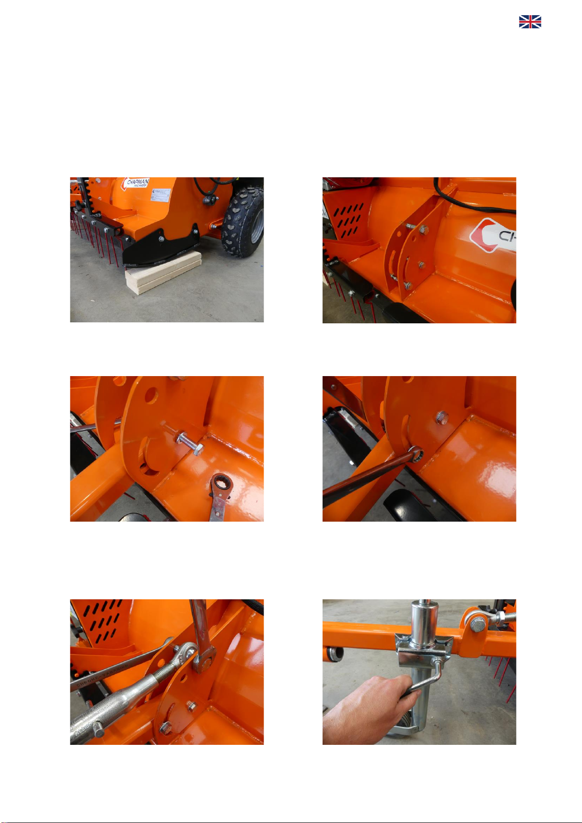
Initial Assembly of the Machine (if applicable)
If delivered from a local distributor, the PC Series should be fully assembled, PDI’d & ready to go. For some customers the PC120 is shipped direct
from the factory, with the machine standing vertically on the pallet for ease of transport. Please follow instructions below for initial assembly.
Drawbar
Tools required: 17, 19 & 24mm Spanners
1. Lower the Paddock cleaner gently down with
supports beneath the black skid plates.
2. Remove the three bolts from the drawbar mount
(shown below), taking note of the number and
location of washers so that they are fitted in the
correct number on re-assembly.
3. Next, install the REARMOST M12 bolt to the bottom
rear of the drawbar mount by offering up the
drawbar, inserting the bolt and fitting the washers
and nut loosely.
4. Next, install the FRONTMOST M12 bolt & nut in
the slot at the front of the drawbar mount, again
fitting washers and nuts loosely
5. Supporting the weight of the drawbar, lift up until the
drawbar adjuster is in-line with the last M16 bolt at the top of
the drawbar mount, installing washers and nuts loosely..
There should be one aluminium spacing bush either side of
the adjuster itself (not shown in picture).
6. Tighten the top M16 bolt and nut using 24mm spanners
such that it secures the assembly without distorting the
orange drawbar mount inwards. Likewise the 2 x M12 bolts
need to be tightened to a sliding fit using 19mm spanners
so that the drawbar mount is not distorted inwards and it
can move freely when the height adjuster is rotated
7. Lastly, install the Jockey wheel by unwinding the clamp, insert the jockey wheel into the clamp and tightening securely.

English
5
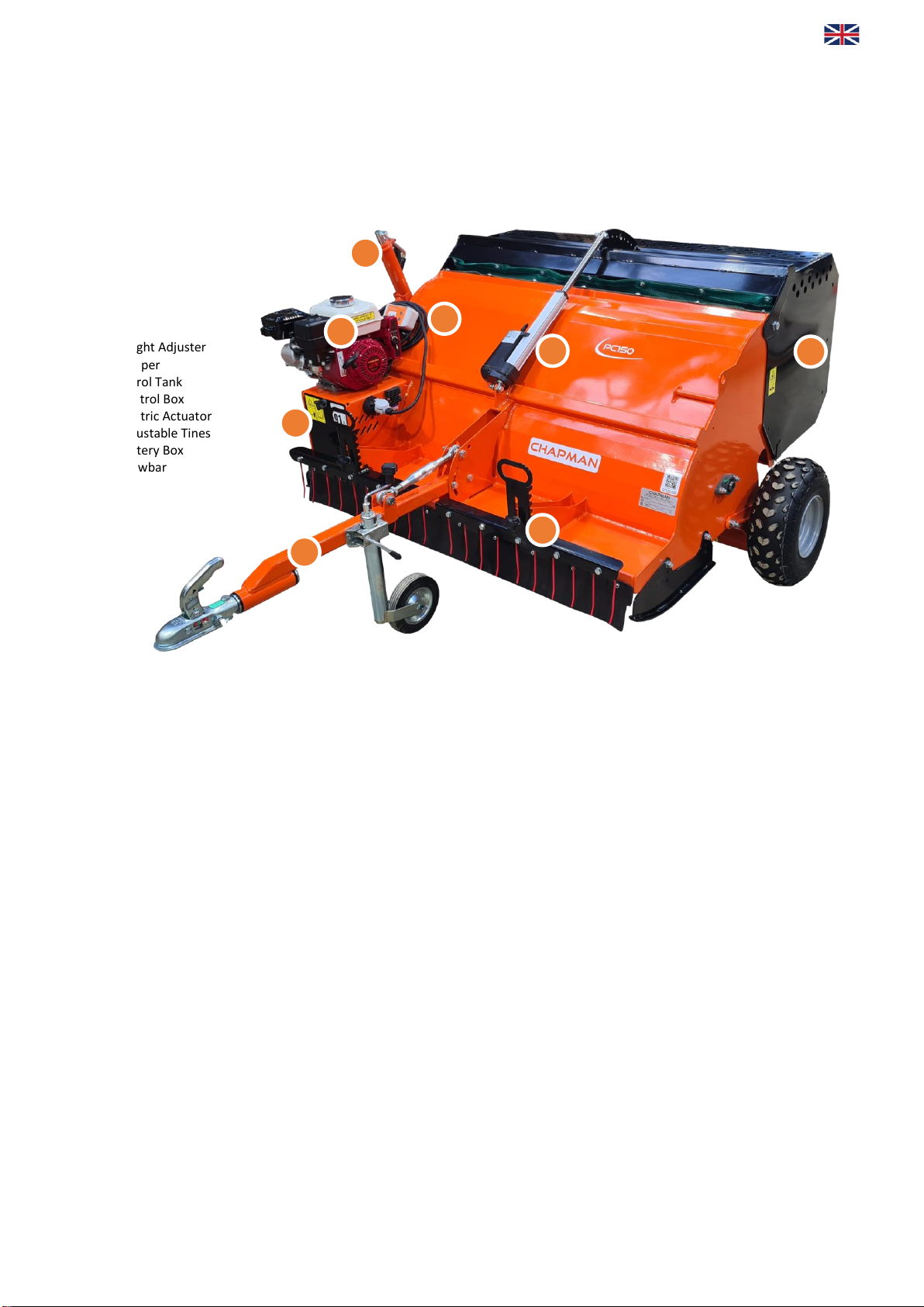
Component Identification / Labelling
For standard PC Series, the engine controls are all located on the engine, and detailed within the Honda engine manual.
For machines with the optional remote throttle fitted, all controls EXCEPT the throttle are as per the standard Honda engine. The throttle on the
remote throttle option machine can only be actuated from the remote throttle, and not on the engine itself.
1) Height Adjuster
2) Hopper
3) Petrol Tank
4) Control Box
5) Electric Actuator
6) Adjustable Tines
7) Battery Box
8) Drawbar
BELT
COVER
1
\
2
\
4
\
5
\
3
\
7
\
6
\
8
\

English
6
Attachment
Before Attaching the Machine
Before attachment, ALWAYS ensure the following:
•All safety guards & decals are in good working order and correctly fitted
•Lubrication points have been lubricated as per scheduled maintenance period
•The tyres are free of damage and inflated to the correct pressure
•Electrical connections are free of dirt and moisture
•The engine oil level is correct & has been maintained as per the handbook
•Drive belt(s) are in good working order
•The tyres are free of damage and inflated to the correct pressure (0.35-0.55 Bar [5-8psi])
Attaching the Machine
NOTE: This machine is designed to attach to the towing vehicle through a 50mm diameter ball hitch.
Reverse the towing vehicle up to the machine.
1. Reverse the towing vehicle up to the machine
2. Attach the machine onto the towing vehicle’s coupling using either the auto-lock coupling or suitable pin
hitch. Ensure the hitch is securely attached to the towing vehicle
3. If applicable, attach the remote throttle in a secure location within easy reach by the operator.
Initial Set-up
Height
1. Hitch the PC Series up to the towing vehicle, and drive into the field or yard to be swept.
2. Start the machine and increase the revs to full speed once warm. Lower the main height adjustment using the height adjuster handle
located near the engine until the sweeper brush is very lightly sweeping the surface. Running the brush too close to the ground will lead
to excessive scarifying of the field and excessive wear on the brushes.
3. Adjust the angle of the main deck using the top link adjuster on the top of the drawbar so that the machine sits level. Once this has
been adjusted to a desirable level the drawbar adjuster does not need to be altered unless a different towing vehicle is used, or the
brushes are becoming worn. In normal use it is only the main height adjuster that is used.
4. Adjust the height of the spring tines to the desired level of agitation and as the tines wear through normal use.
Daily Checks
Before use each day, and with the engine switched off and keys removed, the following checks should be undertaken;
•Brushes - With the engine switched off and keys removed, the condition of the brushes should be checked. Any damaged or missing
brushes should be replacedimmediately.
•Engine - Fluid levels should be checked daily before use and topped-up as necessary. Ensure the air intake and air filter are clear of
debris or excessive dust build-up. Ensure engine is in good order and maintained as per engine manufacturer schedule.
•Bearings - Ensure bearings are in good order and greased as per the maintenance schedule.
•Belts - Ensure belts are in good order, free of debris, dirt and grease and do not have signs of damage e.g. cracking, frayed edges,
uneven wear.
•Fuel - Ensure fuel is clean and free of dirt / debris. If necessary, check condition of fuel filter.
•Hitch - Check condition of swivel hitch, and ensure this is attached securely to towingvehicle.
•Tyres - Ensure tyres are free from damage and inflated to the correct working pressure for the conditions at hand
ENSURE CONTROL EQUIPMENT (IF APPLICABLE) IS SECURELY ATTACHED TO THE TOWING
VEHICLE BEFORE USE

English
7
Operation
Starting Work
After ensuring all daily checks have been undertaken, start the engine as per the manufacturer recommended procedure, utilising choke and
throttle as required. Once the engine is running and warm, engage drive by increasing the engine throttle to maximum. NOTE: The engine must
always be run at full speed, otherwise damage to the engine or gearbox can occur during use
Operating Limits
Minimum / Maximum Ambient Temperature -15°C / +40°C
Minimum / Maximum Altitude 0 meters / 1500 meters *
Maximum Inclination 20° in any direction
Maximum Speed 8km/h (5mph)
Forward Speed
The forward working speed will depend greatly on the working conditions and nature of the material being cut. Optimal speed will be in the
region of 3-8 km/h (2-5 mph).
Tipping Mechanism/Control Box
The PC Series comes with electric tipping. To operate the electric tip, this
is done via a simple two button control for open & close (see right) and
single push operation.
The control box also comes with two warning lamps;
Double Triangle: Overload Detection –this will light up something has
become trapped within the mechanism and will stop the open/shutting.
Battery: If the light is showing, this indicates an insufficient battery
voltage. Charge battery before attempting use again.
Storage
Machines should always be stored under cover and protected from the elements accordingly.
For extended periods of storage, it is advisable that the machine be first cleaned thoroughly and fully lubricated. Any servicing and maintenance
should be undertaken prior to storage, and any worn components replaced.
Machine Disposal
Disposal of this machine and any of its component parts must be performed in a responsible and inoffensive manner respecting all current laws
relating to this subject. Materials forming this machine that must undergo differentiated division and disposal are:
•Steel
•Mineral Oil
•Rubber
•Plastic
THE ENGINE MUST BE RUN AT MAXIMUM SPEED AT ALL TIMES WHEN IN USE!
Fuel should be treated with a suitable fuel stabilizer before extended storage.

English
8
Maintenance
All maintenance, cleaning and repair operations must be performed with the machine suitably supported, the engine switched off (and cool), and
the ignition keys removed.
Maintenance Schedule
After 1 hour of work
•Check all nuts and bolt for tightness –retighten if required.
•Check belt tension and taper lock tightness –adjust / tighten if required
•Grease main brush rotor bearing
Every 8 hours or daily
CHECK
•Check all nuts and bolt for tightness –retighten if required.
•Check condition in engine air filter –clean / replace as required
•Check wear and condition of brushes
•Check Oil level and top up if necessary
LUBRICATE
•Lubricate main rotor bearings –apply 20 shots of grease to each main rotor bearing
After every 100 hours (or annually, whichever occurs first), in addition to the above
CHECK
•Check belt condition - replace if required
•Check axle bearing condition - replace or lubricate as required
•Check main rotor bearings condition - replace as required
•Check condition of battery & connections
•Check condition of brushes and tines and replace as required
•Check condition of battery cables - replace if damaged
•Grease height adjustment mechanism –apply 20 shots of grease
Troubleshooting
Problem
Possible Causes
Remedies
FOR COMMERCIAL USE, LOG ENGINE HOURS AND RUN TIMES TO ENSURE
MAINTENANCE IS CARRIED OUT AS PER THE ENGINE MANUFACTURER SCHEDULE

English
9
Problem
Possible Causes
Remedies
Warranty
The Chapman Warranty
Chapman Machinery Ltd (herein ‘Chapman’ or ‘Chapman Machinery’) warrants that the machine referred to in the Warranty Registration Form
will be free from manufacturing defects for a period of 24 months from the date of sale. This warranty does not affect your statutory rights, but
merely adds to them. Should you have a problem within 24 months from the date of sale please contact your original dealer, or Chapman
Machinery’s Service Department.
Any part found to be defective during this period will be replaced or repaired, at our discretion, by the dealer or a authorised Service Engineer.
Warranty Conditions
1. The Warranty Registration Form must be completed and returned to Chapman Machinery Ltd within 30 days of the date of sale
2. This warranty does not cover defects arising from fair wear and tear, wilful damage, negligence, misuse, abnormal working conditions,
use in competition, failure to follow Chapman Machinery’s instructions (oral or written, including all instructions and recommendation
made in the Operator’s Manual) or alteration or repair of the machinery without prior approval.
3. The machinery must have been serviced in accordance with the Operator’s Manual and the Service Log must have been kept up to date
and made available to the dealer should service, repair or warranty work be undertaken.
4. This warranty does not cover claims in respect of wearing parts such as blades, flails, paintwork, tyres, belts, hydraulic hoses, bearings,
bushes, linkage pins, top links, ball ends unless there is a manufacturing or material defect or the cost of normal servicing items such as
oils and lubricants.
5. This warranty does not cover any expenses or losses incurred whilst the machinery is out of use for warranty repairs or parts
replacement.
6. This warranty does not extend to parts, materials or equipment not manufactured by Chapman Machinery, for which the Buyer shall
only be entitled to the benefit of any such warranty or guarantee given by themanufacturer to Chapman Machinery. Only genuine
replacement parts will be allowable for warranty claims.
7. All parts replaced by Chapman Machinery under warranty become the property of Chapman Machinery and must be returned to
Chapman Machinery if so requested. Such parts may only be disposed of after a warranty claim has been accepted and processed by
Chapman Machinery.
8. Chapman Machinery is not liable under this warranty for any repairs carried out without Chapman Machinery’s written consent or
without Chapman Machinery being afforded a reasonable opportunity toinspect the machinery the subject of the warranty claim.
Chapman Machinery’s written consent must, therefore, be obtained before any repairs are carried out or parts replaced. Use of non-
Chapman Machinery parts automatically invalidates the Chapman Warranty. Failed components must not be dismantled except as
specifically authorised by Chapman Machinery and dismantling of any components without authorisation from Chapman Machinery will
invalidate this warranty.
9. All warranty claims must be submitted to Chapman Machinery on Chapman Machinery Warranty Claim Forms within 30 days of

English
10
completion of warrantywork.
10. Using the machine implies the knowledge and acceptance of these instructions and the limitations contained in this Manual.
Transfer of Warranty
The Chapman warranty be transferred to a subsequent owner of the machinery (for use within the UK only) for the balance of the warranty
period subject to all of the stated warranty conditions and provided that the Change of Owner form is completed and sent to Chapman
Machinery within 14 days of change of owner- ship.
Chapman Machinery Ltd retain the right to refuse transfer of warranty.
Chapman Machinery reserves the right to make alterations and improvements to any machinery
without notification and without obligation to do so.

11
DECLARATION OF CONFORMITY
EU: Machinery Directive 2006/42/EC
UK: Supply of Machinery (Safety) Regulations 2008
Manufacturer: Chapman Machinery Ltd, Hele Barton, Week St Mary, Holsworthy, Devon, EX22 6XR, UK
Product(s) covered: PC120/150 Powered Collector
Serial Number: Stated on Accompanying Invoice
Standards and Regulations Used: Machinery Directive 2006/42/EC
Supply of Machinery (Safety) Regulations 2008
Place of Issue: United Kingdom
Name of Representative: James Chapman
Position of Representative: Director
Basis of Conformity Declaration: Self Declaration by Manufacturer
Declaration:
I declare that as the authorised representative, the above information in relation to the supply / manufacture of
this product, is in conformity with the stated standards and other related documents following the provisions of
Machinery Directive 2006/42/EC directives [EU] and Supply of Machinery (Safety) Regulations 2008 [UK]
The products described above comply with the essential requirements of the directives specified.
Signed:
Date: 06/04/2022

Deutsch
12
Einführung
DIESES HANDBUCH MUSS DEM BEDIENER VOR DER BENUTZUNG AUSGEHÄNDIGT WERDEN. DER BEDIENER MUSS DEN INHALT DIESES
HANDBUCHSVOLLSTÄNDIG VERSTEHEN , BEVOR ER DIE MASCHINE ZUM ERSTEN MAL BENUTZT. WENN DAS GERÄT WEITERVERKAUFT WIRD,
MUSS DIESES HANDBUCH DER MASCHINE BEILIEGEN .
HINWEIS: Die in diesem Handbuch enthaltenen Informationen sind zum Zeitpunkt der Drucklegung korrekt. Im Laufe der Entwicklung sind
jedoch Änderungen der Spezifikationen unvermeidlich. Sollten Sie feststellen, dass die angegebenen Informationen nicht mit Ihrer
Maschine übereinstimmen, wenden Sie sich bitte direkt an Chapman Machinery Ltd, um Rat zu erhalten. Verwenden Sie nur Chapman-
Originalersatzteile für Chapman-Maschinen und -Geräte.
Wichtige Sicherheitsinformationen
Lesen Sie dieses Handbuch immer, bevor Sie die Maschine montieren oder in Betrieb nehmen - wenden Sie sich im Zweifelsfall an Ihren
Händler oder die Kundendienstabteilung von Chapman Machinery, um Rat und Hilfe zu erhalten.
•Bedienen Sie dieses Gerät nur, wenn Sie dieses Handbuch vollständig gelesen haben.
•Verwenden Sie diese Maschine nur für die vorgesehene Aufgabe - unsachgemäßer Gebrauch ist sehr gefährlich und schadet den
Maschinenkomponenten.
•Sowohl Bediener als auch Wartungspersonal sollten mit der Maschine vertraut sein und sich der Gefahren bewusst sein, die mit
einer unsachgemäßen Verwendung oder falschen Reparaturen verbunden sind.
•Führen Sie vor dem Start eine Sichtprüfung der Maschine und des Zugfahrzeugs in Bezug auf Funktionalität, Verkehrssicherheit
und Unfallverhütungsvorschriften durch.
•Auch bei sachgemäßer Verwendung der Maschine können Unfälle passieren. Es ist unbedingt erforderlich, dass sich niemand im
Gefahrenbereich aufhält. Wenn Sie in der Nähe von Straßen, Gebäuden oder Tieren arbeiten, müssen Sie besonders vorsichtig
sein, um die Sicherheit zu gewährleisten.
•Tragen Sie niemals lose Kleidung, die sich in rotierenden Geräten verfangen könnte.
•Befördern Sie niemals Passagiere auf dem Zugfahrzeug
•Halten Sie sich während des Betriebs nicht in der Nähe der Maschine auf.
•Beschädigte oder fehlende Sicherheitsaufkleber müssen sofort ersetzt werden.
Sicherheit im Verkehr
•Verringern Sie beim Transport, insbesondere auf unebenem Gelände, die Geschwindigkeit, um Schäden an der Maschine zu
vermeiden.
•Sicherstellen, dass die Zündschlüssel abgezogen sind
•Diese Maschine ist nicht für den Straßenverkehr zugelassen. NICHT auf öffentlichen Straßen abschleppen
•Transportieren Sie die Maschine niemals mit laufendem Rotor, auch nicht über kurze Strecken.
Betriebssicherheit
•Sollten sich Drähte, Seile oder Ketten im Rotor verfangen, halten Sie sofort an, um Schäden oder gefährliche Situationen zu
vermeiden; halten Sie den Rotor und die Zugmaschine an, ziehen Sie den Startschlüssel oder die Sicherheitsabschaltung ab. Ziehen
Sie Arbeitshandschuhe an und befreien Sie den Rotor mit Hilfe einer Zange oder Schere. Versuchen Sie nicht, sich zu entwirren.
•Achten Sie bei der Arbeit mit der Maschine besonders darauf, dass Sie keine festen Gegenstände wie Straßenabläufe, Mauern,
Schächte, Bordsteine, Leitplanken, Schienen usw. berühren. Dies könnte die Bürsten oder das Gerät selbst beschädigen.
•Benutzen Sie die Maschine nicht, wenn übermäßige Vibrationen auftreten, da dies zu Brüchen und schweren Schäden führen kann
- finden Sie die Ursache der Vibrationen und beseitigen Sie sie, bevor Sie die Maschine wieder benutzen.

Deutsch
13
Beschreibung
Der Pferdeäpfelsammler der PC-Serie ist so konstruiert, dass er Pferdemist und andere Verunreinigungen mühelos aufnimmt, um die Pflege
von Pferdekoppeln schnell und einfach zu gestalten. Die PC-Serie ist mit einem einzigartigen elektrischen Kippmechanismus ausgestattet,
der eine einfache Entleerung des Auffangbehälters durch eine einfache Steuerung ermöglicht.
Der Pferdeäpfelsammler der PC-Serie ist ein gezogenes Anbaugerät, das in zwei Größen erhältlich ist: 1,2 m (PC120) und 1,5 m (PC150). 8
Polyethylenbürsten in 4 Reihen, angetrieben von einem Honda GX200 6,5 PS-Motor, sammeln den Mist in einen großen Auffangbehälter.
Der Motor ist mit einem einfachen Elektrostart und einem optionalen Ferngaszug ausgestattet, so dass der Gashebel bei Bedarf auf der
Rückseite eines Geländefahrzeugens angebracht werden kann.
Diese Maschinen sollten jedoch nur für die Aufgaben verwendet werden, für die sie konstruiert wurden - die Verwendung der Maschine für
andere Funktionen kann sowohl für Personen gefährlich sein als auch potenziell die Komponenten beschädigen. Die Verwendung des Geräts
über den angegebenen Verwendungszweck hinaus kann zum Erlöschen jeglicher Garantie führen und stellt möglicherweise einen Verstoß
gegen die geltenden Sicherheitsvorschriften dar.
Identifizierung
Jede Maschine ist mit einem Serienschild versehen (siehe unten), das
folgende Angaben enthält:
5. Modell
6. Datum der Herstellung
7. Seriennummer
8. Masse
Wenn Sie sich nach Ersatzteilen oder zusätzlicher Ausrüstung erkundigen,
stellen Sie sicher, dass Sie diese Informationen zur Hand haben.
Lärmpegel
Der Geräuschpegel dieser Maschine, gemessen am typischen Standort des Bedieners unter normalen Betriebsbedingungen, beträgt 91dB.
Beim Abschleppen durch ein Fahrzeug mit offener Fahrerkabine ist das Tragen eines Gehörschutzes oder eines geeigneten Helms
unerlässlich. Wenn das Fahrzeug hinter einem Nutzfahrzeug, 4x4 oder ähnlichem mit geschlossener Kabine gezogen wird, sollte die Kabine
geschlossen bleiben, um den Lärm zu reduzieren. Es liegt in der Verantwortung des Betreibers, dafür zu sorgen, dass der von ihm
empfundene Lärmpegel innerhalb der gesetzlichen Grenzen liegt.
Aufkleber am Gerät
Wenn Ihr Gerät nicht alle der unten aufgeführten Aufkleber enthält, wenden Sie
sich bitte vor dem Einsatz an Ihren Ausrüster, um Ersatzaufkleber zu erhalten.
Anmerkung: Alle Aufkleber müssen vorhanden und sichtbar sein. Diese müssen
unbedingt ersetzt werden, wenn sie beschädigt sind, um mögliche Schäden für die Benutzer zu vermeiden.
WARNUNG - Lesen Sie die
Bedienungsanleitung, bevor
Sie mit dieser Maschine
arbeiten. Beachten Sie beim
Betrieb die Vorschriften und
Sicherheitsregeln
VORSICHT - Gefahr des
Verhedderns. Halten Sie die
Hände von rotierenden
Bauteilen fern
VORSICHT - Rotierende
Messer. Halten Sie einen
angemessenen
Arbeitsabstand zur
Maschine ein und halten Sie
Hände und Füße von den
Messern fern.
VORSICHT -
Einklemmgefahr. Während
des Betriebs die Hände von
der Maschine fernhalten
BEI DER BEDIENUNG DIESES GERÄTS MÜSSEN STETS GEHÖRSCHÜTZER ODER
GLEICHWERTIGE GEHÖRSCHUTZMITTEL GETRAGEN WERDEN!

Deutsch
14
Erstmontage der Maschine (falls zutreffend)
Wenn die PC-Serie von einem lokalen Händler geliefert wird, sollte sie vollständig montiert, geprüft und einsatzbereit sein. Für einige Kunden wird
die PC120 direkt ab Werk geliefert, wobei die Maschine zum leichteren Transport senkrecht auf der Palette steht. Bitte folgen Sie den
nachstehenden Anweisungen für die Erstmontage.
Deichsel
Erforderliche Werkzeuge: 17, 19 & 24mm Schraubenschlüssel
5. Senken Sie den Pferdeäpfelsammler vorsichtig ab und
stützen Sie ihn unter den schwarzen Kufenplatten ab.
6. Entfernen Sie die drei Schrauben von der Deichselhalterung (siehe unten)
und notieren Sie sich die Anzahl und Position der Unterlegscheiben,
damit sie beim Wiedereinbau in derrichtigen Anzahl angebracht werden.
7. Montieren Sie als Nächstes die REARMOST M12-Schraube
an der unteren Rückseite der Deichselhalterung, indem Sie
die Deichsel nachoben führen, die Schraube einführen und
die Unterlegscheiben und die Mutter locker anbringen.
8. Montieren Sie als nächstes die VORDERSTE M12-Schraube und -Mutter in
den Schlitz an der Vorderseite der Deichselhalterung, wobei Sie
wiederum Unterlegscheiben und Muttern locker anbringen.
9. Stützen Sie das Gewicht der Deichsel und heben Sie sie an,
bis der Deichselversteller mit der letzten M16-Schraube
oben an der Deichselhalterung ausgerichtet ist. Auf beiden
Seiten des Verstellers sollte sich eine Aluminium-
Distanzbuchse befinden (nicht im Bild).
10. Ziehen Sie die obere M16-Schraube und Mutter mit einem 24-mm-
Schraubenschlüssel so an, dass dieBaugruppe gesichert ist, ohne die
orangefarbene Deichselhalterungnach innen zu verformen. Ebenso müssen
die2 x M12-Schrauben mit einem 19-mm-Schlüssel gleitend angezogen
werden, damit die Deichselhalterung nicht nach innen verzogen wird und
sich beim Drehender Höhenverstellung frei bewegenkann
7. Zum Schluss montieren Sie das Stützrad, indem Sie die Klemme lösen, das Handhabungsrad in die Klemme einsetzen undfest anziehen.

Deutsch
15
Identifizierung / Kennzeichnung von Bauteilen
Bei der Standard-PC-Serie befinden sich alle Motorsteuerungen am Motor und sind im Honda-Motorhandbuch beschrieben.
Bei Maschinen mit optionalem Ferngashebel entsprechen alle Bedienelemente mit Ausnahme des Gashebels denen des Standard-Honda-
Motors. Die Drosselklappe der Maschine mit Ferndrosseloption kann nur von der Ferndrosselklappe aus betätigt werden, nicht aber am
Motor selbst.
9) Höhenverstellung
10) Auffangbehälter
11) Benzintank
12) Schaltkasten
13) Elektrischer Aktuator
14) Einstellbare Zinken
15) Akku-Box
16) Deichsel
RIEMENA
BDECKUN
G
1
\
2
\
4
\
5
\
3
\
7
\
6
\
8
\

Deutsch
16
Anbau
Vor dem Anbringen der Maschine
Stellen Sie vor der Befestigung IMMER Folgendes sicher:
•Alle Schutzvorrichtungen und Aufkleber sind in einwandfreiem Zustand und korrekt angebracht
•Die Schmierstellen wurden gemäß den geplanten Wartungsintervallen geschmiert.
•Die Reifen sind nicht beschädigt und haben den richtigen Luftdruck
•Elektrische Anschlüsse sind frei von Schmutz und Feuchtigkeit
•Der Motorölstand ist korrekt und wurde gemäß dem Handbuch gewartet.
•Der/die Antriebsriemen sind in gutem Zustand
•Die Reifen sind nicht beschädigt und haben den richtigen Luftdruck (0,35-0,55 Bar [5-8psi])
Anbringen der Maschine
HINWEIS: Diese Maschine ist so konzipiert, dass sie über eine Kugelkupplung mit 50 mm Durchmesser am Zugfahrzeug befestigt werden kann.
Fahren Sie das Zugfahrzeug rückwärts an die Maschine heran.
4. Das Zugfahrzeug rückwärts an die Maschine heranfahren
5. Befestigen Sie die Maschine an der Kupplung des Zugfahrzeugs mit Hilfe der selbstsichernden Kupplung oder eines geeigneten
Bolzens. Anhängevorrichtung. Vergewissern Sie sich, dass die Anhängerkupplung sicher am Zugfahrzeug befestigt ist.
6. Bringen Sie den Ferngashebel gegebenenfalls an einem sicheren Ort an, der für den Bediener leicht erreichbar ist.
Erstmalige Einrichtung
Höhe
5. Kuppeln Sie die PC-Serie an das Zugfahrzeug an und fahren Sie auf das zu kehrende Feld oder den Hof.
6. Starten Sie die Maschine und erhöhen Sie die Drehzahl auf volle Geschwindigkeit, sobald sie warm ist. Senken Sie die
Haupthöheneinstellung mit dem Höheneinstellgriff in der Nähe des Motors ab, bis die Kehrbürste die Oberfläche nur noch ganz
leicht abstreift. Wenn die Bürste zu nahe am Boden geführt wird, führt dies zu einer übermäßigen Vertikutierung des Feldes und
einem übermäßigen Verschleiß der Bürsten.
7. Stellen Sie den Winkel des Hauptdecks mit dem Oberlenker-Einsteller oben an der Deichsel so ein, dass die Maschine waagerecht
steht. Ist diese auf ein gewünschtes Niveau eingestellt, muss die Deichselnachstellung nicht mehr verändert werden, es sei denn,
es wird ein anderes Zugfahrzeug verwendet oder die Bürsten sind abgenutzt. Im normalen Gebrauch wird nur die
Haupthöhenverstellung verwendet.
8. Stellen Sie die Höhe der Federzinken auf den gewünschten Rührgrad ein.
Tägliche Checks
Vor der täglichen Benutzung, bei abgestelltem Motor und abgezogenem Schlüssel, sollten folgende Kontrollen durchgeführt werden;
•Bürsten - Bei abgestelltem Motor und abgezogenen Schlüsseln sollte der Zustand der Bürsten überprüft werden. Beschädigte
oder fehlende Bürsten sollten sofort ersetzt werden.
•Motor - Der Flüssigkeitsstand sollte täglich vor der Benutzung überprüft und bei Bedarf aufgefüllt werden. Vergewissern Sie sich,
dass der Lufteinlass und der Luftfilter frei von Verschmutzungen oder übermäßiger Staubansammlung sind. Vergewissern Sie sich,
dass der Motor in gutem Zustand ist und gemäß den Vorgaben des Motorherstellers gewartet wird.
•Lager - Stellen Sie sicher, dass die Lager in gutem Zustand sind und gemäß dem Wartungsplan geschmiert werden.
•Riemen - Vergewissern Sie sich, dass die Riemen in gutem Zustand, frei von Ablagerungen, Schmutz und Fett sind und keine
Anzeichen von Beschädigungen aufweisen, z. B. Risse, ausgefranste Kanten, ungleichmäßige Abnutzung.
•Kraftstoff - Stellen Sie sicher, dass der Kraftstoff sauber und frei von Schmutz und Ablagerungen ist. Gegebenenfalls den Zustand
des Kraftstofffilters überprüfen.
•Anhängevorrichtung - Überprüfen Sie den Zustand der Anhängevorrichtung und stellen Sie sicher, dass diese sicher am
Zugfahrzeug befestigt ist.
•Reifen - Vergewissern Sie sich, dass die Reifen nicht beschädigt sind und den richtigen Luftdruck für die jeweiligen Bedingungen haben.
STELLEN SIE SICHER, DASS DIE STEUERGERÄTE VOR DER VERWENDUNG SICHER AM
ZUGFAHRZEUG BEFESTIGT SIND

Deutsch
17
Bedienung
Beginn der Arbeit
Nachdem Sie sich vergewissert haben, dass alle täglichen Kontrollen durchgeführt wurden, starten Sie den Motor gemäß der vom
Hersteller empfohlenen Vorgehensweise, wobei Sie bei Bedarf den Choke und das Gaspedal betätigen. Sobald der Motor läuft und warm
ist, schalten Sie den Antrieb ein, indem Sie die Drosselklappe auf Maximum stellen. HINWEIS: Der Motor muss immer mit voller Drehzahl
betrieben werden, da sonst Motor- oder Getriebeschäden während des Betriebs auftreten können.
Betriebsgrenzwerte
Minimale / maximale Umgebungstemperatur -15°C / +40°C
Minimale / maximale Flughöhe 0 Meter / 1500 Meter *
Maximale Neigung 20° in jede Richtung
Maximale Geschwindigkeit 8km/h (5mph)
Vorwärtsgeschwindigkeit
Die Arbeitsgeschwindigkeit hängt stark von den Arbeitsbedingungen und der Art des zu schneidenden Materials ab. Die optimale
Geschwindigkeit liegt im Bereich von 3-8 km/h (2-5 mph).
Kippmechanismus/Schaltkasten
Die PC-Serie ist mit elektrischer Kippvorrichtung ausgestattet. Die Bedienung der
erfolgt über eine einfache Zwei-Knopf-Bedienung zum Öffnen und Schließen (siehe
rechts) und eine einfache Druckbetätigung.
Der Schaltkasten ist außerdem mit zwei Warnlampen ausgestattet;
Doppeltes Dreieck: Überlastungserkennung - leuchtet auf, wenn sich etwas im
Mechanismus verklemmt hat, und stoppt das Öffnen/Schließen.
Batterie: Wenn das Lämpchen leuchtet, weist dies auf eine unzureichende
Batteriespannung hin. Laden Sie den Akku auf, bevor Sie ihn wieder verwenden.
Lagerung
Bei längerer Lagerung ist es ratsam, die Maschine zunächst gründlich zu reinigen und vollständig zu schmieren. Alle Wartungs- und
Instandhaltungsarbeiten sollten vor der Einlagerung durchgeführt und verschlissene Teile ersetzt werden.
Maschinenentsorgung
Die Entsorgung dieser Maschine und ihrer Bestandteile muss auf verantwortungsvolle und unschädliche Weise und unter Beachtung aller
geltenden Gesetze zu diesem Thema erfolgen. Die Materialien, die diese Maschine bilden und die differenziert getrennt und entsorgt
werden müssen, sind:
•Stahl
•Mineralöl
•Gummi
•Kunststoff
DER MOTOR MUSS WÄHREND DES BETRIEBS IMMER MIT MAXIMALER DREHZAHL LAUFEN!
Kraftstoff sollte vor einer längeren Lagerung mit einem geeigneten
Kraftstoffstabilisator behandelt werden.

Deutsch
18
Wartung
Bei allen Wartungs-, Reinigungs- und Reparaturarbeiten muss die Maschine in geeigneter Weise abgestützt, der Motor abgestellt (und
abgekühlt) und der Zündschlüssel abgezogen werden.
Zeitplan für die Wartung
Nach 1 Stunde Arbeit
•Prüfen Sie alle Muttern und Schrauben auf festen Sitz - ziehen Sie sie bei Bedarf nach.
•Prüfen Sie die Riemenspannung und die Festigkeit der Kegelverriegelung - stellen Sie sie bei Bedarf ein bzw. ziehen Sie sie nach
•Lager des Hauptbürstenrotors einfetten
Alle 8 Stunden oder täglich
PRÜFUNG
•Prüfen Sie alle Muttern und Schrauben auf festen Sitz - ziehen Sie sie bei Bedarf nach.
•Zustand des Motorluftfilters prüfen - bei Bedarf reinigen/ersetzen
•Verschleiß und Zustand der Bürsten prüfen
•Ölstand prüfen und ggf. nachfüllen
SCHMIEREN
•Schmieren Sie die Hauptrotorlager - tragen Sie 20 Schuss Fett auf jedes Hauptrotorlager auf.
Nach jeweils 100 Betriebsstunden (oder jährlich, je nachdem, was zuerst eintritt), zusätzlich zu den
oben genannten
PRÜFUNG
•Zustand des Riemens prüfen - bei Bedarf austauschen
•Zustand der Achslager prüfen - bei Bedarf austauschen oder schmieren
•Zustand der Hauptrotorlager prüfen - bei Bedarf austauschen
•Zustand der Batterie und der Anschlüsse prüfen
•Zustand der Bürsten und Zinken prüfen und bei Bedarf ersetzen
•Zustand der Batteriekabel prüfen - bei Beschädigung ersetzen
•Mechanismus zur Höhenverstellung abschmieren - 20 Schuss Fett auftragen
Fehlersuche
Problem
Mögliche Ursachen
Abhilfemaßnahmen
BEI GEWERBLICHER NUTZUNG SIND DIE MOTORBETRIEBSSTUNDEN UND -
LAUFZEITEN ZU PROTOKOLLIEREN, UM SICHERZUSTELLEN, DASS DIE WARTUNG
GEMÄSS DEM ZEITPLAN DES MOTORHERSTELLERS DURCHGEFÜHRT WIRD.

Deutsch
19
Problem
Mögliche Ursachen
Abhilfemaßnahmen
Garantie
Die Chapman-Garantie
Chapman Machinery Ltd (im Folgenden "Chapman" oder "Chapman Machinery") garantiert, dass die im Garantie-Registrierungsformular
angegebene Maschine für einen Zeitraum von 24 Monaten ab dem Verkaufsdatum frei von Herstellungsfehlern ist. Diese Garantie schränkt
Ihre gesetzlichen Rechte nicht ein, sondern ergänzt sie lediglich. Sollten Sie innerhalb von 24 Monaten nach dem Verkaufsdatum ein
Problem haben, wenden Sie sich bitte an Ihren Händler oder an die Kundendienstabteilung von Chapman Machinery.
Jedes Teil, das sich während dieses Zeitraums als defekt erweist, wird nach unserem Ermessen durch den Händler oder einen autorisierten
Servicetechniker ersetzt oder repariert.
Garantiebedingungen
11. Das Garantie-Registrierungsformular muss ausgefüllt und innerhalb von 30 Tagen nach dem Verkaufsdatum an Chapman
Machinery Ltd zurückgeschickt werden.
12. Diese Garantie deckt keine Mängel ab, die durch normalen Verschleiß , vorsätzliche Beschädigung, Fahrlässigkeit, Missbrauch,
anormale Arbeitsbedingungen, Verwendung im Wettbewerb, Nichtbeachtung der Anweisungen von Chapman Machinery
(mündlich oder schriftlich, einschließlich aller Anweisungen und Empfehlungen in der Betriebsanleitung) oder Änderungen oder
Reparaturen an der Maschine ohne vorherige Genehmigung entstehen.
13. Die Maschine muss gemäß der Betriebsanleitung gewartet worden sein, und das Wartungsbuch muss auf dem neuesten Stand
gehalten und dem Händler im Falle von Wartungs-, Reparatur- oder Garantiearbeiten zur Verfügung gestellt worden sein.
14. Diese Garantie deckt keine Ansprüche in Bezug auf Verschleißteile wie Messer, Schlegel, Lackierung, Reifen, Riemen,
Hydraulikschläuche, Lager, Buchsen, Gestängebolzen, Oberlenker, Kugelköpfe ab, es sei denn, es liegt ein Fabrikations- oder
Materialfehler vor oder die Kosten für normale Wartungsarbeiten wie Öle und Schmiermittel.
15. Diese Garantie deckt keine Kosten oder Verluste ab, die entstehen, während die Maschine für Garantiereparaturen oder den
Austausch von Teilen außer Betrieb ist.
16. Diese Garantie erstreckt sich nicht auf Teile, Materialien oder Ausrüstungen, die nicht von Chapman Machinery hergestellt
wurden, für die der Käufer nur Anspruch auf die vom Hersteller an Chapman Machinery gewährte Garantie oder Gewährleistung
hat . Nur Originalersatzteile sind für Garantieansprüche zulässig.
17. Alle von Chapman Machinery im Rahmen der Garantie ersetzten Teile gehen in das Eigentum von Chapman Machinery über und

Deutsch
20
müssen auf Verlangen an Chapman Machinery zurückgegeben werden. Solche Teile dürfen erst dann entsorgt werden, wenn ein
Garantieanspruch von Chapman Machinery akzeptiert und bearbeitet wurde.
18. Chapman Machinery haftet im Rahmen dieser Garantie nicht für Reparaturen, die ohne die schriftliche Zustimmung von
Chapman Machinery oder ohne dass Chapman Machinery eine angemessene Gelegenheit zur Inspektion der Maschine, die
Gegenstand des Garantieanspruchs ist, erhalten hat, durchgeführt werden. Daher muss vor der Durchführung von Reparaturen
oder dem Austausch von Teilen die schriftliche Zustimmung von Chapman Machinery eingeholt werden. Die Verwendung von
Teilen, die nicht von Chapman Machinery stammen, führt automatisch zum Erlöschen der Chapman-Garantie. Defekte Bauteile
dürfen nur mit ausdrücklicher Genehmigung von Chapman Machinery demontiert werden, und die Demontage von Bauteilen
ohne Genehmigung von Chapman Machinery führt zum Erlöschen dieser Garantie.
19. Alle Garantieansprüche müssen innerhalb von 30 Tagen nach Beendigung der Garantiearbeiten mit dem Garantieantragsformular
von Chapman Machinery bei Chapman Machinery eingereicht werden.
20. Die Benutzung der Maschine setzt die Kenntnis und Akzeptanz dieser Anweisungen und der in diesem Handbuch enthaltenen
Einschränkungen voraus.
Übertragung der Garantie
Die Chapman-Garantie kann auf einen nachfolgenden Besitzer der Maschine (nur für die Verwendung innerhalb Großbritanniens) für die
restliche Garantiezeit übertragen werden, vorbehaltlich aller angegebenen Garantiebedingungen und unter der Voraussetzung, dass das
Formular für den Besitzerwechsel ausgefüllt und innerhalb von 14 Tagen nach dem Besitzerwechsel an Chapman Machinery geschickt wird.
Chapman Machinery Ltd behält sich das Recht vor, die Übertragung der Garantie abzulehnen.
Chapman Machinery behält sich das Recht vor, ohne Vorankündigung und ohne dazu verpflichtet zu sein, Änderungen und
Verbesserungen an allen Maschinen vorzunehmen.
This manual suits for next models
2
Table of contents
Languages:
Other Chapman Ultrasonic Jewelry Cleaner manuals