Chapman PC120 User manual


Page 2
Contents
HSE Information...............................................................................................................................................3
Important Safety Information..........................................................................................................................4
DEFINITIONS.................................................................................................................................................4
Safety Information .......................................................................................................................................4
Transportation Safety ..................................................................................................................................4
Operating Safety ..........................................................................................................................................4
Description.......................................................................................................................................................5
Identification................................................................................................................................................5
Noise Levels .................................................................................................................................................5
Component Identification............................................................................................................................9
Identification..............................................................................................................................................10
Implement Decals ......................................................................................................................................10
Attachment ....................................................................................................................................................11
Before Attaching the Machine...................................................................................................................11
Attaching the Machine...............................................................................................................................11
Initial Set-up...................................................................................................................................................12
Fuel Tank & Gearbox..................................................................................................................................12
Height.........................................................................................................................................................12
Daily Checks ...............................................................................................................................................12
Operation .......................................................................................................................................................13
Storage .......................................................................................................................................................13
Maintenance ..................................................................................................................................................14
Warranty ........................................................................................................................................................15
EC DECLARATION OF CONFORMITY...............................................................................................................16
THIS MANUAL MUST BE HANDED TO THE OPERATOR BEFORE USE. THE OPERATOR MUST UNDERSTAND FULLY
THE CONTENT OF THIS HANDBOOK BEFORE USING THE MACHINE FOR THE FIRST TIME. OF THE IMPLEMENT IS
RESOLD, THIS MANUAL MUST ACCOMPANY THE MACHINE.
NOTE:
The information contained in this manual is correct at the time of going to press. However, in the course of
development, changes in specification are inevitable. Should you find the information given differs from your
machine, please contact Chapman Machinery Ltd direct for advice. Use only Chapman Genuine Service Parts on
Chapman Machinery and Machines.

Page 3
HSE Information
Safe use of all-terrain vehicles (ATVs) in agriculture and forestry –AIS Sheet 33
Introduction
This information sheet gives advice on the safe use of ATVs. It
covers the two main types used in off-road working in agriculture
and forestry, which are:
•sit-astride ATV / sit-in machines
•side-by-side mini-utility vehicles,
The Full HSE information sheet can be found here or using the QR
Code at the bottom of the article:
https://www.hse.gov.uk/pubns/ais33.pdf and must be read prior to
any ATV/UTV use. Below are related extracts to trailed machinery.
REMEMBER - GET PROPERLY TRAINED AND ALWAYS
WEAR HEAD PROTECTION
Training
Under the Provision and Use of Work Equipment Regulations 1998
(PUWER), there is a legal requirement for employers to provide
adequate training, and to ensure that only employees who have
received appropriate training in their safe use, including the use of
any towed equipment or attachments, are permitted to ride ATVs.
The same requirements apply to the self- employed. HSE regards
training provided by recognised training providers as being
adequate for the purposes of PUWER.
Protective clothing
More than half of all ATV riders have been thrown off at some
time. As these machines are not fitted with either a cab or roll bar,
your only protection is what you wear.
●
Head protection is vital. The majority of ATV fatalities in the
UK in the last ten years have been caused by head injuries.
Nobody who died from head injuries was wearing a helmet.
Helmets would certainly have prevented most, if not all, the
deaths. You should always wear a helmet when riding an
ATV. All helmets should have a chinstrap and be capable of
being used with suitable eye protection. The type of helmet
chosen should be based on an assessment of the
circumstances in which the ATV will be used, eg the types of
surface travelled over and anticipated speeds. The harder
the surface and higher the speed the greater the degree of
protection needed. NB: Forestry helmets and industrial
hard hats are not acceptable for any ATV operations.
●
Wear clothing that is strong and covers your arms and legs.
Gloves are useful for protection and to keep hands warm in
cold weather for good control of the ATV. Wear sturdy,
ankle-covering footwear, eg boots or wellingtons that are
strong, supportive and have good wet grip.
●
Protect your eyes from insects and branches with either a
visor or goggles.
Trailed equipment and loads
Ensure all riders know the manufacturers recommended
towing capacity and drawbar loading limit. Always operate
within these requirements.
Remember that your ability to control the ATV by your body
movements will be considerably reduced when carrying a load or
towing a trailer.
●
When selecting trailed equipment look for:
-
over-run brakes;
-
a swivel hitch drawbar;
-
bead lock rims on wheels;
-
a low centre of gravity and a wide wheel track;
-
a long drawbar; and
-
attachment points for securing a load.
●
Check the weight ratio between your ATV and its trailed load.
This needs to be assessed for each operation. As a general
guide, on level ground, braked trailed equipment can be a
maximum of four times the unladen weight of the ATV. For
unbraked trailed equipment the maximum should be twice
the unladen weight. These loads should be reduced when
working on slopes, uneven ground or poor surface
conditions. Follow the manufacturers advice for your
particular machine.
●
Weight transfer is also important. Stability and resistance to
jack-knifing is improved if some load is transferred onto the
ATVʼs drawbar. Approximately 10% of the gross weight of the
loaded trailer is recommended, but this should not exceed
the manufacturers drawbar loading limit. Remember that
weight transfer can change dramatically when you start
going up or down hill.
●
When selecting mounted equipment, make sure it is within
the manufacturers approved weight limit, with a low centre
of gravity, and controls which are easy to operate but do not
create a hazard. Where equipment is added to one end of the
machine, add ballast at the other end to maintain stability.
●
Loads carried on racks must be well secured, e.g. with
ratchet straps, and be evenly balanced between the front
and rear, except where they are deliberately altered to aid
stability when going up or down a slope.
●
Only tow a load from the hitch point. Loads towed from other
points such as the rear rack have caused sudden rear
overturning even on slight slopes or with slight acceleration.
Ropes or chains should not be used to drag a load where they
can become caught on a wheel. This may lead to
entanglement with the brake cable, causing unexpected
braking.
Further information
For information about health and safety go to
https://www.hse.gov.uk/
© Crown copyright This publication
may be freely reproduced, except for
advertising, endorsement or
commercial purposes. First published
05/99. Please acknowledge the source
as HSE.

Page 4
Important Safety Information
Always read this manual before fitting or operating the machine –whenever any doubt exists contact your
dealer or the Chapman Machinery Service Department for advice and assistance.
DEFINITIONS
The following definitions apply throughout this manual:
WARNING - An operating procedure, technique etc., which can result in personal injury or loss of life if not
observed carefully.
CAUTION - An operating procedure, technique etc., which can result in damage to either machine or equipment if
not observed carefully.
NOTE - An operating procedure, technique etc, which is considered essential to emphasis.
LEFT & RIGHT HAND - This term is applicable to the machine when attached to the towing vehicle and is viewed
from the rear –this also applies to tractor references.
Safety Information
•Do not operate this equipment unless you have studied this manual in full
•Only use this machine for its designated task - improper use is both highly dangerous and damaging to
machine components
•Both operators & maintenance fitters should be familiar with the machine and fully aware of dangers
surrounding improper use or incorrect repairs
•Before starting, carry out a visual check on both machine & towing vehicle as regards functionality,road
safety & accident prevention rules
•Even when using the machine correctly, accidents can occur. It is imperative that nobody stand within the
danger area. If working near roads, buildings or animals, special attention must be taken to ensure safety.
•Never wear loose clothing which could get caught in rotating equipment
•Never carry passengers on the towing vehicle
•Do not stand near the machine when operating
•Damaged or missing safety decals must be replaced immediately
Transportation Safety
•When transporting, especially over rough ground, reduce speed to prevent damage to machine.
•This machine is not road legal in its standard form. DO NOT tow on public highways.
Operating Safety
•Pay special attention when working not to harm livestock if crowding around the machine occurs.
•If anything should become entangled in the mechanism, stop the machine and disconnect the power before
attempting to clear the blockage.

Page 5
Description
The PC120 Paddock Cleaner is designed to pick up horse dung and other debris with ease to make paddock
maintenance quick and easy.
The PC120 Paddock Cleaner is a trailed attachment, with 4 Polyethylene brushes powered by a Honda GX200 6.5hp
Engine collecting dung into a 550 (approx.) litre hopper. The engine comes with easy electric start and optional
remote throttle cable, allowing the installation of the throttle on the back of a Quad should it be required.
The PC120 also comes with a unique remote electric tipping mechanism that allows for easy emptying of the
hopper by a simple controller.
These machines should however only be used to perform tasks for which they were designed - use of the machine
for any other function may be both dangerous to persons, and potentially damaging to components. Use of the
machine beyond the stated usage may invalidate any applicable warranty, as well as being potential in breach of
applicable safety regulations.
Identification
Each machine is fitted with a serial plate (shown below) which details the following:
1. Model
2. Date of Manufacture (DOM)
3. Serial Number
4. Mass
When enquiring regarding spares or additional
equipment, ensure you have this information to hand.
Noise Levels
The sound of this machine, as measured at the typical operator location under normal operating conditions, is 91db.
If being towed by an open-cab vehicle, it is essential that ear defenders or a suitable helmet is worn at all times. If
being towed behind a closed-cab UTV, 4x4 or similar, then the cab should remain closed to reduce noise.
Ear defenders or other suitable protection should be worn at all times when
operating

Page 6
Assembly of Machine
The PC120 Paddock Cleaner is delivered vertical on a pallet for ease of transport. The PC120 needs some minor
assembly prior to use. Please see instructions below on assembling the PC120 from dispatch:
Tools needed: 17, 19 & 24mm Spanners
Lower the PC120 gently down with supports beneath the black skid plates.
Next, the drawbar needs to be attached. Remove the three bolt’s from the drawbar mount (see below) NOTE:
Don’t tighten the bolts until all are installed.

Page 7
Firstly, install the 19mm bolt to the bottom rear of the mount, offer the drawbar up and fit the bolt, washers and
nut loosely.
Next, install the other 19mm bolt & nut in through the most forward hole and again, loosely.
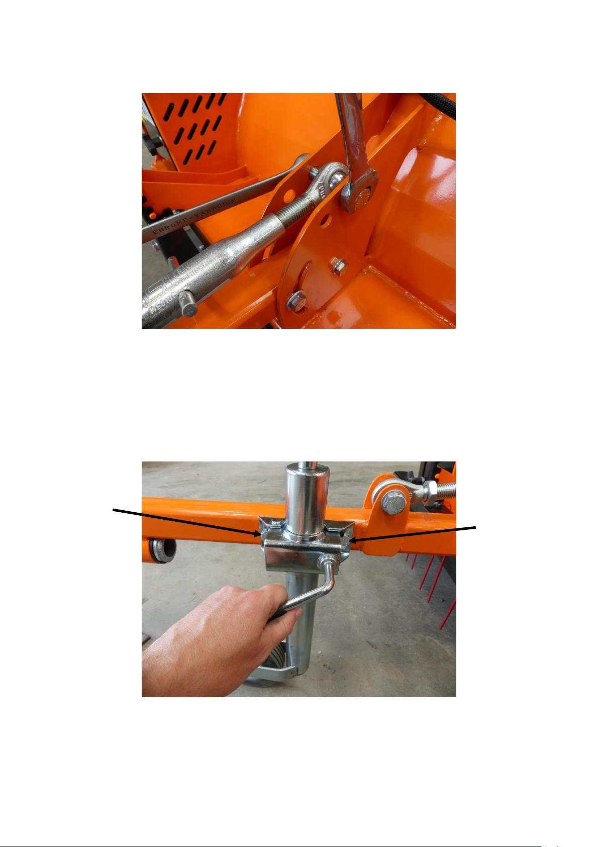
Supporting the weight of the drawbar, lift up until the drawbar adjuster is inline with the last 24mm bolt fitment at
the back of the drawbar mount & install. There should be one aluminium spacing bush on each side of the adjuster
assembly (not shown in picture).
Page 8
Do not overtighten the bolts, they only need to be just ‘nipped’ up to allow the drawbar to move up and down
when the adjuster is used.
Next, install the Jockey wheelby unwinding the jockey clamp, install the jockey wheel assembly into the clamp and
tightening securely.
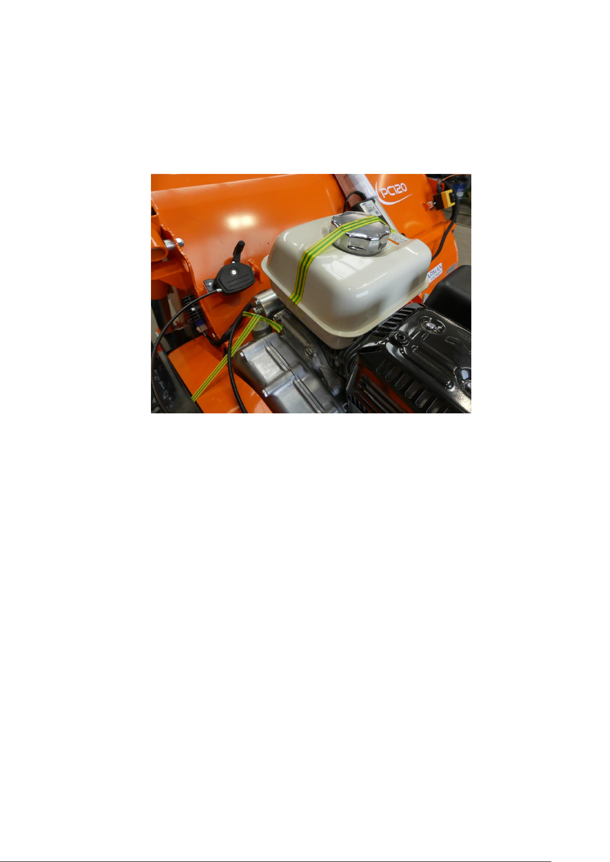
Finally, if not already done, remove all transport tape, typically yellow/green marked, which is used to
secure the fuel cap and breather cap on the gearbox.
operating

Page 9
Component Identification

Page 10
Identification
Each machine is fitted with a serial plate (shown below) which details the following:
1. Model
2. Date of Manufacture (DOM)
3. Serial Number
4. Mass
When enquiring regarding spares or additional
equipment, ensure you have this information to hand.
Implement Decals
If your implement does not contain all of the decals shown below, please contact your equipment supplier for
replacement decals before use.
Note: All decals must be present and visible. It is imperative that these are replaced if damaged to prevent potential
harm to users.
Carefully read operators
manual before handling
this machine. Observe in
structions and safety rules
when operating
Caution - Entanglement
Hazard. Keep hands away
from rotating
components
Caution - Rotating blades.
Maintain sensible working
distance from machine
and keep hands and feet
clear of blades
Caution - risk of trapping.
Keep hands away from
machine when in
operation

Page 11
Attachment
Before Attaching the Machine
Before attachment, ALWAYS ensure the following:
- All safety guards & decals are in good working order and correctly fitted
- Lubrication points have been lubricated as per scheduled maintenance period
- The tyres are free of damage and inflated to the correct pressure
- Electrical connections are free of dirt and moisture
-The engine oil level is correct & has been maintained as per the handbook
-Drive belt(s) are in good working order
Attaching the Machine
NOTE: This machine is designed to attach to the towing vehicle through a 50mm diameter ball hitch.
1. Reverse the towing vehicle up to the machine.
2. Attach the machine onto the towing vehicle’s coupling.
3. Attach the control cable to the control socket fitted on the towing machine, ensuring a secure connection.
NOTE: PC120 Models are fitted with a combined throttle / choke / stop cable. This provides the
emergency stop function should it be required. (Remote throttle for quad use)
ENSURE CONTROL EQUIPMENT IS SECURELY ATTACHED TO THE TOWING VEHICLE BEFORE USE
Page 12
Initial Set-up
Fuel Tank & Gearbox
The PC120 comes with engine & gearbox oil topped up. Prior to use, make sure you remove the protective tape on
top of the fuel tank, and breather pipe. (see below)
Height
Hitch the PC120 up to the towing vehicle, adjust the height of the roller to the desired level by actuating the
height adjustment jack.
Daily Checks
Before use each day, and with the engine switched off and keys removed, the following checks should be
undertaken;
•
Brushes - With the engine switched off and keys removed, the condition of the brushes should be checked.
Any damaged or missing brushes should be replaced immediately.
•
Engine - Fluid levels should be checked daily before use and topped-up as necessary. Ensure the air intake
and screen grid are clear of debris. Ensure engine is in good order and maintained as per engine
manufacturer schedule.
•
Bearings - Ensure bearings are in good order and greased as per the maintenance schedule.
•
Belts - Ensure belts are in good order, free of debris, dirt and grease and do not have signs of damage e.g.
cracking, frayed edges, uneven wear.
•
Fuel - Ensure fuel is clean and free of dirt / debris. If necessary, check condition of fuel filter.
•
Hitch - Check condition of swivel hitch, and ensure this is attached securely to towing vehicle.
•
Tyres - Ensure tyres are free from damage and inflated to the correct working pressure for the conditions at
hand

Page 13
Operation
Starting Work
After ensuring all daily checks have been undertaken (see above), move the engine throttle to choke and start the
engine by turning the ignition key. Once the engine is running and set down to idle, when required engage drive by
increasing the engine throttle to maximum.
Forward Speed
The forward working speed will depend greatly on the working conditions and nature of the material being cut.
Optimal speed will be in the region of 3-8 km/h (2-5 mph).
Tipping Mechanism
The PC120 comes with electric tipping. To operate the electric tip, this is done via a simple two button control for
open & close (see below). The tipping will stop when it’s reached full travel in either direction. Click switch back to
the ‘neutral’ position once stopped.
Storage
For extended periods of storage, it is advisable that the machine be first cleaned thoroughly and fully lubricated.
Any servicing and maintenance should be undertaken prior to storage, and any worn components replaced.
NOTE: Fuel should be treated with a suitable fuel stabilizer before extended storage!
THE ENGINE MUST BE RUN AT MAXIMUM SPEED AT ALL TIMES WHEN IN USE

Page 14
Maintenance
All maintenance, cleaning and repair operations must be performed with the machine suitably supported, the engine
switched off (and cool), and the ignition keys removed.
NOTE: For commercial use, log hours of operation in a maintenance booklet to ensure proper maintenance
intervals and continued service.
Maintenance Schedule
After first 1 hours of work
•Check all nuts and bolt for tightness –retighten if required.
•Check belt tension and taper lock tightness –adjust / tighten if required
Every 8 hours or daily
CHECK
•Check all nuts and bolt for tightness –retighten if required.
•Check belt condition and replace if necessary
•Check wear and condition of brushes
•Check operation of emergency stop control
LUBRICATE
•Lubricate main rotor bearings –apply 20 shots of grease to each main rotor bearing
After every 100 hours (or annually, whichever occurs first), in addition to the above
CHECK
•Check belt condition - replace if required
•Check axle bearing condition - replace or lubricate as required
•Check main rotor bearings condition - replace as required
•Check condition of battery & connections
•Check condition of brushes and tines and replace as required
•Check condition of battery cables - replace if damaged
•Grease height adjustment mechanism –apply 20 shots of grease
Machine Disposal
Disposal of this machine and any of its component parts must be performed in a responsible and inoffensive
manner respecting all current laws relating to this subject. Materials forming this machine that must undergo
differentiated division and disposal are:
•Steel
•Mineral Oil
•Rubber
•Plastic

Page 15
Warranty
The Chapman Warranty
Chapman Machinery Ltd (herein ‘Chapman’ or ‘Chapman Machinery’) warrants that the machine referred to in the Warranty Registration Form will be free
from manufacturing defects for a period of 24 months from the date of sale. This warranty does not affect your statutory rights, but merely adds to them.
Should you have a problem within 24 months from the date of sale please contact your original dealer, or Chapman Machinery’s Service Department.
Any part found to be defective during this period will be replaced or repaired, at our discretion, by the dealer or a authorised Service Engineer.
Warranty Conditions
-
The Warranty Registration Form must be completed and returned to Chapman Machinery Ltd within 30 days of the date of sale
-
This warranty does not cover defects arising from fair wear and tear, wilful damage, negligence, misuse, abnormal working conditions, use in competition,
failure to follow Chapman Machinery’s instructions (oral or written, including all instructions and recommendation made in the Operator’s Manual) or
alteration or repair of the
machinery without prior approval.
-
The machinery must have been serviced in accordance with the Operator’s Manual and the Service Log must have been
kept up to date and made available to the
dealer should service, repair or warranty work be undertaken.
4. This warranty does not cover claims in respect of wearing parts such as blades, flails, paintwork, tyres, belts, hydraulic hoses, bearings, bushes, linkage
pins, top links, ball ends unless there is a manufacturing or material defect or the cost of normal servicing items such as oils and lubricants.
●
This warranty does not cover any expenses or losses incurred whilst the machinery is out of use for warranty repairs or parts replacement.
●
This warranty does not extend to parts, materials or equipment not manufactured by Chapman Machinery, for which the Buyer shall only be entitled to the
benefit of any such warranty or guarantee given by themanufacturer to Chapman Machinery. Only genuine replacement parts will be allowable for warranty
claims.
●
All parts replaced by Chapman Machinery under warranty become the property of Chapman Machinery and must be returned to Chapman Machinery if
so requested. Such parts may only be disposed of after a warranty claim has been accepted and processed by Chapman Machinery.
●
Chapman Machinery is not liable under this warranty for any repairs carried out without Chapman Machinery’s written consent or without Chapman
Machinery being afforded a reasonable opportunity toinspect the machinery the subject of the warranty claim. Chapman Machinery’s written consent must,
therefore, be obtained before any repairs are carried out or parts replaced. Use of non- Chapman Machinery parts automatically invalidates the Chapman
Warranty. Failed components must not be dismantled except as specifically authorised by Chapman Machinery and dismantling of any components without
authorisation from Chapman Machinery will invalidate this warranty.
●
All warranty claims must be submitted to Chapman Machinery on Chapman Machinery Warranty Claim Forms within 30 days of completion of warranty
work.
Using the machine implies the knowledge and acceptance of these instructions and the limitations contained in this
Manual.
Transfer of Warranty
The Chapman warranty be transferred to a subsequent owner of the machinery (for use within the UK only) for the balance of the warranty period subject to
all of the stated warranty conditions and provided that the Change of Owner form is completed and sent to Chapman Machinery within 14 days of change of
owner- ship.
Chapman Machinery Ltd retain the right to refuse transfer of warranty.
Chapman Machinery reserves the right to make alterations and improvements to any machinery
without notification and without obligation to do so.

Page 16
EC DECLARATION OF CONFORMITY
Machinery Directive 2006/42/EC
Chapman Machinery Ltd
Hele Barton Week
St. Mary
Holsworthy Devon
EX22 6XR
The Products Covered by this Declaration
Product: PC120 Paddock Cleaner
Standards and Regulations used: Machinery Directive 2006/42/EC
Place of Issue: United Kingdom
Name of Representative: James Chapman
Position of representative: Director
The Basis on which Conformity is being Declared
I declare that as the authorised representative, the above information in relation to the supply / manufacture of
this product, is in conformity with the stated standards and other related documents following the provi- sions of
Machinery Directive 2006/42/EC directives
The products described above comply with the essential requirements of the directives specified.
Signed:
Date: ......20/08/2019..............
Table of contents
Other Chapman Ultrasonic Jewelry Cleaner manuals


