Charder MS2500 User manual

0
MS-2500
Dual Slope type
SERVICE MANUAL
TABLE OF CONTENTS
PRECAUTIONS...................................................................................................................................1
GENERAL INFORMATION..................................................................................................................1
GENERAL INSPECTION.....................................................................................................................1
TROUBLESHOOTING.........................................................................................................................1
SPECIFICATION..................................................................................................................................2
PANEL / OVERLAY..............................................................................................................................3
ERROR MESSAGE..............................................................................................................................4
WIRING................................................................................................................................................6
LCD FORMAT......................................................................................................................................7
CONTROL PANEL...............................................................................................................................8
LOAD CELL .........................................................................................................................................9
ZERO COUNT ADJUSTMENT (Dual slope model)............................................................................10
TROUBLESHOOTING TREE.............................................................................................................12
MS2500 SERVICE MENU CONFIGURATION...................................................................................13
DEFAULT COMPANY SETTINGS.....................................................................................................14
CALIBRATION PROCEDURE ...........................................................................................................15
PRINT FUNCTION INSTRUCTION....................................................................................................17
USING PRINT FUNCTION.................................................................................................................18
SCHEMATICS—MAIN BOARD CH-0733..........................................................................................21
LAYOUT—MAIN BOARD CH-0733 ...................................................................................................24
SCHEMATICS-POWER BOARD CH-0689........................................................................................25
LAYOUT—POWER BOARD CH-0689...............................................................................................25
SCHEMATICS- JUNCTION BOARD (CH-0525)................................................................................26
LAYOUT—JUNCTION BOARD (CH-0525)........................................................................................26
MS 2500 PARTS & ASSEMBLY........................................................................................................27
DP2701, NP- 4444 INDICATOR PARTS & ASSEMBLY....................................................................28
INSTRUCTION FOR CHARGING AND CONNECTING ....................................................................30
INSTRUCTION FOR REPLACING BATTERY...................................................................................31
GRAVITY COMPENSATION .............................................................................................................32

1
PRECAUTIONS
READ the service manual BEFORE operating or servicing this equipment.
FOLLOW the instructions carefully.
Keep this manual for future reference.
Don’t allow untrained personnel to operate, clean, inspect, maintain, service or tamper
with this equipment.
ALWAYS DISCONNECT this equipment from the power source before cleaning or
performing maintenance.
Note: If the unit has been stored or transported to below freezing temperature, let the
unit to warm up to room temperature before turning on power.
PAY SPECIAL ATTENTION TO ALL “WARNING” SYMBOLS
GENERAL INFORMATION
Before connecting or disconnecting any internal electronic components or
interconnecting wiring between electronic components, always remove power and wait
at least 30 seconds. Ignoring any of these precautions could damage or cause
destruction to the equipments.
GENERAL INSPECTION
Inspect the scale assembly by checking the following:
Are there any unusual wear points, paths, or marks on the weighing Surface?
Is the instrument cable damaged or binding the scale?
Has any debris or material built up under or around the platform that could inhibit
movement?
Visually inspect the load cells and levelling feet for signs of unusual wear.
TROUBLESHOOTING
GENERAL:
If the scale does not operate properly, find out as mush as possible about the problem.
Determine whether the problem is constant or intermittent. Be aware that problems
can be caused by mechanical or electrical influences.
While troubleshooting MS 2500 scale, check for the following:
Water
Corrosive materials
Uneven floor
Strong vibrations or wind currents
Physical damage to the scale platform or housing.
IMPORTANT ELECTRICAL WARNING
2
SPECIFICATION
Model MS 2500
Capacity
300kg x 0.1kg/ 660lb x 0.2lb
Weight Unit
Kg / lb
LCD Display
1.0 inch LCD display with 5 and 1/2 digits
Dimensions
Platform size: 550(L) x 550(W) x 50(W) mm
Key Functions
ON/OFF, UNIT , HOLD/BMI , TARE
Zero count
2000~9000
Span count
10000~13000 (200kg)
Power Supply
AAA Battery x 6 / AC adapter 15V 300mA
Operation
Temperature 5℃
℃℃
℃/ 35℃
℃℃
℃

3
PANEL / OVERLAY
1. NP 4444
4
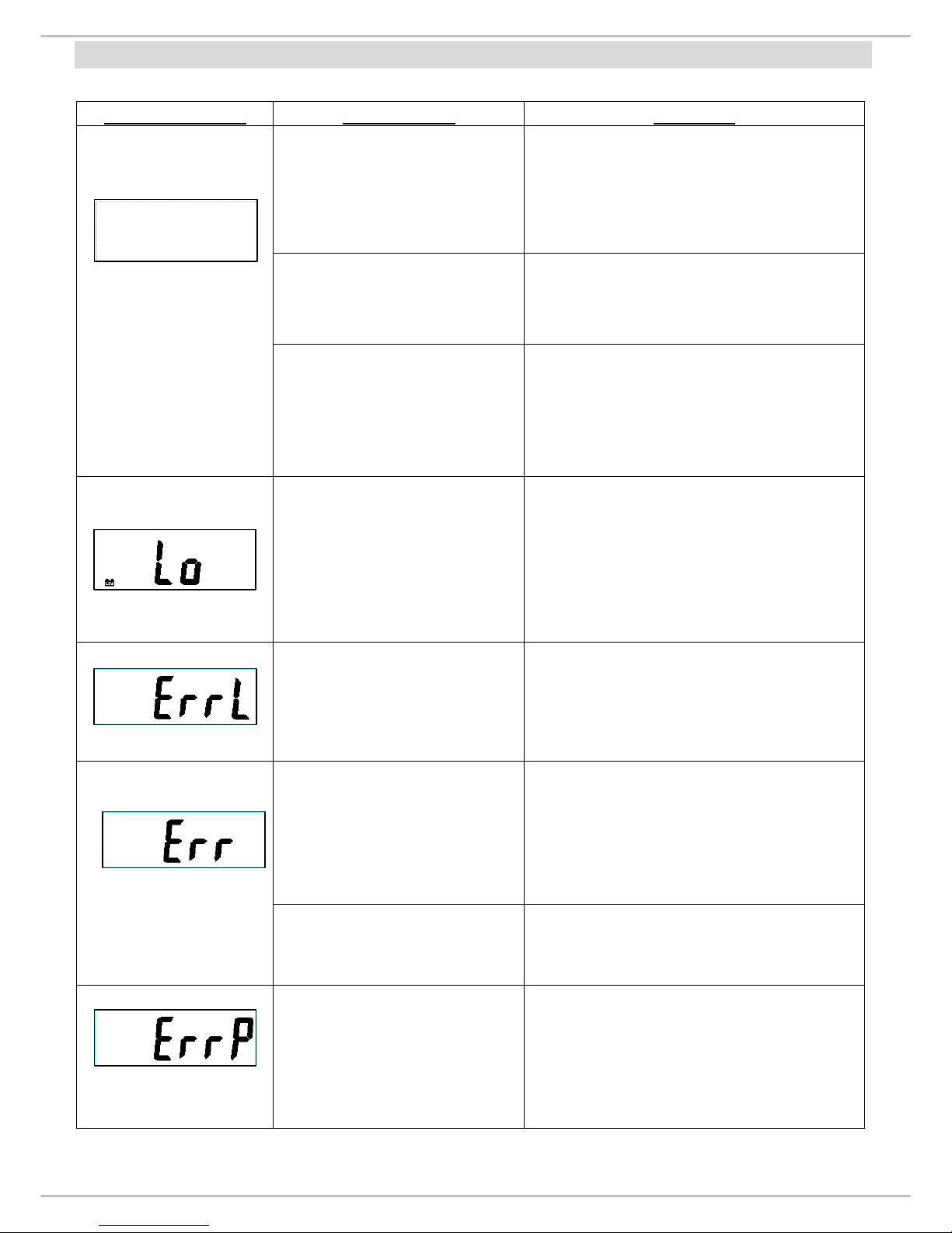
ERROR MESSAGE
Error Message Description Solution
Nothing appears on the
display after pushing
ON/OFF key.
1. Check display.
2. Disassemble indicator.
3. Check wires and control panel.
(refer P.7 & P.9)
Can’t switch on scale
using AAA battery. Battery housing wires are
disconnected or broken. (refer P.7)
Can’t switch on scale
using AC adaptor.
1. AC adaptor damaged.
→Replace adaptor.
2. AC jack wires are disconnected.
(refer P.7)
Low battery indication.
1. Check battery voltage (>6V) and
if needed replace new battery for
operation.
2. If the problem still persists
inspect soldering of controller
PCB or replace the controller
PCB.
Scale zeroed under its
initial balance.
1. Check the load cell and its wiring
(refer P.7).
2. Replace load cell, then re-
calibrate the scale. (for re-
calibrating refer P.17)
Scales zeroed exceed its
initial balance.
1. Remove the weight from scale.
2. Check the load cell’s resistance.
(See P.11)
3. If you change the load cell,
please re-calibrate the scale.
(refer P.17)
Overload 1. Remove the weight from scale.
Overload: Maximum capacity + 9d
EEPROM data incorrect.
1. Check IC3 is soldered or
not.
(Refer P.26 Bottom overlay)
2. Replace controller PCB.
3. Re-c
alibrate the scale. (refer
P.17)
5
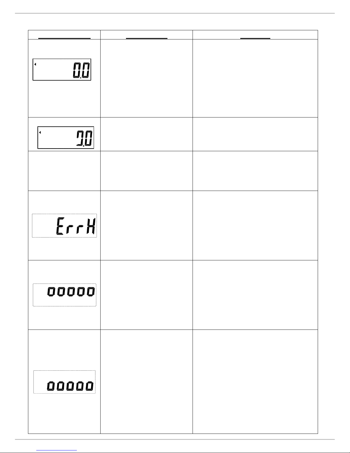
Error Message Description Solution
No weighing.
1. Check the load cell wires are
well and connected to the
correct points. (refer P.7)
2. Check resistan
ces of load cell.
(refer P.11)
3. If you change the load cell,
please re-calibrate the scale.
(refer P.17)
The scale shows non-
complete segments when
power on. Check LCD pin. (refer P.8)
No Current.
1. Check parameters of RS232
interface and pin out. (refer P.19)
2. RS232 wire is disconnected.
(refer P.7)
Count error (too high)
1. Check the load cell wires are
well and connected to the
correct points. (refer P.7)
2. Check load cell for proper bridge
resistances. (refer P.11)
3. Replace load cell, then re-
calibration the scale. (refer
P.17)
Zero count is more than
calibration range (i.e.
10%) while power on.
1. Make sure that the scale
platform doesn’t have any kind
of weight on it.
2. Check the load cell wires are
well connected to the correct
points. (refer P.7)
Re-calibrate the scale. (refer
P.17)
Zero count is less than
calibration range (i.e.
10%) while power on.
1. Make sure that there is no
blocking object (like
paper/plastic sheet or heavy
layer of dirt/dust) between
upper platform of the scale and
the platform on which load cell
is fitted.
2. Check the load cell wires are
well connected to the correct
points. (refer P.7)
3. Re-calibrate the scale. (refer
P.17)
6
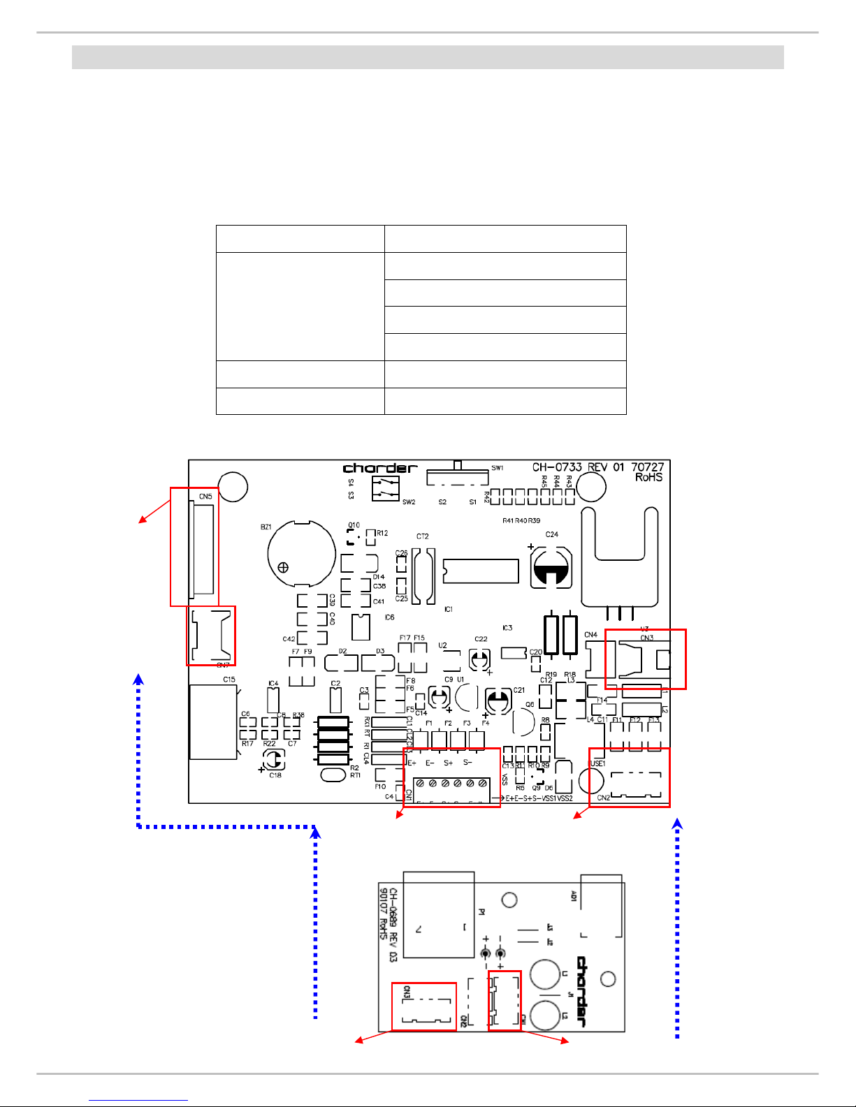
WIRING
ACTION:
1. Remove battery from the scale.
2. Un-screw the lower housing.
3. Remove upper housing.
4. Make sure that all wire connectors are well and that no insulation material is
touching the soldering contacts.
5. Make sure that all wires are connected to the correct points.
Wiring Connector
RED (solder pad “E+”)
WHITE (solder pad “S+“)
YELLOW (solder pad “S-”)
Load cell wiring
(from junction board to
main board)
BLACK (solder pad “E-“)
Battery Wiring CN 3
Power Wiring CN 2
Main Board (CH-0733)
Power Board (CH-0689)
RS 232
connector
Control panel
connector
Load cell
connector Power board
connector
Battery
connector
AC Jack connector (CN 1)
RS 232
connector

7
LCD FORMAT
ACTION:
Problem- The scale shows non-complete segments when power on.
Solution:
•Turn off the scale and take out the batteries from the scale.
•Check LCD pin. (Please refer to above LCD FORMAT)
For instance, if the top left arrow (S1) disappears, then check pin 1 and pin 4.
•Check whether LCD pins are soldered properly or not.
8
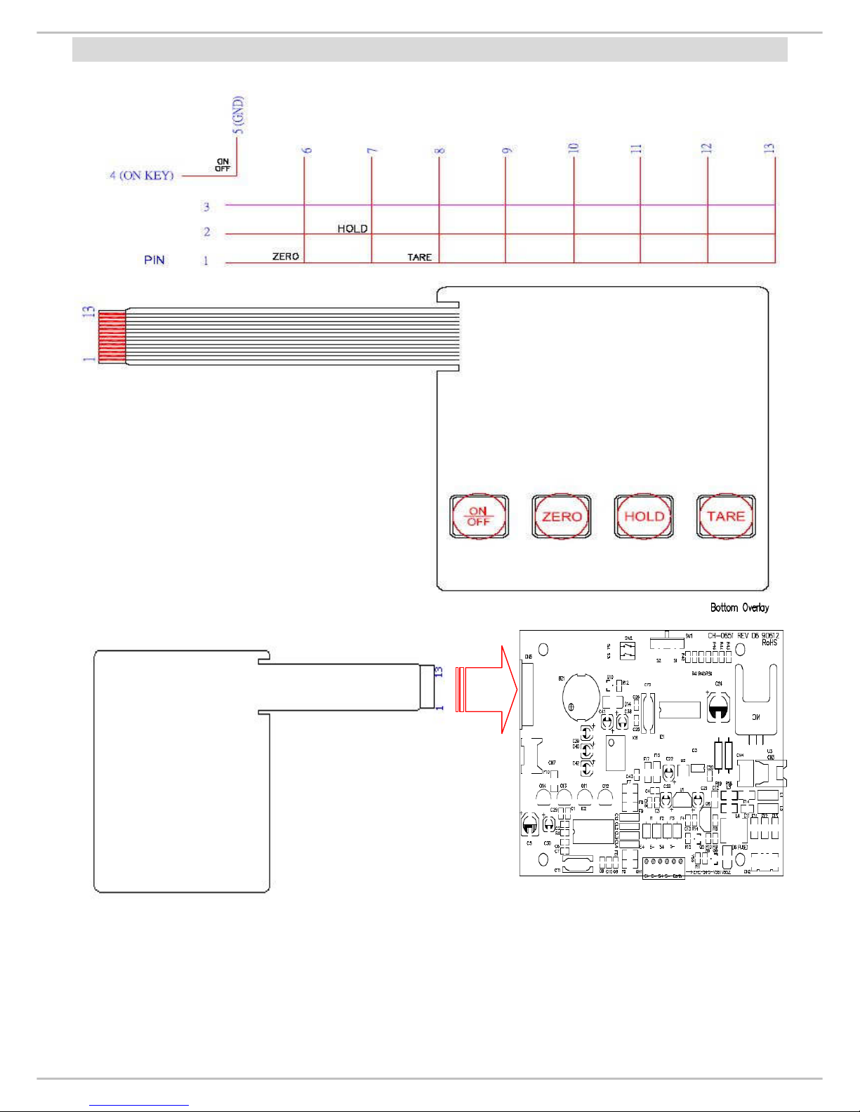
CONTROL PANEL
1. NP4381 (300kg Capacity)
1. Control panel switch damaged.
2. Use multi-meter to measure voltage current of control panel.
3. Reconnect control panel switch.
Make sure that control panel is connected to the correct housing (CN5).
4. If problem persists, replace a new control panel.
9
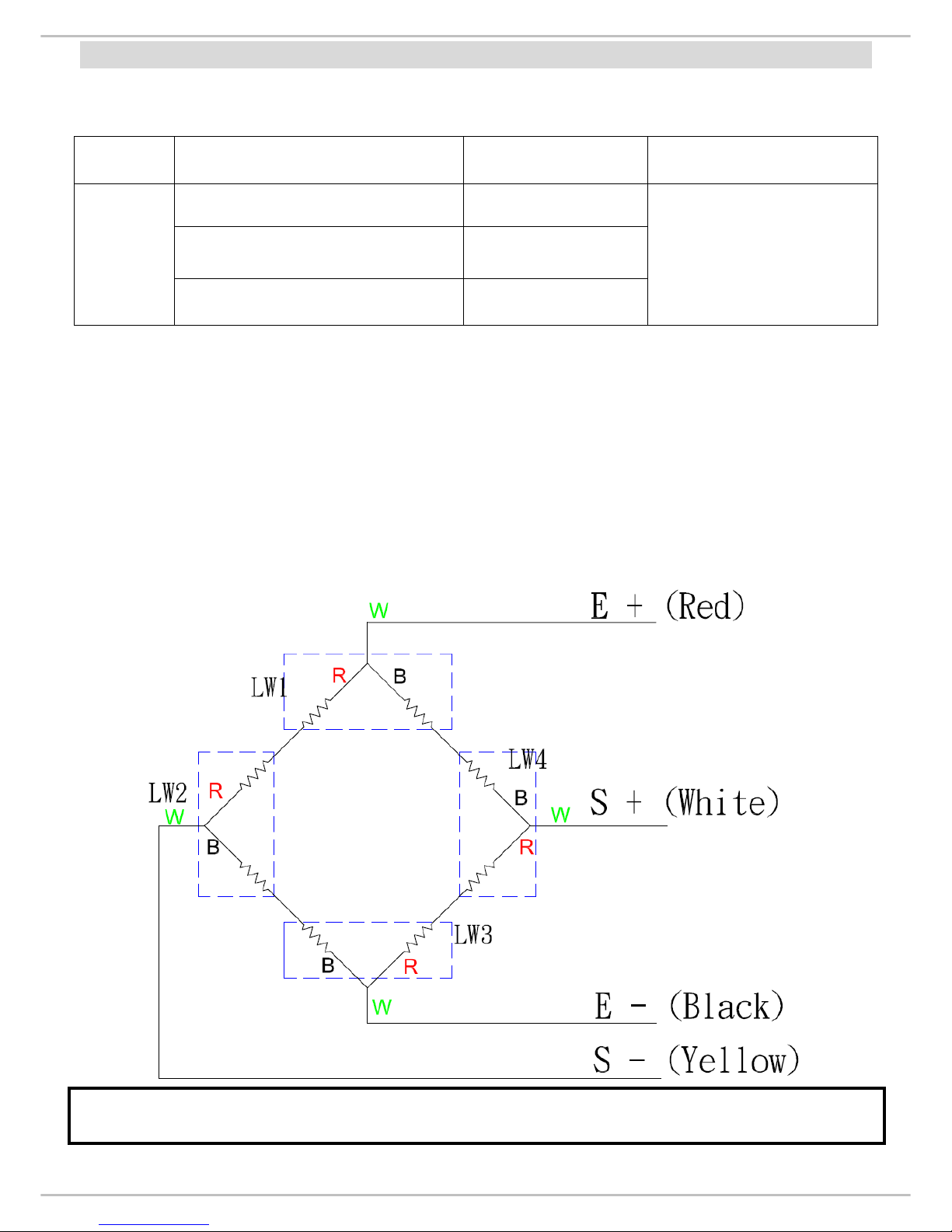
LOAD CELL
Check load cell for proper bridge resistances as below.
MODEL
MEASURING POINTS RESISTANCE REMARK
+E (Red) to -E (Black)
690 ohms minimum
+E (Red) to +S (White)
345 ohms minimum
AL1420A
- E (Black) to +S (White)
345 ohms minimum
Each resistant on load
cell should be same
and the tolerance <
1000 ohms.
ACTION:
1. Remove power (adaptor pin) from the system, check load cell for proper
resistances.
2. If load cell fails the above tests, replace load cell.
3.
If load cell passes the above tests and has no visible damage, please re-calibrate
the scale.
If any of the 4 load cells is broken or damaged, the complete set (all 4 load cells) of load cells
need to be changed.
Other manuals for MS2500
3
Table of contents
Other Charder Scale manuals

Charder
Charder MS-6121R User manual

Charder
Charder MS4640 User manual

Charder
Charder MS2500 User manual

Charder
Charder MS5750 User manual

Charder
Charder R230 User manual

Charder
Charder W320 User manual

Charder
Charder MS5410 User manual

Charder
Charder DP3700 User manual

Charder
Charder MS21NEOV User manual

Charder
Charder MS5810 User manual

Charder
Charder MS 5900 User manual

Charder
Charder MS 4971 User manual

Charder
Charder MS 2400 User manual

Charder
Charder MS 4971 User manual

Charder
Charder R210 User manual

Charder
Charder MS3510 User manual

Charder
Charder MS5810 User manual

Charder
Charder CUPID 3 User manual

Charder
Charder MS4970 User manual

Charder
Charder W310 User manual


