Chenzhu CZLB-80/440 Series User manual

Other Chenzhu Surge Protector manuals

Chenzhu
Chenzhu CZLB-160/440 Series User manual

Chenzhu
Chenzhu GS8515-EX User manual

Chenzhu
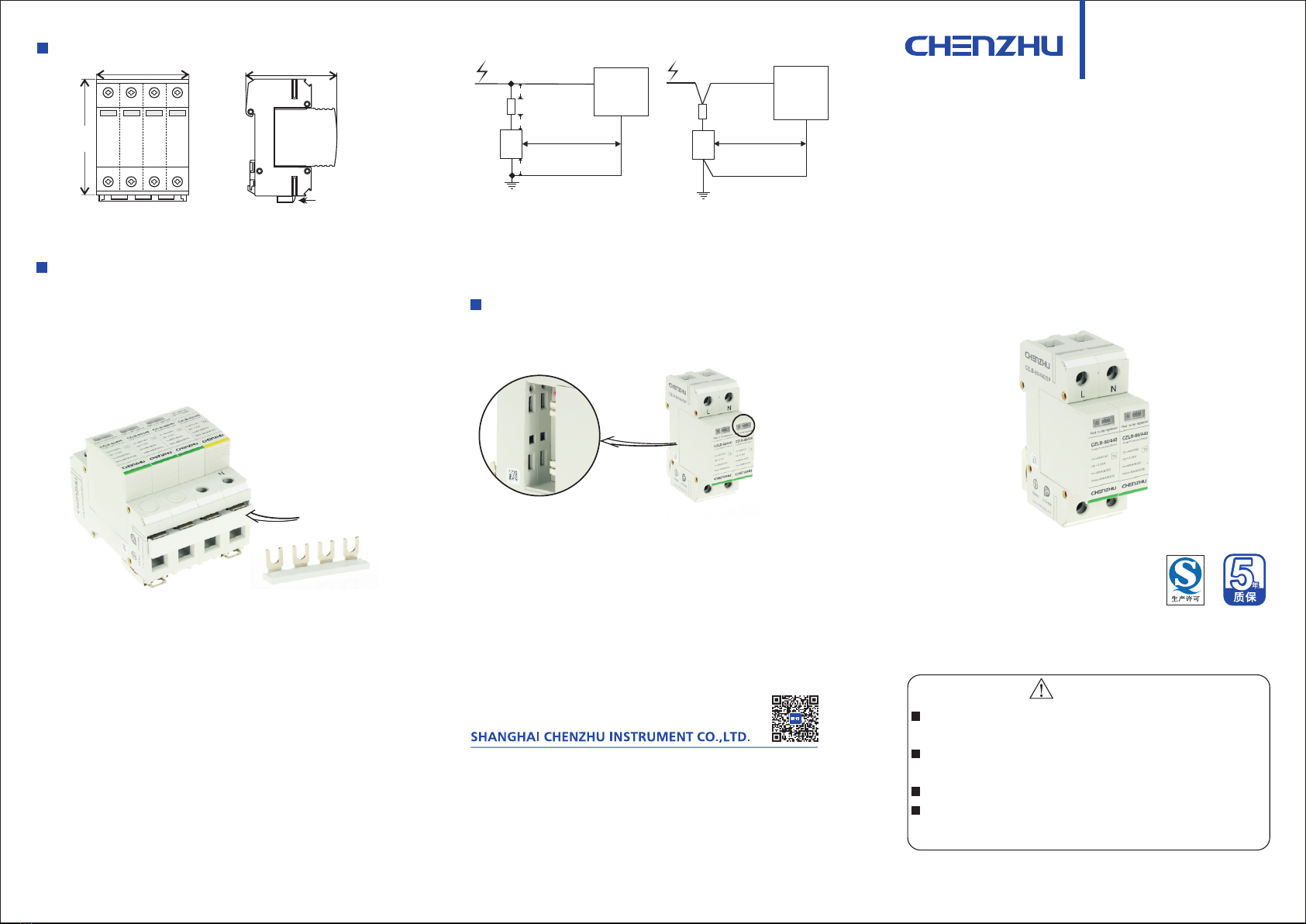
Chenzhu CZLB series User manual

Chenzhu
Chenzhu CZLB-EX Series User manual

Chenzhu
Chenzhu GS8568-EX User manual

Chenzhu
Chenzhu GS8567-EX User manual

Chenzhu
Chenzhu GS8558-EX User manual

Chenzhu
Chenzhu CZLB-160/440 Series User manual

Chenzhu
Chenzhu CZLBX-48-S Series User manual

Chenzhu
Chenzhu CZLBX-48 Series User manual
Popular Surge Protector manuals by other brands

M-system
M-system MDP-JS instruction manual

Patton electronics
Patton electronics 574 user manual

MXPOWER
MXPOWER 120V 15 A user guide

Panamax
Panamax PF Power Max-In-Wall MIW-SURGE-1G installation instructions

Monster Power
Monster Power Home Theatre In-Wall PowerCenter 15 AMP owner's manual

Speco
Speco SPPOEO user manual

Pepperl+Fuchs
Pepperl+Fuchs FIELDBUS manual

Ditek
Ditek D200-120/2083Y Install instructions

Monster
Monster MDP 650 Instructions and warranty information

Outback Power Systems
Outback Power Systems FLEXWARE FW-SP-250 user guide

Bauhn
Bauhn ASPP4-1120 user guide

OPTI-UPS
OPTI-UPS Surge Buster Series SBFH-721 Specifications

INFOSEC UPS SYSTEM
INFOSEC UPS SYSTEM S8 user guide

Amtrol
Amtrol SURGE-TROL SPT-11 Installation & operation instructions

AccelTex
AccelTex ATS-SS-64V-10KA-10GBPS-BT installation guide

Philips
Philips SPP1188WC Specifications

Infinite
Infinite Transtector ALPU installation instructions

Black Lion Audio
Black Lion Audio PG-2 owner's manual