Chenzhu GS8515-EX User manual

CZ.GS8515-EX.11(S)E-5.0/16.04
Connections
Installation
During installation,operation and maintenance,users shall comply with
the relevant requirements of the product instruction manual,GB 50257-
2014"code for construction and acceptance of electric device for explosion
atmospheres and fire hazard electrical equipment installation engineering",
GB 3836.13-2013"Electrical apparatus for explosive gas atmospheres Part
13:Repair and overhaul for apparatus used in explosive gas
atmospheres",GB 3836.15-2000"Electrical apparatus for explosive gas
atmospheres Part 15:Electrical installations in hazardous areas(other than
mines)"and GB 3836.16-2006"Electrical apparatus for explosive gas
atmospheres Part 16:Inspection and maintenance of electrical
installation(other than mines)".
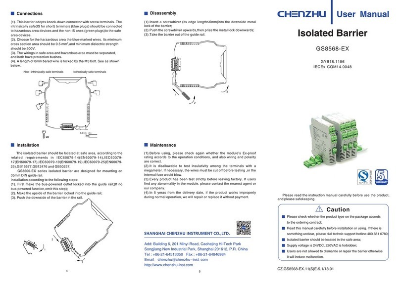
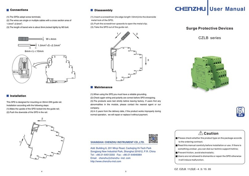
GS8500-EX series isolated barrier are designed for mounting on
35mm DIN guide rail.
Installation according to the following steps:
(1). First make the bus-powered outlet locked into the guide rail;(If no
bus-powered function,omit this step);
(2). Make the upside of the barrier locked into the guide rail;
(3). Push the downside of the barrier in the rail.
5
4
Disassembly
Maintenance
(1)
(2)
(3)
(4)
,
Before using,please check again whether the module s EX-proof
rating accords to the operating ambients,and also wiring and polarity are
correct.
It is disallowable to test insulativity among the terminals with a
megameter.If necessary,the wires must be cut off before testing,or the
internal fuse would blow.
Every product has been tested strictly before delivery.If users
find any abnormality,please contact the nearest agent or our company.
In 5 years from the delivery date,if the product works
improperly during normal operation,we will repair it for free.
(1) Use a screwdriver (edge length≤6mm)insert the metal lock which at
the downside of the isolator;
(2) Push the screwdriver upwards,and pull the metal lock downwards;
(3) Take out the isolator from the rail.
XK06-014-00557
Non-intrinsically safe terminals Intrinsically safe terminals
GS8515-EX
GYB16.1335
Isolated Barrier
Caution
Please check whether the product type on the package accords
to the ordering contract;
Read this manual carefully before installation or using. If there is
anything unclear, please dial technic support hotline-400 881 0780;
Isolated barrier should be located in the safe area;
Supply voltage is 24VDC, 220VAC is forbidden;
Users are not allowed to dismantle or repair the barrier otherwise
it will induce malfunction.
Please read the instruction manual carefully before use the product,
and please safekeeping.
Add: Building 6, 201 Minyi Road, Caohejing Hi-Tech Park
Songjiang New Industrial Park, Shanghai 201612, P.R. China
Tel : +86-21-64513350 Fax : +86-21-64846984
Email:chenzhu@chenzhu-inst.com
http://www.chenzhu-inst.com
1
2
3
M3
8.0
3
2
1
(1)
(2).
(3).
(4).
. This barrier adopts knock-down connector with screw terminals. The
intrinsically safe(IS for short) terminals (blue plugs) should be connected
to hazardous area devices and the non-IS ones (green plugs)to the safe
area devices.
Choose for the harzardous area the blue-marked wires. Its minimum
2
cross section area should be 0.5 mm ,and minimum dielectric strength
should be 500V.
The wirings in safe area and hazardous area must be separated,
and both have protection bushes.
A length of 8mm bared wire is locked by the M3 bolt. See as shown
below.

Number of channels: 1/2
Supply Voltage: 20~35V DC
Current consumption:(at 24Vdc supply,relay energized)≤50mA
Safe-area output:
Drive ability: 250V AC,2A or 24V DC,2A
Load type: resistive
Delay time: 0.5s,10s(Adjustable switch delay)
Hazardous-area input:
Control input: ON/OFF control(9,10)
Upper limit/lower limit control(9,10,11)
Sensitivity: 1k~150kΩ(adjustable via the front cover potentiometer)
The property of input and output:
If liquid level exceeds limit:
When K1 is set to OFF state, output relay is energized, with yellow
LED ON.
When K1 is set to ON state, output relay is de-energized,with yellow
LED OFF.
When LFD enabled, output relay 1 is de-energized,with yellow LED
OFF and red LED flashing; output relay 2 is energized, with yellow LED
ON.
Function of the control switch:
Note: A 430kΩresistor should be paralleled between electrodes when
using LFD functing.
NO means terminals 6,8 and 3,5.
NC means terminals 6,7 and 3,4.
The switches are set to OFF state by default.
Power supply protection:
protect the product form reverse supply voltge destroy.
Electromagnetic compatibility:
Accord with IEC 61326-1(GB/T 18268)
Dielectric strength:
Between non-intrinsically safe circuit and intrinsically safe≥2500V AC
Between power supply and non-intrinsically safe circuit≥1500V AC
Insulation resistance:
Between non-intrinsically safe part and intrinsically safe part≥100M
Between power supply and non-intrinsically safe part≥100M
Weight: approx.150g
Suitable location:
Mounting in safe area, be connected with IS apparatus in zone 0/1/2,
ⅡA,ⅡB,ⅡC,T4~T6 hazardous area.
Suitable IS apparatus: Conductive liquid level detection devices
Ω
Ω
1 2 3
Summarize
Specification
Operation Conditions
(1).The air should not contain any medium corrupting the coat of chrome,
nickel and silver. Moreover,violent quiver and impact or any cause of
electromagnetic induction (such as big current or spark, etc.)must be
avoided when using.
(2). Operating temperature: -20℃~+60℃
(3). Storage temperature: -40℃~+80℃
(4). Relative humidity: 10%~90%
Application
Outline dimensions
118.9mm×106.0mm×17.5mm
Intrinsic safety explosion protection loop system
Special requirements have to be confirmed before using the intrinsically
safe explosion loop system(intrinsically safe circuit) which connected by
isolated barrier and intrinsically safe apparatus in field:
(1) The explosion level of intrinsically safe apparatus should meet the
requirements of operation conditions. The apparatus should pass the
explosion protection test and get the certificate by state-authorized
explosion-proof product certification bodies.
(2) The intrinsic safety parameters of isolated barrier and intrinsically
safe apparatus both are sure, and comply with 12.2.5 of GB 3836.15-2000.
(3) If any parameters are unclear, the system has to be confirmed by
state-authorized explosion-proof product certification bodies.
Intrinsic safety description
GS8515-EX level control isolated barriers are used to monitor and
regulate the level of conductive liquids. AC voltages are provided in the
probe circuit. They measure the resistance between two probes in the
liquid. Relay outputs can be set as normal close(NC) mode or normal
open(NO) mode. Line Fault (breakage) Detection is selectable.
National Supervision and Inspection Center for Explosion Protection and
Safety of Instrumentation(NEPSI)
Compliancy with standard: GB3836.1、GB3836.4 and GB3836.20
Ex-marking: [Ex ia Ga] ⅡC
Um=250V
Intrinsic safety parameter: (9,10,11 terminals)
(1) for distributed inductance and capacitance e.g. as in a cable, allow
the values of capacitance and inductance;
(2) for circuits containing up to 1 % inductance or up to 1% capacitance
with a cable,allow the values of capacitance and inductance;
(3) for connection of the combined inductance and capacitance where
both are greater than 1% of the allowed value (excluding the cable), allow
up to 50% each of the values of capacitance and inductance
Uo=5.4V, Io=2.5mA, Po=6.25mW
ⅡC:Co=65μF , Lo=100mH
ⅡB:Co=400μF , Lo=400mH
ⅡA:Co=1000μF , Lo=900mH
Safe-area
Hazardous-area
10
9
430K 430K
430K
9
GS8515-EX
7
8
9
10
1(+)
2(-)
5
3
-+
11 6
4
Lower
limit
Upper
limit
Power supply
Power supply
OUT1
OUT2
IN OUT
10
ON
K1
LFD Enabled
Sta.
Open
Close
OFF
LFD Disenabled
K2 K3
Delay 0.5s
Delay 10s
Other Chenzhu Surge Protector manuals
Chenzhu
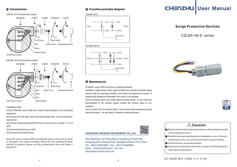
Chenzhu CZLBX-48-S Series User manual
Chenzhu
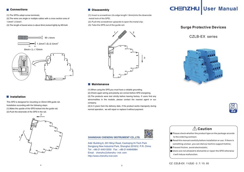
Chenzhu CZLB-EX Series User manual
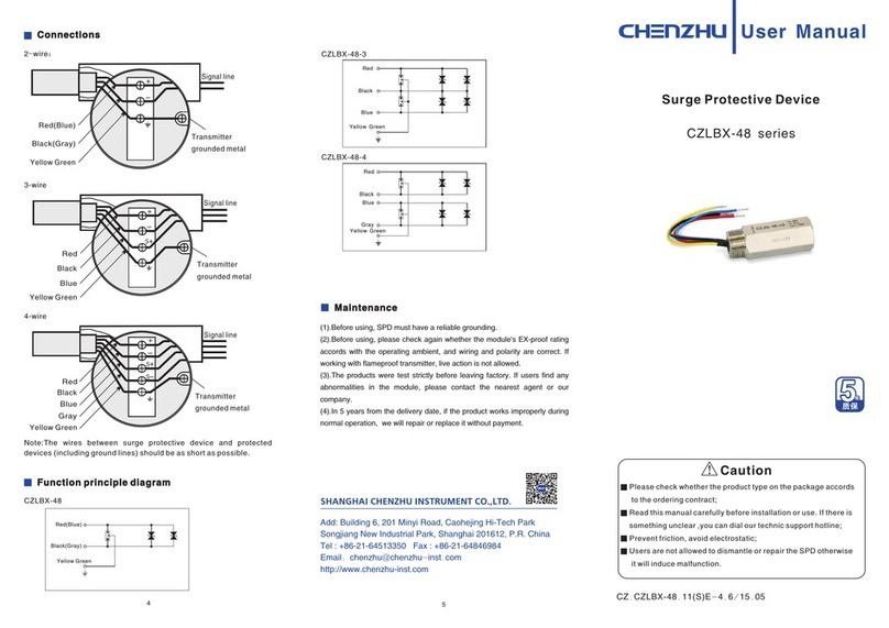
Chenzhu
Chenzhu CZLBX-48 Series User manual
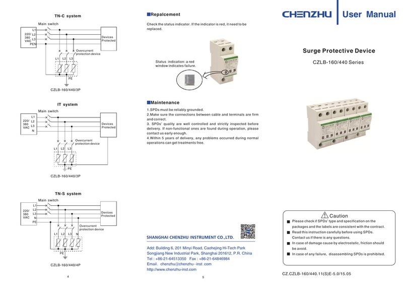
Chenzhu
Chenzhu CZLB-160/440 Series User manual
Chenzhu
Chenzhu GS8567-EX User manual

Chenzhu
Chenzhu GS8558-EX User manual
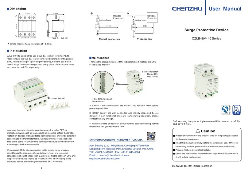
Chenzhu
Chenzhu CZLB-80/440 Series User manual

Chenzhu
Chenzhu CZLB-160/440 Series User manual
Chenzhu
Chenzhu GS8568-EX User manual
Chenzhu
Chenzhu CZLB series User manual
