Nominal operating
voltage Un
Nominal discharge
current In(8/20μs)
Parameter
Protection level Up
(80kA,8/20μs)
Response time
Leakage current
Status indication
Over current protection
Connection cable
sectional area L/N
Max. operating
voltage Uc
Max. discharge
current Imax(8/20μs)
Connection cable
sectional area PE
CZLB-160/440
440V AC
80kA
160kA
220V AC
<25ns
<20 Aμ
Blank: Ok
Red: failed
200A
2
≥6mm
2
≥10mm
15kA
255V AC
50kA
160kA
<100ns
CZLB-160/255
255V AC
-
-
-
2
≥6mm
2
≥10mm
80kA
SPD module
2.8kV 2.5kV
Impulse current
Iimp(10/350μs)
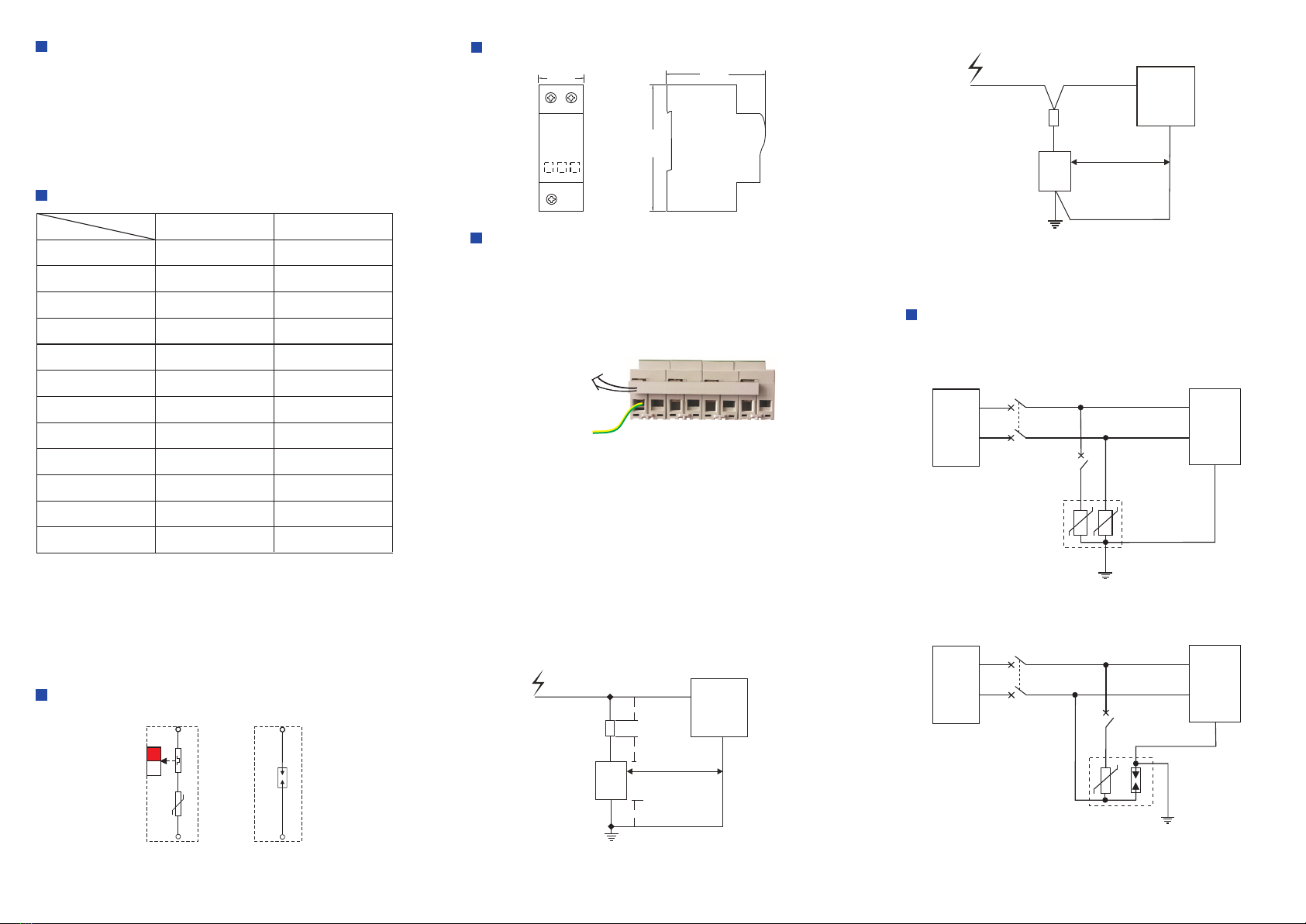
Typical applications
Single phase system
Main technical parameters
Installation
Normal connection
Dimension
When install SPDs, the connection cable should be as short as
possible. As the diagrams shown below, L( in normal
connection) should be less than 0.5 meters. Cable between SPD
and the protected device should be less than 10m. The housing of
the protected device should be grounded via SPD terminals.
L=a+b+c
In case of the main circuit broken because of a failed SPD, a
protection device such as air switch or fuse should be installed
before the SPDs. According to our tests, protection devices with a
nominal current of 100A are recommended. The cross sectional
area of the upper (for L/N connection) cable should be no less than
2
6mm and the cross sectional area of the cable for grounding should
2
be no less than 10mm .
PE
L
N
220VAC
Main switch
Overcurrent
protection device
Devices
Protected
General
1 2 3
CZLB-160/440/2P
CZLB -160 /440 series AC power supply SPDs are designed
according to the domestic criterials. It enables the connection
between the power supply system and an equipotential network
instantaneously when the surge occurs and limit the residual voltage
to a certain level to protect the devices protected. Normally, it is
used in lighting protection zone 1. For better protection effect, SPDs
with different protection levels should be used downstream.
Schematic diagram
CZLB-160/440 series SPDs are delivered in single pieces. They
should be connected by a bus-bar and then you can choose any
piece for ground connection. Otherwise you need to ground all
pieces. Loosen all the screws completely before you put the bar in
and then tighten the screws except the one you chose for ground
connection.
Bus Bar
Grounding Calble
V connection
Overcurrent
protection device
SPD
C
L
Devices
Protected
<10m
Surge
SPD
Devices
Protected
C
b
a
c
Surge
LN
PE
L/N
Red
Blank F1
Rv
CZLB-160/440
N
PE
GDT
CZLB-160/255
Operation temperature: -40℃-70℃
Relative humidity: 10%-90%
Housing protection level(IEC60529): IP 20
Housing material flame-retarded level(Ul94): PA66/V0
Installation: Standard 35mm DIN rail
Testing standards: GB 18802.1/IEC 61643-1
Performance test: Shanghai Lighting Protection Center
36mm 67mm
91mm
<10m
Overcurrent
protection device
PE
L
N
220VAC
Main switch
Devices
Protected
Overcurrent
protection device
CZLB-160/440/1P+1


