CHIAROSCURO ST50 Operating instructions

ST50 - ST100
CSG2 “DEAD-MAN” COMMAND
Cod.
220517
CHIAROSCURO SAS
di Girelli Marco & C.
C.so General A. Cantore 23 - 38061 Ala (TN) Italy
P.I. IT01527050221
Pag.
1 di 32
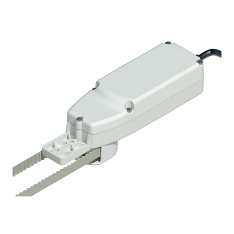
ACTUATOR FOR CASEMENT BLINDS
USER AND MAINTENANCE MANUAL
English version
This user manual is an integral part of the machine and must be kept in a suitable place so that it
remains intact and can be consulted throughout the life of the ma
chine.
The manufacturer is entitled to make changes to the production and the manual, without this implying an
obligation to update the previous production and manuals.
.

ST50 - ST100
CSG2 “DEAD-MAN” COMMAND
Cod.
220517
CHIAROSCURO SAS
di Girelli Marco & C.
C.so General A. Cantore 23 - 38061 Ala (TN) Italy
P.I. IT01527050221
Pag.
2 di 32
PREFACE
Dear customer, we thank you for your choice of our equipment, which will certainly prove to be important,
especially over time. We invite you to carefully follow the instructions given in this manual, which will help
you to use your equipment in the best possible way and to maintain its characteristics over time.
CHIAROSCURO SAS di Girelli Marco & C.
1. GENERAL INFORMATION
This user manual is an integral part of the equipment and constitutes the indispensable support for its
installation and correct use. Read it carefully and completely before installing and using the equipment.
The manual must accompany the equipment in the event of resale. Partial or total reproduction of this
document is forbidden without the written authorisation of CHIAROSCURO SAS.
1.1 DEFINITIONS AND SYMBOLS
The following paragraphs provide a set of definitions, terminologies and symbols used in the drafting of
this manual.
S
IMBOLO
D
ESCRIZIONE
User: (U.) unskilled operator capable of operating the equipment under normal
operating conditions and for simple maintenance tasks.
Electromechanical operator: (O.E.) technician able to install mechanical - hydraulic -
pneumatic components and to carry out adjustments, maintenance or repairs and to
work in the presence of voltage inside cabinets, junction boxes and electrical
installations.
Manufacturer's technician:(T.C.) qualified technician made available by the
manufacturer to carry out operations of a complex nature in particular situations or, in
any case, as agreed with the user. The skills are, as appropriate, mechanical and/or
electrical and/or electronic and/or software.
Note: Indicates important indications or information contained in the manual which
should be read, with particular attention, for the best use of the equipment.
Danger: Indicates a situation that could lead to injury, even death, or serious damage to
health.
Attention: Indicates a situation that could cause, even indirectly, damage to persons,
property and the environment, including economic consequences.
Warning: Indicates that particular attention must be paid to the indications. Failure to
do so may lead to malfunctions or dangerous conditions or damage.

ST50 - ST100
CSG2 “DEAD-MAN” COMMAND
Cod.
220517
CHIAROSCURO SAS
di Girelli Marco & C.
C.so General A. Cantore 23 - 38061 Ala (TN) Italy
P.I. IT01527050221
Pag.
3 di 32
2. IDENTIFICATION OF THE MANUFACTURER
The nameplate attached to the top of the actuator contains all the identification data of the ST50/ST100
actuator.
Fig.3.1 Example of a label (the data shown are purely indicative, the actual values are shown on the
equipment label on the automation itself).
2.1 INFORMATION ON TECHNICAL SUPPORT AND MAINTENANCE
Please contact the Service Centre to report faults:
CHIAROSCURO SAS di Girelli Marco & C.
C.so General A. Cantore 23 - 38068 Ala (TN) Italia
Tel : +39 0464 424715 fax : +39 0464 712027
For communications, information requests or any orders for accessories or spare parts, please send your
requests to info@chiaroscuro.eu
On the label, applied to all drives, are indications regarding
the model of automation used, power supply voltages,
absorption, speed of movement, degree of electrical
protection, operating temperatures, batch number and
year of manufacture of the automation and compatibility
with the European mark. .
During the period of validity of the Guarantee, the customer must scrupulously follow the
instructions given in this manual. Failure to do so will invalidate the warranty and will not
result in any problems or malfunctions of the equipment (please read the warranty
conditions attached to this manual carefully).
The manufacturer, in order to adapt the equipment to technological progress and specific
production requirements, may decide, without prior notice, to make changes to the
equipment without any obligation to update the previous production and manuals.
Furthermore, if the illustrations in this manual differ slightly from the equipment in your
possession, the safety and operating instructions of the same are always guaranteed.

ST50 - ST100
CSG2 “DEAD-MAN” COMMAND
Cod.
220517
CHIAROSCURO SAS
di Girelli Marco & C.
C.so General A. Cantore 23 - 38061 Ala (TN) Italy
P.I. IT01527050221
Pag.
4 di 32
3. FEATURES AND TECHNICAL INFORMATION
MODEL ST50.2A ST50.1ASX/DX ST100.2A
ST100.1A
SX/DX
Number of doors
2 1 sx / 1 dx
2
1 sx / 1 dx
Min-max wall opening width
80-160 cm - 2 doors
60 - 80 cm - 1
door
160-250 cm - 2
doors
80 - 125 cm - 1
door
Max. surface
3,6 mq - 2 doors 1,8 mq - 1 door
5 mq – 2 doors
2.5 mq – 1 door
Max. door weight
70 kg
140 Kg
Dimensions LxHxD
77x67x800 /
1600 mm
77x67x600 /
800 mm
77x67x1600 /
2500 mm
77x67x800 /
1250 mm
Power supply voltage
110 ÷ 230 VAC
Max. current consumption
~ 0,45 A
Obstacle detection impact
force < 150 N
Max. torque
50 Nm
100 Nm
180° manoeuvre time
25 sec. - 2 ante 20 sec. - 1 anta
50 sec. – 2 ante
40 sec. – 1 anta
Working cycle
20 cycles/hour
Limit switch adjustment
With thrust control
Degree of protection of
electrical devices
IP 32
Irreversible arm
Standard
Housing colour
Matt white Ral 9010 / Matt black Ral 9005
Articulation colour
Matt black Ral 9005 / Matt white Ral 9010
Housing and articulation
colour Ral at choice No, natural aluminium casing and silver galvanised joint available
Electric lock
yes on request applicable to window sill/threshold
Integrated radio receiver
yes on request also available separately
The blind develops a maximum torque of 50 Nm. with ST50 and 80 Nm. with
ST100. If there are obstacles or wind in the way of the movement of the sash,
the automation blocks the motor drive for safety.

ST50 - ST100
CSG2 “DEAD-MAN” COMMAND
Cod.
220517
CHIAROSCURO SAS
di Girelli Marco & C.
C.so General A. Cantore 23 - 38061 Ala (TN) Italy
P.I. IT01527050221
Pag.
5 di 32
3.1 LEGAL REFERENCES
The legislative references applied and the national and harmonised technical standards applied for
compliance with the legislative references above are:
Year of construction from 2019
Meet the applicable essential requirements of the Machinery Directive 2006/46/EC, Annex I
Art. 1.1.2, 1.1.
3, 1.1.5, 1.2.1, 1.2.3, 1.2.6; 1.3.2, 1.3.4, 1.3.9 ; 1.5.1, 1.5.7, 1.5.8, 1.5.9, 1.5.10, 1.5.11 ;
1.7.1, 1.7.1.1, 1.7.3, 1.7.4.2, 1.7.4.3
The relevant technical documentation shall be compiled according to Annex VII, section B
The person authorized to constitute the relevant technical documentation is: Girelli Marco
Upon a suitably substantiated request from the national authorities, the above technical documentation
will be made available, via e-mail, within a time compatible with its importance.
In addition, the above-mentioned product complies with the relevant provisions of the following
Directives:
1. - 2014/30/EU Electromagnetic Compatibility Directive
2. 2014/35/EU Low Voltage Directive (LVD)
3. - 2011/65/EU Directive on the restriction of the use of certain hazardous
substances in electrical and electronic equipment (RoHS Directive)
4. - 2015/862/EU Delegated Directive amending Annex II to Directive
2011/65/EU of the European Parliament and of the Council with regard to
the list of substances with restricted use
5. Translated with www.DeepL.com/Translator (free version)
And of the following harmonized standards and/or technical specifications:
EN 60335-2-103; EN 61000-6-3:2007 + A1:2011 + AC:2012; EN IEC 61000-6-2:2019
EN60335-1:2012 + AC:2014 + A11:2014; EN 50581:2012
At the customer's request, a version of the ST50/ST100 system is available equipped with a
radio receiver module and transmitters operating in the 433MHz band in compliance with
the requirements of Directive 1999/95/EC (radio and telecommunications equipment) and
subsequent amendments
4. GENERAL DESCRIPTIONS
The ST50/ST100 is an automation for opening/closing hinged shutters (frames). It consists of a high-
performance non-reversible automation coupled with highly resistant metal gears. The possibility of

ST50 - ST100
CSG2 “DEAD-MAN” COMMAND
Cod.
220517
CHIAROSCURO SAS
di Girelli Marco & C.
C.so General A. Cantore 23 - 38061 Ala (TN) Italy
P.I. IT01527050221
Pag.
6 di 32
closing or opening with simple manual controls placed in remote positions (remote control) or with
automation systems (home automation) allows the user to make the most of the protection offered by the
shutters in the various environmental conditions present (e.g. hot, cold, protected from insects, etc.).
5. RECEPTION AND STORAGE
5.1 CONTROL ON RECEIPT OF EQUIPMENT
On receipt of the equipment, remove the packaging and check the integrity of the contents.
5.2 CONTENTS OF THE BOX:
1 Pz.1
Automation with telescopic cover complete with standard slotted arms
2 Pz.1
Technical installation manual
3 Pz.10
Fischer kit, screws for fixing aluminium base (screw + dowel + washer).
4 Pz.6
Countersunk flat head screws with cross, size 3.5x25 for fixing sliding rails
5 Pz.2
Standard slotted joint complete with forearm and end piece (accessory bracket)
6 Pz.2
Sliding rails, length 80 cm. (optional to customer size)
7 Pz.2
Semi-rigid cardboard template for making holes in the upper vault
8 Pz.3
Wedges for carter opening

ST50 - ST100
CSG2 “DEAD-MAN” COMMAND
Cod.
220517
CHIAROSCURO SAS
di Girelli Marco & C.
C.so General A. Cantore 23 - 38061 Ala (TN) Italy
P.I. IT01527050221
Pag.
7 di 32
If the product, upon receipt, is damaged and/or has missing parts and/or defects/malfunctions
are detected, do not attempt to repair the equipment, but contact the service centre, indicating
the model, code and serial number of the equipment (see chapter "Manufacturer's
identification").
It is compulsory to use the screws supplied for fixing the joints and the slider. The package
includes the basic supply of screws for fixing to the ceiling and specific screws for fixing the track
to wooden sashes: for this type only, the installer may assess the integration and use of
complementary screws, provided that these screws respect the dimensional characteristics of
those supplied and that they allow the inspection, disassembly and maintenance of the product
(the use of turbo screws is not permitted).

ST50 - ST100
CSG2 “DEAD-MAN” COMMAND
Cod.
220517
CHIAROSCURO SAS
di Girelli Marco & C.
C.so General A. Cantore 23 - 38061 Ala (TN) Italy
P.I. IT01527050221
Pag.
8 di 32
5.3 STORAGE
6. MECHANICAL ASSEMBLY INSTRUCTIONS
Electromechanical operator: (O.E.) a technician able to install mechanical - hydraulic -
pneumatic components and to carry out adjustments, maintenance or repairs and to work
in the presence of voltage inside cabinets, junction boxes and electrical installations.
The automation supplied is a professional product for free installation. Installation must be
carried out by a qualified electromechanical operator. CHIAROSCURO SAS is exempt from
any liability in the event of incorrect installation and/or installation by unqualifie
d
operators.
6.1 TOOLS REQUIRED FOR ASSEMBLY
The following tools and materials are required for installation:
Drill / Hammer drill
Power and control cable 4x1
Screwdriver
Phillips and slotted screwdriver
Wall drill diam. 8mm.
Screwdriver with Allen insert no. 4
Iron drill diam. 4mm.
Scissors for template cutting
If the equipment is not used for a long period of time, store it in a dry, clean and dust-
free
place.
In the ev
ent of material storage exceeding 24 months from the date of registration,
CHIAROSCURO SAS will provide the Warranty provided for in the General Conditions of Sale.
(DO NOT use drills or impact wrenches to fix the aluminium bases. Use clutched drills/screws
only. Do not exceed 150MPa of pressure on the material).
The list shown is not supplied with the ST40 product, but is necessary for correct
installation
on the bench. D.P.I. or other is the responsibility of the O.E. depending on the field
installation itself.

ST50 - ST100
CSG2 “DEAD-MAN” COMMAND
Cod.
220517
CHIAROSCURO SAS
di Girelli Marco & C.
C.so General A. Cantore 23 - 38061 Ala (TN) Italy
P.I. IT01527050221
Pag.
9 di 32
6.2 IDENTIFYING THE TYPE OF APPLICATION
6.3 WARNING FOR INSTALLATION TYPES 4,5,6 AND DERIVATIVES
Particular care must be taken when the net passage clearance is between 80 and 90cm and the A2
shoulder dimension is greater than 12cm.
It is advisable to position the slider in the track so that when the sash is open it is at least 8 mm from the
end of the track. Make sure that the 90° end does not touch the sash (recommended minimum distance of
5mm).

ST50 - ST100
CSG2 “DEAD-MAN” COMMAND
Cod.
220517
CHIAROSCURO SAS
di Girelli Marco & C.
C.so General A. Cantore 23 - 38061 Ala (TN) Italy
P.I. IT01527050221
Pag.
10 di 32
In order to increase this distance, you can use the adjustment slots on the 90° end and on the forearm. In
general, the articulated arm must always have enough space to extend when closing. Installations with L1
(light inside the window) smaller than 80cm/160cm are only possible after checking with the
"Chiaroscuro" technical office. If A2 is larger than 12cm, it may be necessary to distance the automation a
few centimetres from the window wall abutment (Dimension A1, see previous drawing) to avoid contact
between the 90° terminal and the sash.
.
• If there is limited space available between closed shutters and closed glazing - distance "D5" - or if the
maximum permitted D = 200 mm is to be used, distance "D1" can be reduced by up to 2 mm so that guide
rail 2 in closing will have to pass under the arm and distance "D6" will be approx. 20 mm.
• The length of the 90° terminal "t1", for TIP.1, 2 and 3, is designed so that when the sash is closed the
articulated arm fits into the 77 mm space occupied by the motor unit. In the case of particular sash shapes,
TIP.4, 5, and 6, it is necessary to use a 90° Padovian terminal, extended to prevent the arm from touching
the sash at point "P" - the edge of the hinge - before completing the opening stroke. The 90° Padovian
terminal increases the overall dimensions of the closed joint to 120 mm instead of 77 mm. Please note that
when using the 90° padovan terminal, if the distance "D" is already max. 200 mm, the dimension "D4+D2"
could be greater than 400 mm to allow the articulated arm to extend when closing.
MAXIMUM WIDTH
DMAX MM.
The values in the table are valid for doors with a thickness of 40 mm,
type 4,5, 6 and derivatives. A margin of at least 5 mm should always be
kept in relation to the values in the table. In cases where the values are
below 5 mm, it is preferable to proceed with a dimensional test in the
field and/or on a sample to establish with certainty whether the space
available is sufficient to move the shutters correctly.
900 200
850 150
800
120

ST50 - ST100
CSG2 “DEAD-MAN” COMMAND
Cod.
220517
CHIAROSCURO SAS
di Girelli Marco & C.
C.so General A. Cantore 23 - 38061 Ala (TN) Italy
P.I. IT01527050221
Pag.
11 di 32
The thrust efficiency of the motorisation improves as the "X" measurement increases, which is the
distance measured on the vertical axis between the fulcrum of rotation of the motor arm and the slider
located on the track, and the position of the slider with respect to the hinge. Bear in mind that the more
the slider is moved towards the centre of the sash, the greater the opening efficiency of the motorisation.
Moving the drive towards the centre of the window increases the efficiency of the drive, but at the same
time increases the overall length of the joint. During installation, once the position of the motor has been
determined from the wall abutment and with respect to the shutter, open the sash and ensure that the
end joint is as extended as possible, guaranteeing a minimum distance between the joint and the shutter
of at least 5mm at each point of rotation of the sash..
It should be noted that the ST50/ST100 product is specifically for casement windows and doors.
Any other use does not guarantee correct functioning and compatibility with CE marking.
7. ARTICULATION DETAILS
Article 1
Standard slotted forearm
Article 2
Standard slotted terminal
Article 3
Extended slotted terminal (compulsory accessory in the Padua version)
Article 4
Extended slotted arm (compulsory accessory in the Padua version)

ST50 - ST100
CSG2 “DEAD-MAN” COMMAND
Cod.
220517
CHIAROSCURO SAS
di Girelli Marco & C.
C.so General A. Cantore 23 - 38061 Ala (TN) Italy
P.I. IT01527050221
Pag.
12 di 32
8. CHOICE OF APPLICATION TYPE
SIDE-BY-SIDE GUIDANCE
Position the drive as shown in the adjacent figure.
There must be approximately 20 mm between the
automation and the internal edge of the leaf. If, for
various installation reasons, this distance is
exceeded, you must:
•In any case, make sure that you comply with the
specifications given in the drawing in chapter
"Installation note".
•Please note that increasing the distance reduces
the thrust on the sash.
GUIDE BELOW
Position the motor flush with the leaf as shown. The
guide must be positioned under the automation as
shown in the figure. Between the leaf and the
automation, leave a space that prevents the leaves
from coming into contact with the automation
when they are fully closed.
RECESSED AUTOMATION
Depending on the type of material your lintel is
made of, the distance between the edge of the wall
and the drive can vary, but must never be less than
40 mm. If this measurement increases, remember
to check that the dimensions given in chapter 7.3
are respected.
Mounting accessories:
Sheet metal for flush-mounting omega plate for
fastening the automation (only with side-by-side or
underneath rail)

ST50 - ST100
CSG2 “DEAD-MAN” COMMAND
Cod.
220517
CHIAROSCURO SAS
di Girelli Marco & C.
C.so General A. Cantore 23 - 38061 Ala (TN) Italy
P.I. IT01527050221
Pag.
13 di 32
9. PHYSICAL INSTALLATION OF THE AUTOMATION
9.1 CHECKING DOOR MOVEMENT AND FIXING
The automation you are installing incorporates a safety device which, by detecting obstacles, stops the
movement of the leaves. For this reason, it is necessary to check it before installing the automation,
9.2 CHECKING DOOR MOVEMENT AND FIXING
The automation you are installing incorporates a safety device that, when it detects obstacles, stops the
movement of the leaves. For this reason, even before installing the automation, it is necessary to check
that the leaves have compatible characteristics, as indicated in the table in chapter 7 (in particular, the
maximum leaf weight of 70 kg/140 kg and the maximum leaf surface area, which must not exceed 1.8
sq.m./2.5 sq.m. for each leaf). These indications are not exhaustive: for further information please refer to
chap. 22. It is also necessary to check the rotation of the leaves, which must rotate fluidly, free and
unobstructed. We suggest carrying out this check by closing the leaf and pushing it from the closed
position. With a normal push, the leaf should open fully until it touches the opposite wall. If the shutter
shows some friction in its movement, it is necessary to suspend the assembly phase of the automation and
intervene on the hinges and elements of the shutter that compromise the fluidity of movement, making
the appropriate changes to the elements that create friction. A problematic shutter will reduce the life of
the automation, which will be unnecessarily fatigued throughout its life of use. Furthermore, once
connected, it will be more difficult to detect these types of problems, which must therefore be resolved
initially.
9.3 POSITIONING THE MOTOR
The template provided can be used to determine the position of the drive and the relevant fixing holes. In
the case of installation with a guide rail underneath, the template must be cut with scissors at the dotted
line.
9.4 MOTOR MOUNTING TEMPLATE
The template is designed for a predefined installation of the motors. In some types of use it
may be necessary to increase the distance of the motors from the wall abutment, as the thrust
efficiency of the joints on the sashes is particularly affected by the position of the motorisation
and increases as the motors move closer to the centre of the window.

ST50 - ST100
CSG2 “DEAD-MAN” COMMAND
Cod.
220517
CHIAROSCURO SAS
di Girelli Marco & C.
C.so General A. Cantore 23 - 38061 Ala (TN) Italy
P.I. IT01527050221
Pag.
14 di 32
9.5 POSITIONING THE TEMPLATE
Draw a line on the upper transom of the window hole for the position of the closed sashes. Align the
template with the drawn line, taking care to lay it against the wall abutment at the same time. The text
printed on the template must be facing downwards. Mark the position of the holes in the reveal, drill and
insert the Fischer plugs supplied.
Fix the aluminium extrusion carrying the motor and the electronic board to the ceiling
using the high-strength screws provided, taking care to use the washer between the
screw and the aluminium extrusion.
SUMMARY OF FIXING STEPS
1
Jig positioning. Holes in
masonry.extruded fixing
2
Wiring cables
3
Interlocking motor casings
4
Adjusting the joints,
positioning the track on the
doors.Fixing joints.
5
Adjustment of power trimmer
and door opening delay.
Interlocking closure of central
casing.
Unstable fixing of the extruded part to the ceiling will compromise the operation of the
automation and reduce its duration over time.The motor cover and the central closing cover
have been designed to guarantee an IP21 degree of protection for the automation. Any
change made to the cover that reduces the degree of protection will invalidate the
guarantee on the entire automation..

ST50 - ST100
CSG2 “DEAD-MAN” COMMAND
Cod.
220517
CHIAROSCURO SAS
di Girelli Marco & C.
C.so General A. Cantore 23 - 38061 Ala (TN) Italy
P.I. IT01527050221
Pag.
15 di 32
10. EXTRUSIONS FOR SECURING THE VAULT AND COVER
10.1 TABELLA RIEPILOGATIVA DEI CARTER DI COPERTURA E DEI CARTER DI SUPPORTO FORNITI A CORREDO
MODEL
WINDOW
WIDTH
EXTRUDED
MOTOR SIZE
CENTRAL
DIMENSION
PRESENCE OF
EXTRUDED SUPPORT
ST50 SINGLE SASH
60-80 cm. 1 x 35cm. 60 cm.
YES
(5 cm terminal)
ST100 SINGLE DOOR
80-100 cm. 1 x 35cm. 70 cm. YES (5 cm terminal)
ST50 DOUBLE DOOR
80-120 cm. 2 x 35cm. 60 cm.
NO
ST50 DOUBLE DOOR
120-160 cm. 2 x 35cm. 100 cm.
NO
ST100 DOUBLE
DOOR
160-200 cm. 2 x 35cm. 70 cm. YES (10 cm. centre)
10.2 CHARACTERISTICS AND USE OF THE EXTRUDED SUPPORT AND THE SUPPORT CASING
The support extrudate is supplied in the two
lengths of 5 cm and 10 cm only for the types of
dimensions listed in the table and consists of an
extrudate (item 01) which is fixed to the cowl by
means of a single hole and a small support casing
(item 02). The support casing acts as anchorage for
the central casing, which slides over it. The central
casing will overlap the motor casing on one side
and the support extrudate on the other,
guaranteeing perfect anchorage and stability.
10.3 DIMENSIONAL CHARACTERISTICS OF THE MOTOR COVER
LEGEND CRANKCASE /ENGINE
EXTRUSION:
1
Extruded aluminium
2
Motor pin outlet (76mm. from
centre of hole to extruded edge)
3
Extruded aluminium motor cover.
Available in matt white painted
finish RAL9010, matt black painted
finish RAL9005 or natural
aluminium.
The motor cover is 350 mm long and has a standard motor pin exit hole 76 mm from the outer edge. It snaps
onto the motor extrusion. It is available in natural aluminium finish, painted matt white RAL 9010 or matt
black RAL 9005.

ST50 - ST100
CSG2 “DEAD-MAN” COMMAND
Cod.
220517
CHIAROSCURO SAS
di Girelli Marco & C.
C.so General A. Cantore 23 - 38061 Ala (TN) Italy
P.I. IT01527050221
Pag.
16 di 32
10.4 TYPE OF CRANKCASE AND EXTRUSIONS SINGLE LEAF VERSION
THE SINGLE-SIDED VERSION CONSISTS OF THE FOLLOWING EXTRUSIONS AND HOUSINGS:
1
N°1 530 mm aluminium extrusion on which a motor and all electronic control components (ES1 board
and power supply) are fixed.
2
N°1 support extrusion and support casing L=50mm. The support casing is supplied in natural
aluminium finish.
3
N°1 motor cover L=350mm. Available in matt white RAL9010, matt black RAL9005 or natural
aluminium finishes.
4
N°1 central casing available in lengths of 600 or 700mm. depending on the architectural width of the
window (see summary table at the beginning of this chapter). Available in matt white RAL9010, matt
black RAL9005 or natural aluminium painted finishes.

ST50 - ST100
CSG2 “DEAD-MAN” COMMAND
Cod.
220517
CHIAROSCURO SAS
di Girelli Marco & C.
C.so General A. Cantore 23 - 38061 Ala (TN) Italy
P.I. IT01527050221
Pag.
17 di 32
10.5 POSITIONING OF EXTRUDED END SUPPORT L=50MM.ON SINGLE SASH
LEGEND:
1
Support carter for single sash L=50mm. in natural aluminium finish
2
Support carter for single door L=50mm. in natural aluminium finish
3
Central carter Available in matt white RAL9010, matt black RAL9005 or natural aluminium finishes
The support extruded part (pos.01), must be fixed to the crankcase by means of a single fixing point. In
order to precisely mark the position of this hole, we suggest fixing the motor extruded part, positioning the
motor casing and the central casing. Position the support casing (pos.02) at the end of the central casing
(pos.03) and push the support extruder (pos.01) out a few centimetres, as in the photo, taking care that
the central casing is well aligned, parallel to the shutter and wall edge. Slide both the central casing (03)
and the support casing (02) so as to bring the support extrudate (01) closer to the wall shoulder and mark
the position of the hole (N.B: it is not necessary for the support extrudate to be positioned in adherence to
the wall shoulder). Mark the position of the hole and fix the support extrudate.
Once the support extrusion is fixed to the
vault, position the support casing and
extend the central casing until it is flush
with the wall shoulder.

ST50 - ST100
CSG2 “DEAD-MAN” COMMAND
Cod.
220517
CHIAROSCURO SAS
di Girelli Marco & C.
C.so General A. Cantore 23 - 38061 Ala (TN) Italy
P.I. IT01527050221
Pag.
18 di 32
10.6 TYPE OF CASING AND EXTRUSIONS DOUBLE LEAF VERSION
THE DOUBLE DOOR VERSION FROM cm.160 to cm.200 IS COMPOSED OF THE FOLLOWING
EXTRAS AND CARTERS:
1
N°1 530 mm aluminium extrusion onto which a motor and all the electronic control components (ES1
board and power supply) are fixed.
2
N°1 aluminium extrusion of 270 mm to which a motor is fixed.
3
N°1 support extrusion and support casing L=100mm. The support casing is supplied in natural
aluminium finish.
4
N°2 motor cover L=350mm. Available in matt white RAL9010, matt black RAL9005 or natural
aluminium finish.
5
N°2 central casings length 700mm. (see summary table at the beginning of this chapter). Available in
painted finishes: matt white RAL9010, matt black RAL9005 or natural aluminium.

ST50 - ST100
CSG2 “DEAD-MAN” COMMAND
Cod.
220517
CHIAROSCURO SAS
di Girelli Marco & C.
C.so General A. Cantore 23 - 38061 Ala (TN) Italy
P.I. IT01527050221
Pag.
19 di 32
10.7 POSITIONING EXTRUDED CENTRAL SUPPORT L=100MM.(ST100 WINDOWS L=1600 /2000)
LEGEND:
1
Extruded support carter L=100mm. in natural aluminium
2
Support carter L=100mm. in natural aluminium finish
3
Central casing Available in matt white RAL9010, matt black RAL9005 or natural aluminium finishes
The supporting extrudate (pos.01), is to be fixed to the vault by means of a single fixing point. In order to
mark the position of this hole precisely, we recommend fixing at least one motor extrudate, positioning the
motor casing and the centre casing. Mark the position of the window centre. Position the support casing
(pos.02) at the end of the central casing (pos.03) and protrude the support extrusion (pos.01) a few
centimetres, as in the photo, taking care that the central casing is positioned parallel to the shutter and the
wall edge. Slide both the central casing (03) and the support casing (02) so as to position the support
extrusion (01) in the centre of the window. It is important that the casings are well aligned with each other
to form a compact, linear element. Mark the position of the hole and fix the central support extrusion.
Once the support extrusion is vaulted, position the
support casing (2) and extend both central casings
from the right-hand and left-
hand motors, (03)
aligning them with
the centre of the window,
effectively making the central support "disappear".

ST50 - ST100
CSG2 “DEAD-MAN” COMMAND
Cod.
220517
CHIAROSCURO SAS
di Girelli Marco & C.
C.so General A. Cantore 23 - 38061 Ala (TN) Italy
P.I. IT01527050221
Pag.
20 di 32
10.8 ADJUSTING THE ARTICULATION,POSITIONING AND FIXING OF THE SLIDING RAILS
After fixing the extruder, connect motor 2, if present, and the power supply to the circuit board. Place the
cover on the motors and then position the forearms.
The bolts must be positioned in the lower part of the joints and
the pan head screws must be positioned in the upper part, to
prevent the bolts from touching the motor casing when the
arms are closed, damaging it and preventing the doors from
closing properly.
Slide the ends of the joints along the slots until they reach the
maximum possible extension, making sure that the forearm is
not in contact with the shutter or the wall for any reason
(minimum safety distance 5mm). When the shutter is open, the
slider should be positioned as far as possible from the hinge,
towards the centre of the shutter (minimum distance 4cm., see
picture): this optimises the thrust efficiency of the joint.
.
Open the doors and align the rail with the slider and mark a first rail position on the door. Check that the
slider runs across the whole surface of the rail without pushing or pulling the joint and forcing it to swing
up or down. The joints must maintain the same natural tension in each position of the slider in the rail,
otherwise friction will fatigue or in the worst case interrupt the movement of the automation and over
time deteriorate it. It is also advisable to carry out a check during the opening/closing phases of the leaf to
make sure that the slider on the leaf never leaves the guide. After carrying out the checks, tighten the
forearms firmly to the motor and the terminals to the forearms.
11. AUTOMATION OPERATION
The drive operates the leaves when the button is pressed and continues to move them as long as the
button is pressed. The drive switches off automatically when the force is detected, when the door is fully
opened or fully closed. The closing/opening force must be set appropriately via trimmers (see chapter
"Setting trimmers"). To stop the leaves at an intermediate point during movement, it is sufficient to stop
pressing the button.
Ensure that there is a soft buffer in the upper corner of the sash or a blind stop without
automatic triggering, so that the sash always remains free and can be supported without
scoring. These elements are generally the responsibility of the shutter supplier, but can be
supplied as accessories on request.
This manual suits for next models
1
Table of contents
Other CHIAROSCURO Controllers manuals
