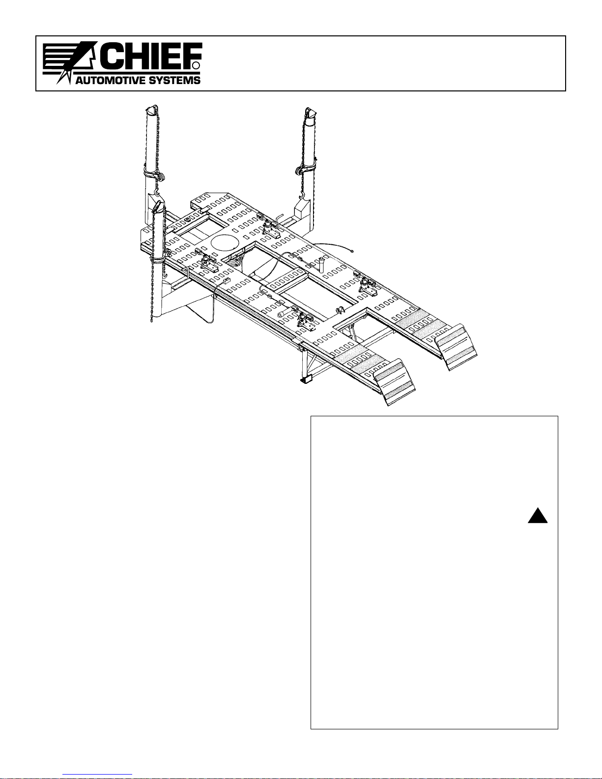
CHIEF EZ Liner S21M User manual

OWNERS MANUAL
ChiefEZLiner
S21M
R
2002 © Chief Automotive Systems, Inc.
USERS MANUAL
A INDUSTRIES COMPANY

CHIEF'S LIMITED ONE-YEAR
WARRANTY & LIABILITY
Chief Automotive Systems, Inc. warrants for one year from date of instal-
lation and/or purchase any of its products which do not perform satisfactori-
ly due to defect caused by faulty material or workmanship. Chief’s obliga-
tion under this warranty is limited to the repair or replacement of products
which are defective and which have not been misused,carelessly handled, or
defaced by repair or repairs made or attempted by others.
CHIEF AUTOMOTIVE SYSTEMS, INC. DOES NOT ASSUME
RESPONSIBILITY FOR ANY DEATH, INJURY OR PROPERTY
DAMAGE RESULTING FROM THE OPERATOR’S NEGLIGENCE OR
MISUSE OF THIS PRODUCT OR ITS ATTACHMENTS. CHIEF
MAKES NO WRITTEN, EXPRESS OR IMPLIED WARRANTY WHAT-
SOEVER OF MERCHANTABILITY OR FITNESS FOR A PARTICU-
LAR PURPOSE OR OTHERWISE REGARDING THE EQUIPMENT
OR ANY PART OF THE PRODUCT OTHER THAN THE LIMITED
ONE-YEAR WARRANTY STATED ABOVE.
Returned merchandise requires a “RETURNED GOODS AUTHORIZA-
TION NUMBER”on the package. Authorization numbers can be obtained
by calling or writing the Customer Service Department, Chief Automotive
Systems, Inc. No returned merchandise will be accepted without an autho-
rization number. All returned merchandise must be shipped freight prepaid
(and may be subject to a 15 percent handling and restocking charge) to:
Chief Automotive Systems, Inc.
Attn: Returned Goods Dept. Your Authorized
1924 E. Fourth St. or Chief Automotive Systems, Inc.
P.O. Box 1368 Representative
Grand Island, NE 68802-1368
R
CHIEF EZ LINER S21M
USERS MANUAL

R
CHIEF EZ LINER S21M
USERS MANUAL
This owners manual is written to familiarize opera-
tors with the safe and efficient operation of the Chief
EZ Liner S21M System. The S21M machine features
a unique multiple/simultaneous pulling method to
return the vehicle’s damaged structure and sheet
metal to its original position.
The S21M feature three towers at the front, with the
capability of adding one or two optional towers at the
rear providing 360 degree access to the vehicle. The
machine tilts hydraulically for either drive on or
winch positioning of the vehicle.
The S21M is Chief’s new “millennium”edition. Like
the S21 system,each tower features a 10 ton hydraulic
cylinder with a 10 inch stroke. The cylinders in the
S21M system; however, feature a larger diameter pis-
ton.
NOTE: Illustrations shown in this manual may vary
slightly from actual product.
This manual is not intended to replace Chief
Automotive Training. For information concerning
Training, contact Chief Automotive Systems, Inc.
1
IMPORTANT:
1. DO NOT attempt to operate the Chief EZ Liner
S21M without first reading this entire manual.
2. Complete safety information is highlighted
throughout this manual and is identified by:
This safety alert symbol identifies safety
information. Operator injury could result if these
CAUTION notes are not followed.
3. Qualified service personnel must check opera-
tional capacity of EZ Liner system prior to its ini-
tial use and at intervals of no more than one year.
Contact Chief Automotive Systems, Inc. or contact
your authorized Chief Automotive Systems, Inc.
representative.
4. Persons operating EZ Liner repair system must be
at least 18 years of age, must be trained in opera-
tion of EZ Liner system, and must have demon-
strated their qualifications to the employer. They
must also be specifically assigned to operate the
EZ Liner system by the employer and this assign-
ment must be made in writing.
!
CHIEF EZ LINER
S21M

R
CHIEF EZ LINER S21M
USERS MANUAL
HYDRAULIC SYSTEM COMPONENTS
The EZ Liner S21M is powered by an electrically oper-
ated hydraulic pump which is operated by a remote
control switch.The components of the system are iden-
tified in Figures 1a, and 1b.
Hydraulic pressure is distributed to tower rams, aux-
iliary rams, and lift ram. The flow of hydraulic fluid to
these rams is controlled by a valve. Hydraulic pres-
sure is monitored by pressure gauges mounted on the
machine’s front towers. To exert hydraulic pressure,
press ‘up’button on hand-held switch and to release
hydraulic pressure, press ‘down’button.
2
1. Pedestal
2. Removable Loading Ramps
3. Motor Starting Relay
4. Power Cord
5. Joy Cord
6. Square D Switch
7. Control Switch Assembly
8. Reservoir
9. Motor
Figure 1a
S21M Pump
10. Tower Valve (S21M)
11. Tower Ram
12. Auxiliary Ram Line Valve
13. Lift Ram Valve
14. Lift Ram
15. Pressure Gauge
16. Auxiliary Ram/Quick Coupler
Assembly
Basic Components
7
4
9
8
15
Figure 1b
12
1
11
3
NOTE: By holding
switch with Control
Cord down, stress
is reduced in this
area of cord.
IMPORTANT: Tower rams and auxiliary rams can
be operated either simultaneously (with equal
hydraulic pressure) or individually. The lift ram
must be operated individually. Whenever using
the hydraulic system, close all valves where
hydraulic pressure is not required.
NOTE: Although the S21M is a low pressure
system, it builds hydraulic pressure quickly. Be
aware of this quick reaction when making pulls or
lifting vehicle.
10
Down
Button
Up Button
16
14
2
13
6
5

R
CHIEF EZ LINER S21M
USERS MANUAL
Figure 2
Figure 3
To operate hydraulic system:
1.
Open valves to the hydraulic ram(s) to be used. Close
valves to all other hydraulic rams. (See Figures 2-4.)
NOTE: To open, turn valve 1/2 turn to left (counter-
clockwise). To close, turn valve to right (clockwise).
DO NOT overtighten. Over-tightening can damage
valve’s needle and seat.
IMPORTANT: When using lift valve, observe
caution label on lift valve cover.
2. Press up button on remote control switch to exert
hydraulic pressure and press down button to
release hydraulic pressure. (See Figure 1 —Page 2.
)
NOTE: Hold remote control switch so its cord is in
a downward position. This positioning
reduces stress in this area of the cord.
3. Monitor pressure gauge whenever exerting
hydraulic pressure. S21M readings represent tons
or kilo Newtons (kN).
NOTE:
1) Pressure gauge readings represent amount of
pressure each ram applies to its respective chain
(and vehicle). Each ram in use exerts the same
amount of pressure. The S21M pressure gauge
displays pressure readings intons or kilo Newtons
(kN).
2) Although the S21M is a low pressure system, it
builds hydraulic pressure quickly. Be aware of
this quick reaction when making pulls or lift-
ing the vehicle.
IMPORTANT:
Monitor pressure gauge continually
during repair. Even though the S21M is capable of
making strong pulls, most repairs can be made at
low pressure by using multiple pulls and proper
stress relieving of work hardened (folded)
metal.
Suggested low pressure for the S21M is one ton
(9 kilo Newtons).
3
CAUTION
Do NOT OpenThisValve Unless:
1.ALL TOWERS ARE PROPERLY PINNEDTOTHE
MACHINE.
2.VEHICLE’S WHEELS ARE BLOCKED, AND
EMERGENCY BRAKE IS SET.
!
Figure 4
S21M Lift Valve
(Side View)
S21M
Tower
Valve
(side view)
S21M
Auxiliary
Ram Line
Valve
Pressure Gauge

R
CHIEF EZ LINER S21M
USERS MANUAL
MOVABLE CROSSMEMBERS
The EZ Liner system features two movable crossmem-
bers that mount to the channels on the inner edges of
the mainframe. They can be used in front, center or
rear sections of machine. Illustration on Page 1 shows
normal location of crossmembers.
The primary use of movable crossmembers is to sup-
port and secure towers at ends of machine. They can
also be used as a base for making hydraulic pulls or
pushes when auxiliary rams are positioned perpendic-
ular (90 degrees) with top or bottom of crossmember.
To remove crossmember from machine, hold cross-
member secure while turning it counterclockwise. (See
Figure 5.) To reinstall crossmember, reverse the proce-
dure making sure it engages the channels on the inner
edges of the mainframe.
When movable crossmembers are used in front or rear
sections of machine, crossmember locks (see Figure 8)
must be used to prevent unintentional movement.
NOTE: EZ Liner S21M crossmembers do not feature
safety crossmember locks. These are available
on EZ Liner 25 systems only.
CAUTION:
1. Do not use movable crossmembers as a step.
2. Do not use movable crossmembers as a base to
make a hydraulic pull or push unless auxiliary ram
is positioned perpendicular (90 degrees) with top or
bottom of crossmember.
3. During removal and installation:
a. Hold crossmember secure.
b. Install crossmember locks to prevent uninten-
tional movement. Crossmember locks are not
designed to secure crossmember as a base for
hydraulic pulling/pushing.
Figure 5
4
!
Figure 6
Movable Crossmember Locks

R
CHIEF EZ LINER S21M
USERS MANUAL
TOWERS
The EZ Liner System is equipped with pulling towers
at front of machine. Optional rear towers are also
available. Multiple pulls can be set up quickly and are
controlled by a hand-held remote control switch.
Lateral and elevated pulling angles can be made or
changed in just a fraction of a minute.
CAUTION:
1. The 1/2 inch (13mm) tower chain is proof test-
ed to 28,000 lbs. and has a normal working
load limit of 13,000 lbs.
2. The 3/8 inch (10mm) tie down chain is proof
tested to 20,000 lbs.and has a normal working
load limit of 7,300 lbs.
IMPORTANT: The following information on towers
relates to front towers only! Although much of
this information is applicable to rear towers,
refer to Auxiliary Tower Owners Manual for
specific instructions.
To operate front towers:
NOTE: Tower operation requires use of tower pins or
tower tie bolts. The following procedure refer-
ences use of tower pins.Tower tie bolt applica-
tions appear on Page 7.
1. Swing tower to desired lateral pulling angle and pin
it to mainframe or movable crossmember. (See
Figure 7.) Tower pin can be used in any tie down
hole or along edge of machine. (See Figure 8.) DO
NOT position tower pin in front of or at rear of mov-
able crossmember as it will apply excessive stress
to crossmember locks. Instead, install tower pin
through crossmember tie down hole. (See Figure 7.)
Tower pin must be fully seated in lower pinning
hole to avoid damage to top pinning hole. (See
Figure 9.)
2.
To adjust slack tower chain, grip chain on each side
of tower. (See Figure 10.) Lift out on tail of chain
until it is approximately 45 degrees from tower.
Then disengage chain from tower head and pull
chain to either increase or decrease amount of slack.
5
Tower Pin
Tower Pin
Pinning Plate
Pin must be seated in
this Lower Pinning
Hole.
Figure 9
Figure 10
Pull in this direction.
Grip chain here
with opposite hand.
45°
Grip chain
here with
one hand.
!
Figure 7
Figure 8

R
CHIEF EZ LINER S21M
USERS MANUAL
3. Support collar with one hand while loosening collar
locking knob with opposite hand. Then position col-
lar approximately 3 inches (75 mm) above desired
pulling height and retighten collar locking knob.
(See Figure 11.)
NOTE: Make sure there is enough slack chain
before loosening collar.After loosening lock-
ing knob, it might be necessary to turn col-
lar slightly to disengage it from tower pipe.
4. Let tower chain hang free momentarily to remove
twist. Then, without twisting chain, attach hook to
vehicle.Pull on tail end of chain to remove slack and
then lower collar. (See Figure 12.)
IMPORTANT: Remove twist from chain before
lowering collar. Make sure that
chain links between collar roller
and hook align.
5. Open tower valve. Then press up button to exert
pressure and down button to release pressure.
CAUTION: Observe following WARNING label
which appears on tower.
IMPORTANT: DO NOT tighten collar locking
knob while pressure is applied to
system because it will be impos-
sible to loosen the knob without
pressure on the system. If it has
been tightened by error while
pressure is on the system, reap-
ply pressure and loosen the
knob.
6. When tower is no longer needed, close tower valve,
disengage tower chain hook, and store collar using
one of the three methods shown in Figure 13.
CAUTION:
1. Collar locking knob must be tightened before
removing tower chain from vehicle.
2. Collar locking knob must be tight when collar
is not in use.
3. Store collar at bottom of tower pipe or support
collar with tower chain.
Figure 11
Figure 12
6
Tower chain will be
attached to vehicle here.
3" (75mm)
Collar Locking Knob can be left
loose while pull is being made;
however, it must be tightened
before removing Chain from
vehicle.
Hook attached to vehicle.
Desired pulling angle. (Slack chain is
removed.)
Collar Locking Knob
(When Collar and Chain
are stored this way,
Collar Locking Knob
must be tightened
before removing Tower
Chain from vehicle.)
Collar is
supported
by Tower
Chain.
Collar is resting
on Tower Gusset.
!
!
Figure 13
WARNING!
DO NOT position yourself close to, or in line
with, chains, clamps, or other accessories while
pressure is applied to this system. Failure to
observe this warning could result in operator
injury due to the possibility of a chain or acces-
sory disengaging or failing while pressure is
applied to this system.

R
CHIEF EZ LINER S21M
USERS MANUAL
TOWER TIE BOLT APPLICATIONS
Certain pulling and/or pushing situations necessitate
use of tower tie bolts in place of tower pins. Tower tie
bolts must be inserted through one of the outer tie
down holes on mainframe (or movable crossmembers)
and be threaded into one of the pinning holes on tower
gusset. Tower tie bolts must be tightened to between
120-150 foot pounds (160 -200 Nm) of torque.
Tower tie bolts must be installed when the following
situations exist:
1. Tower does not lift up firmly against underside of
mainframe when making a pull, for example: when
pulling upward at 45 degree angle or less. (See
Figure 14.)
NOTE: Tower will not lift in this situation and will
be forced down if tower tie bolt is not
installed.
2. Auxiliary ram is used to push from tower to vehicle.
(See Figure 15.) Tower will be forced down in this
situation unless tower tie bolt is installed.
CAUTION: DO NOT attempt this setup with-
out reading Auxiliary Ram Owners
Manual.
3. Pull from side of tower exceeds 45 degree angle from
tower base. (See Figure 16.) This situation does not
necessarily force tower up or down, but instead
causes tower pedestal rings to twist.
NOTE: The higher collar is on tower, the more
severe the twisting action.
Figure 14
Figure 15
!
NOTE: Tower will not lift in
this case and would
be forced down if
Tower Tie Bolt was
not installed.
Tower Chain will be attached
to vehicle here.
Tower Tie Bolt installed.
45°
Use additional attachment here to
protect Extension Tubing while
pushing on vehicle.
1 —6" (150mm)
Auxiliary Ram
2 —“V”Base
1
2
Tighten Tower Tie Bolt to
specified torque. When Tower Chain is used in this
area, Tower Tie Bolt is not required. It
is required beyond this point.
Tower Chain Hook is
attached to vehicle here.
Tower Tie
Bolt
7

R
CHIEF EZ LINER S21M
USERS MANUAL
LOWERING/RAISING MACHINE
When lowering or raising a machine with a vehicle
aboard observe the following precautions.
CAUTION:
1. When driving or winching vehicle on or off machine,
use helper to guide you. If vehicle's brakes are inop-
erable, use a Chief Winch and refer to instructions
packaged with that accessory.
2. Immediately after positioning vehicle on main-
frame, put vehicle in park (if automatic transmis-
sion), apply vehicles emergency brake, and have
helper block vehicles wheels.
3. Prior to lowering machine, slowly roll vehicle to rear of
machine,put vehicle in park (if automatic transmission),
apply vehicles emergency brake, and block vehicles
wheels.Then install loading ramps at rear of machine.
4. Keep vehicles wheels blocked during raising and
lowering procedures and whenever vehicle is not
anchored to mainframe.
5. When raising or lowering machine with vehicle
aboard, DO NOT walk behind machine.
TO LOWER MACHINE
IMPORTANT: Observe preceding precautions when
lowering machine with vehicle
aboard.
1. Position towers at front of machine and secure them
to front movable crossmember using tower pins.
NOTE: If EZ Liner is equipped with auxiliary tow-
ers, bolt these towers to sides of machine
using outermost tie down holes in fifth row
of tie down holes from rear of machine.(See
Auxiliary Tower Owners Manual.)
2. Install loading ramps at rear of machine.
3. Raise lift valve cover and open lift valve half turn to
left. Then close all other ram valves.
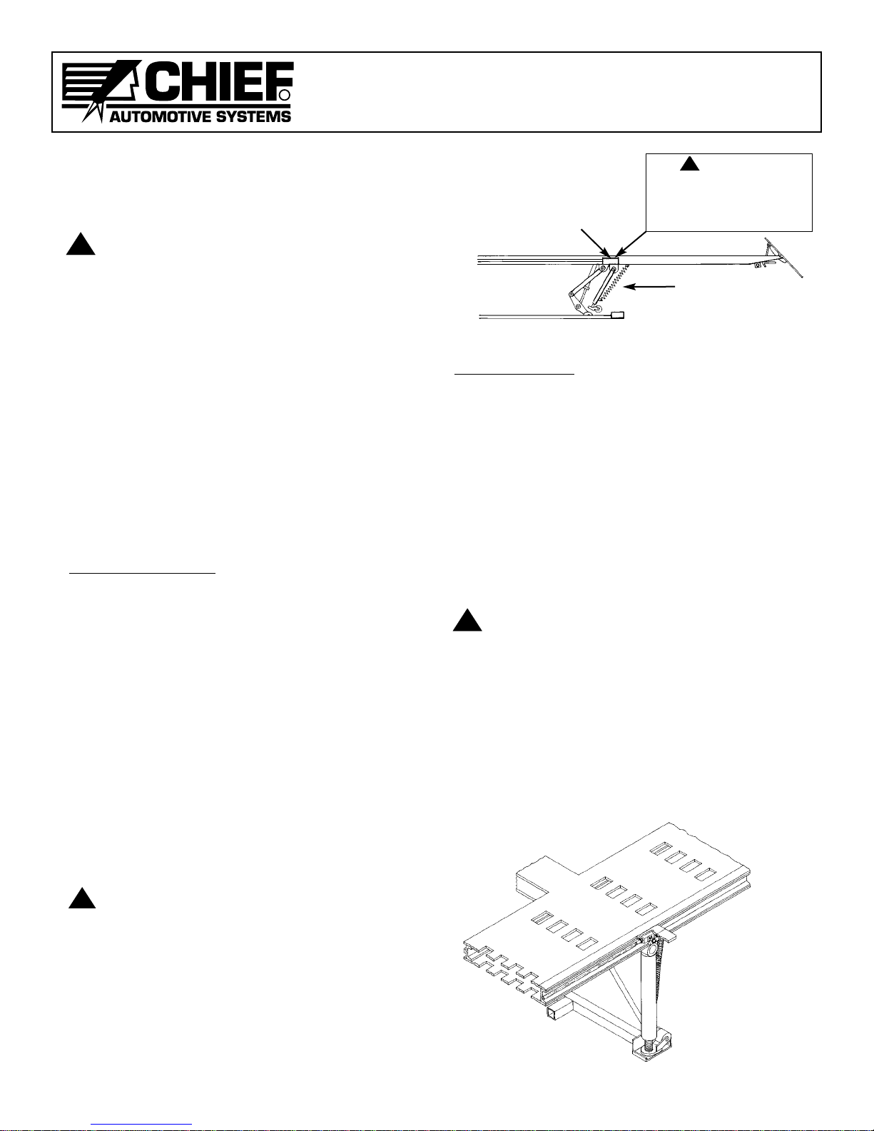
4. Press 'up' button on remote control switch to lift
machine until there is no weight on stiff legs. Then
swing stiff legs forward until they are at 30 degree
angle from their vertical position. (See Figure 17.)
CAUTION:
1. Clear all obstacles from under and around
machine.
2. DO NOT allow anyone or anything to ride on
machine or be under machine during lowering
procedures.
5. Press 'down' button on remote control switch to
lower rear of machine to floor.
NOTE: DO NOT lay remote control switch on machine.
Figure 17
To Raise Machine
IMPORTANT: Observe preceding precautions when
raising machine with vehicle aboard.
1. Check location of towers making sure they are
secured to machine as noted in Step 1 —To Lower
Machine.
2. Raise lift valve cover and open lift valve half turn to
left. Then close all other ram valves.
3. Press ‘up’button on remote control switch to lift
machine until stiff legs are in upright position.Then
press ‘down’button to lower stiff legs into their
respective stiff leg catch. (See Figure 18.)
CAUTION:
1. Clear all obstacles from under and around
machine.
2. DO NOT allow anyone or anything to ride on
machine or be under machine during raising pro-
cedures.
NOTE: When mainframe lifts off floor, safety
ramps automatically pivot into position.
4. Close lift valve and lower lift valve cover.
IMPORTANT: Lift valve must be closed when
using auxiliary towers and rams.
Figure 18
8
!
!
Open Lift Valve and raise machine until
there is no weight on its Stiff Legs.
Swing Stiff Legs forward until
they are at 30 degree angle
from their upright position.
!
Stiff Leg is in position and
resting within Stiff Leg
Catch.
CAUTION
Do NOT OpenThisValve Unless:
1. ALLTOWERS ARE PROPERLY PINNED TO
THE MACHINE.
2.VEHICLE’SWHEELS ARE BLOCKED, AND
EMERGENCY BRAKE IS SET.
!

R
CHIEF EZ LINER S21M
USERS MANUAL
MACHINE MAINTENANCE
Check And Inspect
These components should be checked 'monthly' and
anytime a problem is suspected.
Tower Chains,Tie-Down Chains
The tower chains/hooks and tie down chains/hooks
supplied with the EZ Liner S21M are high quality,
high strength chains/hooks. If replacement is
required, purchase only the original Chief product
from an authorized Chief Automotive Systems, Inc.
representative.
CAUTION:
1. DO NOT heat chain or hook while repairing vehicle
—600F (316C) of heat on chain will weaken it.
2. DO NOT tip load chain hook.Tip loading chain hook
will stress hook beyond its designed capability and
could cause hook to fail.
3.
DO NOT pull with twisted chain links. Pulling with
twisted chain links will stress chain links beyond
their designed capability and could cause chain to fail.
Tower chains must be inspected for wear, nicks,
gouges, stretched and bent links. If found, replace
chain.
Tower chain hooks must be inspected for twist and
stretched openings. If found, replace chain.
Safety Ramp
Inspect safety ramps making sure they lift into posi-
tion each time the machine is raised. Lubricate hinges
and other moving parts with oil if they do not lift into
position.
Pedestal Bolts
Remove pump lid and check mainframe to pedestal
bolts/ nuts for looseness.
Power and Control Cords
Inspect power and control cords for worn insulation or
other damage. If found, replace cord(s).
Tower To Mainframe Gap
Measure gap between top of tower gusset and bottom
of mainframe. If gap measures between 5/16 inch
(8mm) and 7/16 inch (11mm), see Tower Tie Bolt
Usage, Page 7. If gap exceeds 7/16 inch (11mm), see
Troubleshooting Section —Tower To Mainframe Gap,
Page 16.
Cleaning and Lubricating
These components should be cleaned and lubricated as
specified for trouble free and extended service. When
lubricating use the following:
Oil —Use motor oil for all components requiring oil.
Grease —Use a SUS750 Lithium type grease such as
lubricate #630-2 for all components requir-
ing grease.
Tower Heads
Grease tower heads every six months.
1. Remove tower chain from tower head.
2. Remove tower head from tower pipe.
3. Clean dirt from tower head rub pads and where
tower head pipe rubs on inside of tower pipe.
4. Apply grease to tower head pipe and rub pads.
5. Reinstall tower head and tower chain.
Collars
Clean and lubricate collars monthly.
1. Use compressed air to blow out dirt or dust that col-
lects between collar ears and rollers.
CAUTION: Wear safety glasses while using com-
pressed air to blow out dirt and dust.
2. Place a few drops of oil on roller pin between roller
and collar ears (each side). Then turn roller a few
times. Roller must turn freely.
Lift Jack
Grease lift jack every six months.
1. Clean dirt and excess grease from lift jack's pivot
points.
2. Using grease gun, apply grease to grease fittings of
each lift jack pivot point.
9
!
!

R
CHIEF EZ LINER S21M
USERS MANUAL
Stiff Leg Assembly
Oil stiff leg assembly pivot points and rollers every
two months.
1. Clean dirt from pivot points.
2. Place a few drops of oil at each pivot point and on
roller pins.
Tower Rings
Grease tower rings every six months. Dirt and plastic
dust can accumulate on rings and pedestal ring groves
causing towers to turn hard. Developing a bead of
grease between rings and pedestal ring grooves seals
out much of the dirt and plastic dust.
1. Wipe old grease and dirt from rings and pedestal
ring grooves.
2. Swing towers to one side of machine and position
against mainframe.
3. Use grease gun to apply grease to each grease fit-
ting (2 per ring) on rear half of each ring. Apply
enough grease so a small bead of grease develops
between ring and pedestal ring groove.
4. Swing towers to opposite side of machine and posi-
tion against mainframe. Then repeat Step 3.
5. Swing towers several times to work grease around
rings and pedestal ring grooves. If more grease is
needed, repeat the procedure.
NOTE: If tower still swings hard, see
Troubleshooting Section —Towers Swing
Hard, Page 16; or, see following segment on
Cleaning Pedestal Ring Grooves.
Cleaning Pedestal Ring Grooves
If preceding procedures will not correct tower(s) that
swing hard, thoroughly clean pedestal ring grooves.
1. Swing towers to one side of machine and bolt towers
to mainframe using tower tie bolts.
CAUTION: Failure to properly bolt towers to
mainframe could result in operator
injury as well as damage machine.
2. Remove upper and lower rear halves of tower ring.
IMPORTANT: Mark each ring's location before
removing and note number and
location of shims that are between
front and rear halves of rings.
Rings and shims must be rein-
stalled in their original locations.
3. Wipe dirt and grease from rings and pedestal ring
grooves. Then wipe ring grooves with a solvent
soaked rag and wipe dry.
4. Apply grease to pedestal ring grooves.
5. Replace upper rear halves of rings and secure bolts
—snug only.
6. Remove tower tie bolts, swing towers to opposite
side of machine and reinstall tower tie bolts secur-
ing towers to mainframe.
CAUTION: Failure to properly bolt towers to
mainframe could result in operator
injury as well as damage to machine.
7. Remove upper rear halves of rings and repeat Step
3 on this side of machine.
8. Apply grease to pedestal ring grooves and to rear
halves of rings.
9. Replace upper and lower rear halves of tower rings
and tighten ring bolts.
IMPORTANT: Rings and shims must be rein-
stalled in their original position.
10. Apply a small bead of grease between rings and
pedestal ring grooves to keep much of the dirt and
plastic dust out of the ring area. See preceding
information on Tower Rings.
Eliminating Air In Hydraulic System
All air has been removed from hydraulic system at the
factory, but if hydraulic system is opened to replace a
system component, it is necessary to bleed air from
system prior to using it.
Bleeding Air In System At Quick Coupler
1. Separate quick coupler.
2. Place male end of quick coupler in container and
hold rag over container and quick coupler.
CAUTION: Wear safety glasses to protect eyes
from hydraulic oil in the event it squirts out
of container and past the rag.
3. Depress ball check at end of quick coupler against
bottom of container.
CAUTION: DO NOT have any pressure on the
system when pressing ball check on quick
coupler.
4. Press up button on control switch to pump air out of
system and continue until only hydraulic oil is being
pumped out.
5. Reconnect quick coupler.
6. Refill hydraulic fluid reservoir to within 1" (25mm)
of top with SUS215 viscosity 100 degrees F (38 C)
10W hydraulic oil or automatic transmission oil
with all other rams or towers fully retracted.
Bleeding Air From System Beyond Quick Coupler
Contact an authorized Chief Automotive Systems, Inc.
Service representative.
10
!
!
!
!

R
CHIEF EZ LINER S21M
USERS MANUAL
Pump Removal
1. Disconnect power supply cord from power supply
and pull cord out through top of pedestal opening.
2. Coil remote control switch cord and position it on
top of motor.
or
Disconnect remote control switch cord from motor
and pull it out through bottom of pedestal.
3. Lift pump out of pedestal.
NOTE: If bolts securing pump to base of pedestal
have not previously been removed, remove
them. The bolts are only necessary for
transporting the EZ Liner.
Pump Installation
1. Set pump into pedestal.
NOTE: It may be necessary to pull up slightly on
hose that attaches pump to hose block to
prevent it from being pinched under pump.
2. If remote control switch cord is coiled and posi-
tioned on top of motor, route
hand-held control unit
out through bottom of pedestal.
If remote control switch cord is disconnected,
reroute cord at top of pedestal through to bottom of
pedestal and reconnect it to motor.
3. Insert power supply cord at top of pedestal, route it
through to bottom of pedestal, and plug it into
power supply.
IMPORTANT: Following installation, check posi-
tion of all hydraulic andelectrical
lines to be sure they are not pinch-
ed under pump.
11
HYDRAULIC PUMP REMOVAL/INSTALLATION

R
CHIEF EZ LINER S21M
USERS MANUAL
TROUBLESHOOTING
PROBLEM CAUSE POSSIBLE SOLUTION
Pump Will Not:
12
Run
Build pressure or
builds pressure slowly.
Hold pressure
Operate efficiently
under pressure
Ram Will:
Jump
Not Extend
Not Retract
Hydraulic Oil Leakage:
Bad square D switch.
Bad motor starting relay.
Power cord disconnected.
Poor electrical connector.
No power to motor.
Circuit breaker tripped or blown fuse.
Broken wires in control cord.
Bad motor.
Bad power cord and/or switch.
Hydraulic fluid is low.
Bad pin and piston kit or bad low
pressure spring.
Quick Coupler at shut off valve is
loose.
Release valve open all the time.
Contamination in valve.
Valve bleeding pressure.
Hydraulic oil leak.
Faulty check valves.
Extension cord is too long or wire
gauge is too small.
IMPORTANT: Extension cord
usage is not recommended. If
used, extension cords must
meet standards (listed at right)
and be used on a short term
basis only.
Facility wiring is inadequate.
Air in hydraulic system.
Valve not open.
Loose quick coupler.
Pump will not build pressure.
Loose quick coupler.
Dirt in quick coupler.
Ram piston is bent.
Hose leaking.
Loose quick coupler.
Loose fitting.
Inadequate sealant in pipe
threads.
Overfilled pump reservoir.
Replace square D switch. Contact Chief Automotive
Systems Service Representative.
Replace motor starting relay. Contact Chief
Automotive Systems Service Representative.
Plug in power cord.
Replace plug or receptacle.
Check circuit.
Reset circuit breaker or replace fuse.
Replace control cord or repair it.
Replace motor/pump assembly.
Replace power cord and/or switch.
Fill fluid reservoir to within 1" (25mm) of top with
SUS215 Viscosity @ 100°F (38C) 10W hydraulic
oil or automatic transmission oil with all rams
down and machine sitting level.
Replace pin and piston kit or low pressure spring.
Contact Chief Automotive Service Representative.
Tighten Quick Coupler.
Contact Chief Automotive Service Representative.
Operate pump and release pressure several times
to flush valve.
Flush valve or replace.
Check hoses, fittings, and quick couplers, and tight-
en or replace.
Replace internal check valves. Contact Chief
Automotive Service Representative.
Use extension cord rated for 25 amps at 120 volts
with ground wire up to 25 feet (7.5m) long, or
use extension cord rated for 16 amps at 220
volts with ground wire up to 25 feet (7.5m) long.
Rewire facility to comply with local electric code.
Add dedicated line with 30 amp breaker.
Bleed air from system. See Machine Maintenance,
Page 10.
Open valve one turn.
Tighten quick coupler.
See Pump Problems above.
Tighten quick coupler.
Disconnect quick coupler and clean male and
female halves.
Replace ram.
Replace hose.
Tighten.
Tighten.
Apply teflon tape to pipe threads after properly
cleaning and retighten.
Drain oil to 2" (50mm) below fill cap.

PROBLEM CAUSE POSSIBLE SOLUTION
Machine Will Not:
Lift Lift valve not open. Open lift valve one turn.
Loose quick coupler on lift ram. Tighten.
Other valves open. Close all other valves.
Too much weight at rear of machine. Move vehicle forward on machine.
Vehicle weight exceeds 6,500 lbs. Do not attempt to load vehicle.
(2925 kg.) capacity.
Inadequate hydraulic pressure. Check pressure gauge to see if 2.5 ton
of hydraulic pressure is being used, and
increase pressure if it is not.
Object under pedestal. Lower machine and remove object.
Lower Lift valve not open. Open lift valve one turn.
Loose quick coupler on lift ram. Tighten.
Restrictor valve spring has lost some of Remove restrictor valve spring located
its strength. in block next to lift valve, and stretch it
slightly. Reinsert spring and try again.
CAUTION: Machine must be sup-
ported by machine’s stiff
legs before removing
restrictor valve spring.
Object under lift mechanism. Raise machine and remove object.
Dirt in restrictor swivel orifice. Disassemble and clean.
Swing Hard Ring grooves are dirty. Clean and regrease. See Machine
Maintenance, Page 9.
Bent tower rings. Repair or replace. Contact Chief
Automotive Service Representative.
Crushed ring bearings. Replace bearings. Contact Chief
Automotive Service Representative.
To Mainframe Gap Exceeds 7/16 inch Improper use. Readjust tower. Straighten tower ring.
Contact Chief Automotive Service
Representative.
Jump When Swung Pedestal is dented. Repair or replace pedestal. Contact Chief
Automotive Service Representative.
!
Towers:
Collars Jump:
Under Load Improper fit between collar and Refit collar. Contact Chief Automotive
tower pipe. Service Representative.
When Pressure Is Released Defective surge valve. Replace surge valve. Contact Chief
Automotive Service Representative.
Improper fit between collar and tower Refit collar. Contact Chief Automotive
pipe. Service Representative.
FOR ADDITIONAL TROUBLESHOOTING INFORMATION OR A SERVICE ENGINEER, CONTACT CHIEF AUTOMOTIVE
SYSTEMS, INC., 1-800-445-9262 (TOLL FREE).
(11mm)
R
CHIEF EZ LINER S21M
USERS MANUAL
13
Machine Will Not:

Weight (30 Series)......7,000 lbs. (3,175 k.g.)
Weight (31 Series)......7,588 lbs. (3,442 k.g.)
Weight (32 Series)......8,033 lbs. (3,644 k.g.)
Power Required..........120v, 15 amp, 60 hz.
Hydraulic Power..........10 tons per tower (89 kN)
Hydraulic Fluid............9.5L SUS215 Viscosity, 100°F (38C), 10W
Controls.......................One hand-held unit on 21’(6.4m) of cord
Length.........................21’8”(6.6m) (safety ramps included)
23’1”(7m) maximum length with front
towers extended
24’3”(7.39m) with front and rear towers
extended
Width...........................7’4”(2.23m)
12’10”(3.9m) with front towers extend-
ed to both sides
14’4”(4.4m) with front and rear towers
extended to both sides
Height..........................8’5”(2.56m)
9’3”(2.82m) with tower rams extended up
Clearance...................2’(.6m) recommended on all sides
Working Height...........31”(.79m) from floor to top of mainframe
Tie Down Openings....250
Lift Capacity................6,500 lbs. (2,950 k.g.)
Sound Pressure
Level at Control
Position.......................81 dB(A)
EZ Liner S21M Specifications
CHIEF EZ LINER S21M
USERS MANUAL
14
R

R
P.O. Box 1368
Grand Island, Nebraska 68802-1368
Phone: 308/384-9747
Fax: 308/384-8966
INTAIRCO S.A.R.L.
CA de TREMBLAY CHARLES DE GAULLE
18, rue Henri FARMAN
93297 TREMBLAY EN FRANCE CEDEX
TEL 01 41 51 16 80
FAX 01 48 60 09 88
www.chiefautomotive.com
Chief reserves the right to alter product specifications
and/or package components without notice.
Form EZL S21M UM (Rev. 1/02)
Part No. 601198 2002 © Chief Automotive Systems, Inc.
Table of contents
Other CHIEF Power Tools manuals
Popular Power Tools manuals by other brands

Hilti
Hilti WSJ 750 Original operating instructions

Ammann
Ammann ADS 70 Translation of the original operating instructions

Hitachi Koki
Hitachi Koki H 60MA Handling instructions

molex
molex 63823-3900 Specification sheet

Roller
Roller Akku-Picco P 40 operating instructions

AEG
AEG WS 2200-180 Original instructions

Greencut
Greencut EBW700 instruction manual

haupa
haupa AS-6 instruction manual

Star Tec PRODUCTS
Star Tec PRODUCTS ST 902 operating manual

Milescraft
Milescraft Plunger 1000 quick start guide

HIKOKI
HIKOKI RH 18DA Handing instructions

TYROLIT Hydrostress
TYROLIT Hydrostress DME24MW Series operating instructions