manuals.online logo
Brands
  1. Home
  2. •
  3. Brands
  4. •
  5. Laskomex
  6. •
  7. Intercom System
  8. •
  9. Laskomex CD-2000 Installation manual

Laskomex CD-2000 Installation manual

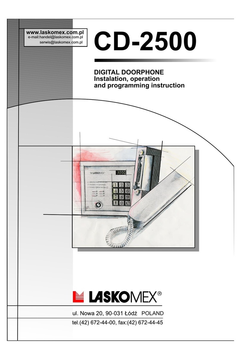
CD-2500
DIGITAL DOORPHONE
Instalation, operation
and programming instruction
www.laskomex.com.pl
e-mail:[email protected]
[email protected]
POLAND
All manuals and user guides at all-guides.com
- 1 -
CD- Elementy systemu domofonowego2500
FEATURES OF ENTRYPHONE SYSTEM CD-2500
For the installer
1.Two-wire installation. All the uniphones are connected to the electronics cassette
through the agency of a two-wire bus
2. The possibility of connecting up to 254 subscribers to one standard electronics
cassette
3. Small dimensions of the conversations cassette, providing for simultaneous
selection of flat numbers within the range of 1-999
4. Servicing and installation procedures which make for easy installation and possible
repairs of the interphone system.
5. The possibility of controlling the electro-catch or the electromagnetic lock.
For the investor
1. Illuminated keyboard without mechanical contacts.
2. High resistance to mechanical damages. The conversations cassette in the CD-
2500 system has been additionally reinforced in order to minimize the risk of
destruction of the equipment in result of vandalism.
3. Protection from noxious influence of atmospheric conditions.
4. Low cost of the equipment calculated per one resident. The possibility of servicing
254 residents, simple installation of the equipment and small dimensions of the
conversational cassette are decisive for low price of the equipment in case of
installation in buildings with big number of residents.
5. The possibility of construction of multi-output systems with separated main input
(e.g. leading onto the premises) and secondary inputs. This solution entails the
application of special electronics cassettes.
6. Electronic key with a Dallas pellet. Real estate administrators and their subordinate
services can use one key for entry into all the facilities under their supervision. The
key is equipped with a unique number which is very difficult to counterfeit; on the
basis of this number the key reader makes its identification.
For the user
1. Code lock function. Allows for entering the premises without the necessity of using
keys.
2. Key with a Dallas pellet. Small dimensions and weight, the possibility of application
in other equipment and systems and the difficulty in counterfeiting the key make it
an attractive alternative to traditional mechanical keys.
3. Lack of possibility of eavesdropping a conversation from other uniphones.
Conversation in the CD-2500 system cannot be performed with more than one
uniphone at a given moment.
All manuals and user guides at all-guides.com
- 2 -
CD- Elementy systemu domofonowego2500
LIST OF CONTENTS
1. Components of the CD-2500 System 3
2. Configuring the Interphones Operation 4
3 Operational mode of the entryphone system CD-2500 4
3. Installation. 4
3.1. Installation of control panel. 6
3.2. Connection of control panel with electronic cassette. 6
3.3. Programing the entryphone. 6
3.4. Connecting uniphones to electronic cassette. 7
3.5. Conecting system power supply. 7
3.6. Checking of voltages at test points. 8
3.7. Error and fault messages. 8
3.8. Adjustments. 9
3.9. Additional notes. 9
4.Programming. 10
4.1. Access to system procedures. 10
4.2.Description of installation programs. 11
5. Multi-entrance system. 16
6. Electronic key with a DALLAS pellet 19
7. Operation. 22
7.1. Control panel-to-uniphone call. 22
7.2. Coded lock. 23
7.3. Change of lock code. 23
8. Troubleshotting of the system. 24
8.1. Errors resulting from incorrect installation of the uniphone. 24
8.2. Call signal fails to operate. 24
8.3. Troubles with number input. 24
9. Technical specification 25
All manuals and user guides at all-guides.com
- 3 -
CD- Elementy systemu domofonowego2500
1. Components of the CD-2500 System
Conversational cassette CP:
CP-2500/SR - CP panel, color: silver
CP-2500/CZ - CP panel, color: black
CP-2500 TM - panel with Dallas key reader
Conversational cassettes in the CD-2500 system are universal devices utilized both
in the basic system (with one or multiple outputs) as well as in the output hierarchy
system. In the basic version they are designed for assembly under the stucco.
Conversational cassette casing
By standard, the conversational cassettes and the resident lists are supplied in
under-the-stucco frame, the casings allow for mounting these devices over the
stucco. An illuminated number panel is also available, which allows for the resident
list or the address of the premises to be placed.
4101 - over-the-stucco one-segment casing
4201 - over-the-stucco two-segment horizontal casing
4202 - over-the-stucco two-segment vertical casing
4301 - over-the-stucco three-segment horizontal casing
4303 - over-the-stucco three-segment vertical casing
NP4100 - illuminated number panel (resident list)
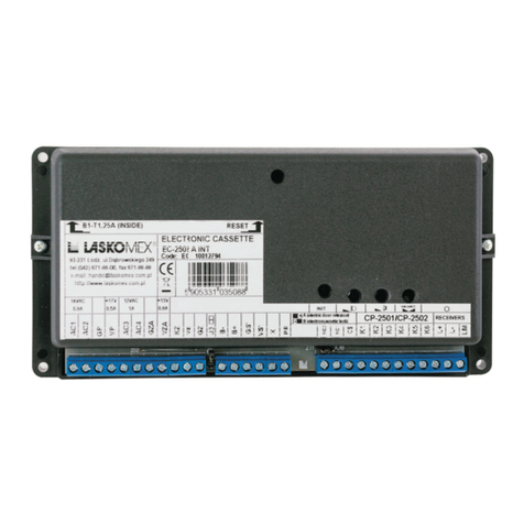
Electronics cassette EC-2500
EC-2200 - standard electronics cassette
EC-2200/H - primary electronics cassette for multi-entrance systems
EC-2200/U - secondary electronics cassette for multi-entrance systems
Uniphones
The CD-2500 requires the use of uniphones with digital decoder designed and
manufactured by the Laskomex company. One should not use digital uniphones
made by other manufacturers nor uniphones designed for multi-wire analog interphone
systems. The Laskomex company offers five models of uniphones designed for
digital interphone systems CD-2000, CD-2500, CD-3000: LF-8, LX-8, LT-8, LR-8,
LM-8,.
Feeder
TR 2300 - power supply transformer for CD-2500 exchange
Battery
it is possible to connect a battery to the electronics cassette. In case of using a
battery, one should solder in an R69 resistor (27 0hm/0.5W) on the electronics
cassette plate. This solution should be applied in case where short power supply
tension decays are projected. We recommend to use a battery of capacity not bigger
than 7 Ah.
All manuals and user guides at all-guides.com
- 4 -
CD- Elementy systemu domofonowego2500
Electrocatch or electromagnetic lock
The entryphone system allows for control of an entrance blocking device: an
electrocatch or an electromagnetic lock. The time of releasing the electrocatch or
electromagnetic lock is set up by program with the use of an appropriate procedure.
These devices are connected directly to the conversational cassette. It is recommended
to use 12V AC/DC electrocatches with current intake not exceeding 0.7A for alternate
current and 1A for direct current can be used.
Door opening button
The button is used at releasing the electrocatch or electromagnetic lock upon leaving
the facility. As a button, any short-circuit button, such as bell button or raid button
used in alarm systems.
Additional calling button
The module allows for additional (acoustic or optical) signaling of calling in the
uniphone. It is used in a situation when the uniphone is located in a compartment
with high noise level, or persons with hearing deficiency are in it. It allows for the
activation, for the time of the calling, of any equipment powered with 12...24V voltage
 a bell, a siren or a signaling lamp.
2. Configuring the Interphones Operation
Basic system.
In the basic system, the interphone consists of electronics cassette EC-2000,
conversational cassette CP-2500, power supply feeder and uniphones (up to 254).
It allows for establishing communication between the conversational cassette mounted
at the entrance and one of the 255 uniphones mounted in apartments. All the
functions of the CD-2500 entryphone are available.
Multi-entrance system with entrance hierarchy.
Multi-entrance system is used in case two entries lead to the given apartment or
group of apartments. It is also applied in separated housing estates with one common
entry secured by an entryphone, and independently protected entrances to buildings
or staircases. The construction of such system requires the application of a system
of electronic cassettes designed specifically for that purpose: EC-2000/H servicing
the conversational cassette at the main entrance and EC-2000/U servicing the
conversational cassette at the secondary entrance.
In the multi-entrance system, main entrance is highlighted (e.g. entrance to the
enclosed housing estate area), from which connection can be established with each
of the apartments, as well as subordinate entrances leading directly to an apartment
or a group of apartments (e.g. entrance to the staircase).
3 Operational mode of the entryphone system CD-2500
Normal mode
In normal mode, the uniphones physical number (programmed by jumpers) matches
the logical number (the one at which the uniphone responds after its number is
selected from the keyboard). This is the default operational mode.
Numbering with range transposition mode
The uniphones physical number (programmed by jumpers) does not match its logical
All manuals and user guides at all-guides.com
- 5 -
CD- Elementy systemu domofonowego2500
number (the one at which the uniphone responds after its number is selected from
the keyboard).
logical number = physical number + range transposition
Example:
In the facility, apartments with the following numbering shave to be serviced.
Minimum apartment number 310
Maximum apartment number 360
In apartment no. 310 (logical number) we use jumpers to set the physical number
value to 1, in apartment 311 to 2, etc. We set the value of range transposition to
309. Keyboard selection of a number within the range of 310-360 shall cause a
uniphone to ring in that apartment.
Hotel numbering mode
ground floor 001, 002, ... , 010
I floor 101, 102, ... , 110
II floor 201, 202, ... , 210
........................................................
IX-floor 901, 902, ... , 910
In order to attribute numbers fo appartaments to successive numbers wich are set
up in uniphones, is recomended to set up the electronics cassette into hotel numbering.
We use P-2-9-7 program for this purpose and parameter in this program should be
set as 0. Then we have to set range transposition to value wich corresponds to
amount of flats on the floor (there is 10 for example). P-9 program is used for setting
the range transposition and all programs are described in instruction of instalation,
using and programing. Calculation of number wich is set into uniphone in flat number
PXX with hotel numbering mode is calculated according to the following algorithm:
U=P*LL+XX
where:
U- uniphone number
P- floor number
LL- liczba lokali na piêtrze
XX- numer lokalu na piêtrze
For the given example, the numbers at which the uniphones at the apartments have
to be programmed are the following:
001-1 ,002-2, ... , 010-10
101-11 ,102-12,... , 110-20
......................................................
901-91 ,902-92,... , 910-100
All manuals and user guides at all-guides.com
- 6 -
CD- Elementy systemu domofonowego2500
3. Installation.
3.1. Installation of control panel.
The door phone system control panel is mounted either to a building wall or to a
fixed door leaf by means of four screws, using suitable openings in the control panel
rear wall. Large openings are designed for condutors connecting the control panel
with electronic module.
The control panel front plate should be placed in the panel rear part installed on
the wall and then it should be mounted by means of two M4 screws. To protect the
front plate against theft, use two tearable rivets, supplied with the system.
The second version makes possible to mount the front plate by means of screws
screwed from the rear side (mounting in fixed leaf of the door). The keypad uses
7 infrared beams (3 vertical and 4 horizontal) intersecting at places marked with
digits. Interception of appropriate beam pairs when a desired mark is touched
produces a selection signal for a processor controlling the system operation.
If possible, the control panel should be installed inside the house (vestibule,
windshield); outdoor installation should be avoided. Dirt on the control panel (snow,
mud) or flooding it with water may result in incorrect operation of the system until
the control panel is cleaned or dried. Electronic modules controlling operation of
the keypad and display are resistant to temperature variations within the range from
-30o C to +60o C and to normal atmospheric effects.
3.2. Connection of control panel with electronic cassette.
At least six-wire conductor is required to connect the control panel to the electronic
cassette. Special attention should be paid to proper connection of signals to
individual wires of the conductors. This will result in elimination of hum involved
with digital control of the display. Individual terminals are designed as K1 to K6.
The K1 terminal of the control panel is to be connected to the K1 terminal of the
electronic cassette etc.
When selecting the conductor wires for connection of signals, a rule should be
observed that the digital signal paths should be as distant from the analog signal
paths as possible; it is also desirable to have the digital and analog paths separated
by the analog common wire (K5).
Wires of the conductor supplying the electric catch (terminals R+ R-) need not be
screened. If a conductor with greater number of wires is used the non-used wires
are connected to terminal K5-K5. The conductors should be connected with the
power supply switched off.
NOTE:
Incidental connection of the terminals K1 and K2 with the power supply switched
on may result in unrepairable damage of the keypad.
3.3. Programing the uniphone.
Generally, each uniphone is programmed by the wireman with a number corresponding
to a number of a flat in which the uniphone is installed.
If the flat numbers are greater than 254 the uniphone is programmed by assignment
of a successive number in the system and the central unit should be prepared (by
means of suitable installation program) for operation with shifted range.
Each jumper in the uniphone is assigned to numerical value resulting from the
natural binary code.
These values are as follows:
All manuals and user guides at all-guides.com
- 7 -
CD- Elementy systemu domofonowego2500
2, 4, 8, 16, 32, 64, 128
To program the uniphones, use suitable jumpers on the uniphone programming
connector. These jumpers should be installed for which the sum of their numerical
values is equal to a number of a given uniphone. Numerical values of the jumpers
and version of series are shown on the printed circuit board. Example: to obtain
uniphone number equal to 12, install jumpers on connectors 4 and 8 (4+8=12); to
obtain uniphone number 45, use connectors 1, 4, 8, 32 (1+4+8+32=45).
NOTE:
Do not program 0 As this setting is not included in the program it may may result
in malfunctioning of the program.
3.4. Connecting uniphones to electronic cassette.
Terminals marked L- L+ are designed for connection of the uniphones to the electronic
cassette. All uniphones in the system are connected to the same two-wires conductor
in parallel. 255 uniphones LF-8 or LX-8 may be connected to the line. Prior to
connecting the uniphone line make sure that the line is not short-circuited. The line
resistance (measured by means of a digital meter) should be at least 100 kiloohms.
Generally, the system is resistant to possible short-circuiting occuring during both
installation and operation. The electronic circuit, however, should not be operated
under short-circuit conditions during a long time as high shortücircuit current results
in increased heat emission and this may disadvantageously affect the system
operation reliability. If the uniphone line is short-circuited during the system operation
error message E-2 is displayed and no call is possible. In this case coded locks
can be used. Connecting the uniphones, pay attention to proper polarity of the line.
For this reason it is recommended to use cable with coded wires.
3.5. Conecting system power supply.
With the electronic cassette and uniphone line connections checked, the system
power supply may be connected. Use the transformer supplied with the system.
It has two secondary windings, one of them designed for supplying the electronic
cassette. This winding has two outputs:
-12V/0.8A -used for 220V +/- 10% mains voltage
-14V/0.8A -used for the mains voltage lower than 220V-10%=198V.
The second secondary winding is used for supplying electric lock catch. It produces
12V/0.8A After the power supply switching on the system counts a time provided
for stabilization of the uniphones (approx. 25s). After the stabilization time the
system is ready for operation. The
stabilization time is counted each time the power supply is switched on. Additionally,
lock is switched on for a moment for test. When time counting is completed, a dot
is displayed at the display right side. The door phone is ready for operation.
Each time the power supply is switched on, a procedure of restoration of predefined
code table can be called by touching fields C+ simultaneosly provided, however,
this function has not been disabled by the program. Refer to section dealing with
the system programming for details.
All manuals and user guides at all-guides.com
- 8 -
CD- Elementy systemu domofonowego2500
3.6. Checking of voltages at test points.
Voltages measured between the test points should be as follows:
K1 K3 14-16 V
K2 K3 approx. by 100 mV less than K1-K3
K4 K5 0V
L+ L- 7...9 V, during talk approx. 4.5...6.5 V
The above values refer to the system operating under normal conditions (the system
operative, with connected keypad). The voltages are specified with 20% tolerance.
It is recommended to check voltages at test points in each new installation.
3.7. Error and fault messages.;
Possible errors and defects occuring during the system operation are indicated by
the following messages in the display:
EWhen one of the inferared beams forming the keypad system is defective, the
door phone program will mask this error and the system will operate correctly.
Depending on a set operation mode (during programming) this condition can be
indicated by single E at the display left side.
Err. If more than one inferared beams are defective, Err will be displayed and the
keypad will not accept commands. Depending on a set operation mode the system
is switched over to emergency program and the street-door catch is unlocked
periodically (once every 45 seconds). The emergency mode is also called in the
case of defect of cables connecting the electronic cassette to the control panel.
E-2 on the display indicates short-circuit of the uniphone line, as described above.
It may also indicate defective uniphone, removed from the uniphone cradle. In the
case of this message, check installation for short-circuits. If the error message was
caused by a defective uniphone, find and replace it. Under the rest conditions (no
uniphone selected) current in the uniphone line sholud be lower than 1 mA measured
at the door phone output). During talk this current hould be 30-60 mA. If the current
is greater than 100 mA (irrespective of the line state, i.e. irrespective of whether in
the course of talk or not) the line is shortücircuited. It should be noticed that after
detection of this error the uniphone line is switched on and off periodically to reduce
the power consumption. The line current will therefore change from a shortücircuit
value (above 100 mA) to zero, in 2-3s cycle.
E-0 after the power supply has been switched on - defect of the microprocessor
memory working space. This error is unlikely to occur. In this case the electronic
cassette should be replaced with a new one.
EEr this error can occur during operation on the working storage in which the lock
codes and the door phone parameters are stored. This message indicates the
memory write/read error. Operation during which the error occured should be
repeated. Sometimes it is sufficient to reswitch the power supply.
All manuals and user guides at all-guides.com
- 9 -
CD- Elementy systemu domofonowego2500
3.8. Adjustments.
Three adjustment points are accessible in the electronic cassette:
1 -amplification of the microphone signal (potentiometer P2)
2 -amplification of the loudspeaker signal (potentiometer P3)
3 -line balance (potentiometer P1)
The door phone system is supplied factory adjusted but in some cases the system
parameters may require to be adjusted with specific conditions of operation. To
adjust the line balance, call to an uniphone which is connected at approximately
half length of the line. Then adjust the balance
potentiometer so as to get a point for which susceptibility to excitation is the least.
Proceed as follows:
1 . Set the talking circuit volume potentiometers (P2,P3) to positions ensuring
audibility.
2. Adjusting the P1 potentiometer in one direction find a point at which excitation
occurs. Then find the second excitation point adjusting the P1 potentiometers in
opposite direction.
3. Set the P1 potentiometer to central position between the found excitation points.
4. Increase volumes of P2 and P3 talking circuits slightly.
5. Repeat steps 2, 3, 4 until optimum position pf the P1 potentiometer is found,
at which, with maximum settings of volume in both talking circuits, even slight rotation
of the P1 potentiometer causes excitation. Having these steps completed the talking
circuits volumes can be set to required levels. Remember that amplification factors
of the talking circuits should not be too high as excitation effect can occur in uniphones
due to spread of amplification levels of the uniphone microphones. In this case
decrease the microphone amplification level in the uniphone involved, using the
uniphone potentiometer. Recommended procedure for setting volumes is as follows:
-amplification of up circuit (the cassette microphone): set P2 to minimum value
ensuring sufficient audibility in the uniphone earphone;
-amplification of down circuit (the cassette loudspeaker): set P3 to maximum
volume (up to excitation threshold) and then decrease the setting by 20-30 degree.
3.9. Additional notes.
One of the features of the CD-2000 system is that parameters of its operation are
programable. During programming individual digital codes of flats can be changed
and basic operation times (unlocking time, ring time) can be set. The door phone
system functions have been also extended with possibility of disconnection of
individual uniphones or group of uniphones from the system. All settings are
entered from the standard keypad.
All manuals and user guides at all-guides.com
- 10 -
CD- Elementy systemu domofonowego2500
4.Programming.
The following symbols are used in description of programs:
6
Display view
Chosen symbol
NOTE NOTE NOTE
Time for selection of a given procedure is 60 seconds . If no procedure is selected
within this time normal operation mode will be restored automatically. Value of a
parameter in a given procedure can be selected during 6 seconds. If no new value
is entered within this time the [P-] level will be restored and old value will be
maintained even when a new parameter has been partly entered to the display. It
should be remembered that in operations related to flats (change of code, disabling
uniphones) the flat number must always be entered even when this number is higher
than 255. The system will calculate physical number of the uniphone in the system
taking into account a preset range shift value and type of numbering.
NOTE
After entering common code it is required to enter wiremans code because the
time for this operation is limited.
4.1. Access to system procedures.
common
code
1
0
2
3
PIN
code
1
3
0
2
5
7
where PIN is a personal code of the installing wireman and 130257 is a common
code defined by the manufacturer, identical for all CD-2500 systems. The personal
code is factory set as a number from the predefined code table. The personel code
can be changed using suitable procedure. After correct selection of both the common
and peronal codes the system enters the programming mode, door phone operation
mode is stopped and message [P-] is displayed.
NOTE:
Enetred digits are not displayed, but sound-signalled only
All manuals and user guides at all-guides.com
- 11 -
CD- Elementy systemu domofonowego2500
4.2.Description of installation programs.
P-0 electric catch unlock
catch
unlock
0
A procedure used during installation and adjustment of the electric catch. Each
touch on 0 results in operation of the electric catch during a time equal to a preset
parameter value (default value - 5 seconds).
P-1 Main installation procedure.
This procedure is used during installation of the system. It allows the control panel
to be called from an uniphone installed in a flat by depression of the door opening
pushbutton. The door phone seek an uniphone with removed handset calling it
initially without the ring signal. Talk and the catch unlock is enabled. After placing
the handset on the cradle the door phone is connected to the same uniphone again,
to check the call signal. A number of the flat is displayed. Confirmation signal of
the coded lock is also produced. The uniphones are sought within range of numbers
specified by the user. For example, this procedure can be used for one floor only,
specifying the lowest and the highest flat number for a given floor. This reduces a
time required to find the calling uniphone and at the same time provides protection
against interference produced by uniphones beyond the specified range.
1
pressing
a button
in uniphone
Searching found
uniphone
lack of uniphones
with removed
handset
or
The seek upper and lower limits can be set in the P-1 level of the procedure.
C 2+
C 2+
lub
1
2
3
C
old value new value
To be acceptable for the system, the upper limit must be equal to or higher than
the lower limit. Remember that true number of a flat (not its physical number in the
system) should be entered. For this reason attention should be paid to a method
of numbering (storey or normal) and to the range
shift parameter as their incidental change will result in incorrect interpretation of
the entered numbers.
NOTE:
The limits are not permanently stored, i.e. information is lost when the power supply
All manuals and user guides at all-guides.com
- 12 -
CD- Elementy systemu domofonowego2500
is switched off. Recovery of the power supply results in setting the lower limit to
value 1 and the upper limit to value 254.
The installation procedure P-1 allows the system to be installed by one person.
There is no necessity for assistant operating the control unit at the street-door. With
the keypad installed and put into opertion and cables between floors installed, further
works (installation and checking of uniphones in flats) can be accomplished with
operative P-1 procedure having the possibility of checking of the installed uniphones.
The P-1 procedure can be ended by C+1 After simultaneous touch on the two
symbols the [P- ] level is restored.
P-2 Setting door phone parameters.
This procedure is used to define parameters of the system operation. Level P-2
makes also accessible subprograms defining the system configuration.
2 x C
1
2
3
new
value
old
value
x-number
of
procedure
The first 8 operations are used to set basic operation times.
When a new parameter is entered its value is compared by the system with maximum
value permissible for a given function.
Maximum values are defined as follows:
- ringing time: 255
- after-ringing time: 255
- talking time: 255
- catch operation time: 20
- ringing to removed handset duration: 15
- ringing signal duration: 255
When any attempt is made to enter a parameter value exceeding the above specified
maximum value this attempt will be ignored
Structure of the instructions is as follows:
P-2-1 -uniphone ringing time
P-2-2 -after-ringing wait time
P-2-3 -talking time
P-2-4 -electric catch operation time
P-2-5 -uniphone ringing time with removed handset
P-2-6 -first ringing tone
P-2-7 -second ringing tone
P-2-8 -single ring signal time
P-2-9 -door phone operation configuration
All manuals and user guides at all-guides.com
- 13 -
CD- Elementy systemu domofonowego2500
Parameters of the door phone operation configuration:
2 9 9
old
value
0
new
value
parameter
P-2-9-1 -emergency mode enable
P-2-9-2 -emergency mode call by Err enable
P-2-9-3 -coded lock enable
P-2-9-4 -message E display disable
P-2-9-5 -code use confirmation enable
P-2-9-6 -ring to uniphone with removed handset enable
P-2-9-7  sort of numbering (normal o r storey)
P-2-9-9 - minimum range of serviced apartaments
P-2-9-10  maximum range of serviced apartaments
P-2-9-11  first extra serviced number
P-2-9-12  second extra serviced number
Parameter in P-2-9 procedure can be "0" or "1" value. Setting of this procedure
influence on accessibility of some functions for tenants. Example: One can totally
turn off functions of code lock (no possibility of entering any flat code), can turn off
confirmation of using code lock, can block emergency procedure function (opening
the code lock if the keabord is out of order) or can limit range of this procedure only
to wire defect. Acces to configuration follows after entering a code of function 9 in
procedure 2. In those situations a cursor (horizontal dash on the right side) is
displayed and it is required to enter the code of function and next to touch (key) to
store it. Then information of the function current state is displayed (1 if the function
is enabled, 0 when the function is disabled) and touch to store it.
All parameters and configuration are permanently stored, i.e. after switching off the
power supply information is kept in the memory.
P-3 Service program.
This program allows uniphones installed in flats to be checked without necessity for
assistance of other person. Key umbers of flats in which service works are planned
must be given (up to 15 numbers). After entering the last number switch the central
unit over to normal operation mode  any number can be called and the coded
lock codes can be used. This program is an extension of the P-1 program. During
the works normal operation of the door phone is possible. It is also possible to call
the control panel from the uniphone, pressing of the door opening button. After
detection of pulse signal, the system tries to make connections with other uniphones
specified in the program. The program can also be used during installation of the
system if it is known in which flats new uniphones are to be installed. The service
program comprises the following options:
-data input C+2
-data erasing C+3
To get access to the service program, touch 3 in [P-] level- message [P-3] is
displayed.
From the [P-3] level new numbers of flats can be entered or old numbers can be
All manuals and user guides at all-guides.com
- 14 -
CD- Elementy systemu domofonowego2500
erased and this means that service functions are disabled. Up to 15 numbers can
be stored. When an attempt is made to dial greater amount of information, overflow
message [OFL] will be displayed. New numbers will be connected to the old ones,
if the latter are not erased by means of option C+3. If the service list is not empty
the service program operating simultaneously with normal
operation of the system, will be initated automatically. Depression of the uniphone
pushbutton results (if the system is not busy with current connection, i.e. the keypad
display is free) in display of message [H] and in attempt to make connections with
the uniphones specified in the list. Connection will be made to the uniphone which
handset is removed from cradle.
NOTE:
After initialization of the service procedure (by entry of numbers to the list) time
counter (45 minutes) is started. After 45 minutes the service list is erased and the
service program disabled.
Entering new numbers to the service list:
1
2
3
3
flat
number
C 2+
next
number
1
2
3
Erasing the service list:
C 3+
After this sequence of operations the service list is erased from the memory and it
is impossible to make connection from the uniphone to the control panel.
P-4 Test of uniphones.
This program detects uniphones with removed or incorrectly hung handsets. Detection
of such uniphone is conditioned by proper operation of its digital decoder. With this
program initiated, the system checks the number range specified in the [P-1]
procedure. When the uniphone with handset removed from the cradle is detected
its number will be displayed and sound signal will be produced by the loudspeaker.
Further uniphones are checked after touch on field C. Approximately ten flat numbers
are scanned during 1 second. During run of the program audible alarm is produced
after each 10 checked uniphones.
C
searching for uniphones
with remove handset number of found
uniphone
4
searching for the
next uniphone
P-5 Disabling selection of defined uniphones.
This procedure allows some uniphones in the system to be made inaccessible.
Exclusion of a number disables also access to corresponding code of the coded
lock. When particular flat is disabled (by entry of 0) any attempt to make connection
with this flat will cause message [OFF] on the display and the connection will not
All manuals and user guides at all-guides.com
- 15 -
CD- Elementy systemu domofonowego2500
be made. If one tries to use the lock code assigned to this number the code will
not be accepted.
1
2
3
5
flat
number
0
P-6 Cancellation of incorrect codes.
When errors have been made during programming, making impossible further works,
the predefined code table and default parameters can be restored.
To return to the default values, switch the power supply on and touch fields C and
when 1 is displayed. Then keep fields C and touched until counting is ended.
The display should show numbers changing quickly from 1 to 255. This indicates
that the predefined code table and parameters are being written to the working
memory. To prevent incidental call for this program, it can be disabled using
procedure 6.
6
This procedure does not restore the changed uniphone number.
NOTE:
We recommend to disable the code table writing to the memory when putting the
system into operation.
P-7 Setting wireman's personel code.
The wireman's code - additional four digits after the common code - is used when
accessing the installation procedures. The code is initially factory set as a number
from the code table. Procedure 7 can be used to change the factory - set code to
the wireman - set code which may be treated as his personal key enabling access
to the system programming. It should be remembered that when the wireman's
code has been changed the next call for the installation programs will be possible
after correct input of a new code. To set the code, key-in four digits successively.
Wait for the code digit is indicated by a number of position (from 1 to 4) displayed
at the display left side and horizontal dash at the dispaly centre. The entered digit
is displayed at the right side and then, after approx. 1 .5 s, a number of the next
position is displayed, etc. When all four digits are entered sound signal is produced
to indicate completion of the code entry. After change of number the system switches
over to procedure for setting flat codes.
The next digits of new wiremans code
7 1 2 3 4
All manuals and user guides at all-guides.com
- 16 -
CD- Elementy systemu domofonowego2500
P-8 Electric catch unlock, recovery to door phone function.
This procedure is useful for service works, when the wireman wants to enter
staircase. The touch on 8results in operation of the catch, unlocking of the catch
for a time defined by suitable parameter and recovery to normal operation of the
door phone system.
P-9 Setting range shift.
The CD-2500 door phone system can operate with up to 255 uniphones which can
be programmed with numbers from 1 to 255. When numbers of flats are higher than
255, the operation range should be shifted. The range shift consists in programming
uniphones with succeeding numbers in the system rather than with real numbers
of flats. For example, if numeration of flats starts from 310 and ends with 360, the
uniphone in flat 310 should be programmed with number 1, in flat 31-1 - with number
2, etc. In this case the door phone should be set to the range shift equal to 309.
Prior to making each connection, the system subtracts the range shift value from
the displayed number, i.e. when 310 is selected on the keypad connection will be
made with number 1, etc.
range
shift
1
2
3
9
P-10 Setting lock codes for individual flats.
This procedure is used when code assigned to one or several flats is required to be
changed. A method used to enter the code is the same as that for change of the
wireman's code (procedure 7). Additionally, number of a flat for which the change
is made should be specified.
flat
number
1
2
3
The next digits of new individual flat code
1 2 3 4
All manuals and user guides at all-guides.com
- 17 -
CD- Elementy systemu domofonowego2500
5. Multi-entrance system.
This part of the instruction concerns only the equipment comprising the multi-entrance
system  electronics cassettes EC-2200/H and EC-2000/U. Most of these functions
cannot be performed by the standard electronic cassette of the EC-2200 type.
Designation
The CD-2000 version is designed for systems consisting of several (maximum 20)
independent entrances serviced by secondary electronics cassettes and one main
entrance serviced by primary exchange. Such system can find its application for the
servicing of a number of buildings with one common entrance, of a building in which
access control on the respective floors is required, in buildings with a janitor or in
case when servicing of more than 254 apartments is required.
System construction
Two versions of electronic cassettes are used for the construction of multi-entrance
system:
1. Electronic cassette EC-2200H (primary cassette servicing entrance onto the
premises or to the building)
2. Electronic cassette EC-2200U (cassette servicing the respective staircases or
floors) In the complete system there is a place for one primary exchange EC-2200/H
and up to 254 secondary cassettes EC 2200/U. External cassette CP 2500 and
secondary exchanges must be connected to the primary exchange. Uniphones are
not connected to the primary exchange.
Primary exchange services the local interphone system, the external cassette and
the uniphones are connected to it. it can operate without the external cassette, e.g.
in a system servicing more than 254 uniphones. In such case, the exchange should
be programmed prior to its assembly within the system (e.g. all system ties, ranges
of the serviced apartment numbers, range transposition).
Electrical installation
For connection between the primary exchange with the secondary exchanges, a
two-wire line is used, through which the number selected in the primary exchange
is transmitted to a few or several secondary exchanges. All the secondary exchanges
are connected to these wires in parallel through a special LM and L- input, while the
primary exchange is connected through L+ and L- terminals.
Connections between primary exchange and secondary exchange are displayed on
the scheme. Rest of connections according to the scheme bellow.
All manuals and user guides at all-guides.com
- 18 -
CD- Elementy systemu domofonowego2500
EC 2200/H
L- L+
CP
CP
L+ L- LM
EC 2200/U
L+ L-
L+ L-
L+ L-
CP
L+ L- LM
EC 2200/U
L+ L-
L+ L-
L+ L-
Performing connection from the primary cassette
In order to achieve connection between the external cassette of the primary exchange
and any given uniphone, one should select its number from the keyboard. Then the
primary exchange sends it over to all the secondary exchanges and through their
agency connects to the uniphone with the selected number. After picking up the
uniphones receiver, secondary exchange transmits the connection to the primary
cassette. Control of the code lock function is performed according to the same
principles.
Local connections performed by secondary cassettes
During the time of connection between the primary cassette and a uniphone connected
to one of the secondary cassettes, the remaining secondary exchanges can perform
local connections. The secondary exchange which performs connection with the
primary exchange is blocked for local connections, which is signaled by the display
reading [OFF].
During the performance of local connection by a secondary exchange, it is possible
to initiate code lock function initiated by the primary exchange.
Connection with a secondary exchange occupied with the performance of local
connection
The performance of connection between the primary exchange and a secondary
exchange occupied by a local connection is possible once the local connection ends.
In that case, it is limited to 10s, which is signaled by an acoustic signal of the waiting
All manuals and user guides at all-guides.com
- 19 -
CD- Elementy systemu domofonowego2500
connection (signals of uniform height in order to differentiate this signal from the
conversation end signaling) generated every 1s. When this period of time passes,
the local conversation is finished. In the primary exchange, temporary occupation
of a number (up to 10 s)is signaled with alternating display of the number of the
selected apartment [e.g. 63] and a prompt sign [ _ ].
After discontinuing the local conversation, a new connection is established. Due to
high probability that the new conversation shall be performed with a subscriber
whose receiver is up (he/she has not put it down yet after discontinuing the previous
conversation), the calling signal for the upheld receiver shall be silent. One should
shortly press the receiver-rest in the called handset at that moment, after which the
connection shall be performed
Exchange programming
Programming the electronics cassette EC-2200/U is performed in the manner
described in no. 4 of this instruction.
In order to properly configure the multi-entrance system, one should perform the
following operations:
- Set up the range of the serviced apartments for each secondary exchange (program
P-2-9-9 for the minimum range of the serviced apartments, program P-2-9-10 for
the maximum range of the serviced apartments). Each of the subordinate exchanges
should service a different range of apartments. In addition to that, 2 extra numbers
can be added to each subordinate exchange (program P-2-9-11 for the first extra
number and P-2-9-12 for the 2nd extra number) of apartments which do not fit into
the previously specified range (make sure the specified extra numbers are different
in the respective secondary cassettes).
- Set up transposition of the range of the serviced apartments for each secondary
exchange in case of need to service apartments with numbers higher than 255
(program P-9).
Programming examples
Example 1:
You should build a 10-staircase system with main gate. Apartments numbers in the
first staircase: 1-10, in the second: 11-20, etc.
1. We program ranges of the serviced apartments for all the secondary exchanges
(program P-2-9-9 and P-2-9-10) in accordance with the numbering on the staircases:
first staircase 1-10, second 11-20, etc. (we program the uniphones for the actual
apartment numbers) .
2. For all secondary exchanges, we program range transposition (program P-9)
equal to 0.
Example 2:
You should construct a 4-staircase system with main gate. Apartment numbers in
the first staircase: 1-100, in the second: 101-200, etc.
1. We program ranges of the serviced apartments for all the secondary exchanges
(program P-2-9-9 and P-2-9-10) to 1-100.
2. We program the following range transposition for the secondary exchanges
(program P-9):
- first staircase: equal to 0 (we program the uniphones to 1-100)
- second staircase: equal to 100 (we program the uniphones to 1-100)
All manuals and user guides at all-guides.com

Other manuals for CD-2000

1

Other Laskomex Intercom System manuals

Laskomex CD-2000 Installation manual

Laskomex

Laskomex CD-2000 Installation manual

Laskomex Bastion libra User instructions

Laskomex

Laskomex Bastion libra User instructions

Laskomex Bastion Draco User instructions

Laskomex

Laskomex Bastion Draco User instructions

Laskomex Bastion Apus User manual

Laskomex

Laskomex Bastion Apus User manual

Laskomex Bastion Draco II User manual

Laskomex

Laskomex Bastion Draco II User manual

Laskomex Bastion Orion II User manual

Laskomex

Laskomex Bastion Orion II User manual

Laskomex EC-2502 Owner's manual

Laskomex

Laskomex EC-2502 Owner's manual

Laskomex CD-3100 Series Installation manual

Laskomex

Laskomex CD-3100 Series Installation manual

Laskomex Bastion Apus II User manual

Laskomex

Laskomex Bastion Apus II User manual

Laskomex CP-2502 Series User manual

Laskomex

Laskomex CP-2502 Series User manual

Popular Intercom System manuals by other brands

Linear AE-1 Mechanical & Electrical Installation Instructions

Linear

Linear AE-1 Mechanical & Electrical Installation Instructions

KOCOM KIP-300 manual

KOCOM

KOCOM KIP-300 manual

Sena SMART HJC 10B manual

Sena

Sena SMART HJC 10B manual

Valcom V-2925 instruction manual

Valcom

Valcom V-2925 instruction manual

Tema Telecomunicazioni AA-500-IP Technical and installation manual

Tema Telecomunicazioni

Tema Telecomunicazioni AA-500-IP Technical and installation manual

Dahua Villa VTO quick start guide

Dahua

Dahua Villa VTO quick start guide

Entryvue 13535 user manual

Entryvue

Entryvue 13535 user manual

Elvox Giotto 6329 Installer's guide

Elvox

Elvox Giotto 6329 Installer's guide

Anchor ProLink owner's manual

Anchor

Anchor ProLink owner's manual

Aiphone Myh-Cub Installation & operation manual

Aiphone

Aiphone Myh-Cub Installation & operation manual

Toa N-8052DS installation manual

Toa

Toa N-8052DS installation manual

Yale EIS1100 user manual

Yale

Yale EIS1100 user manual

RTS EKP-96 operating instructions

RTS

RTS EKP-96 operating instructions

Vimar ELVOX 46237.040A Additional Instruction Sheet

Vimar

Vimar ELVOX 46237.040A Additional Instruction Sheet

golmar Stadio Plus T500ML instruction manual

golmar

golmar Stadio Plus T500ML instruction manual

Aristel AN1104 manual

Aristel

Aristel AN1104 manual

Slinex SQ-07MTHD user manual

Slinex

Slinex SQ-07MTHD user manual

Farfisa AGORA IP IPV11AGLS manual

Farfisa

Farfisa AGORA IP IPV11AGLS manual

manuals.online logo
manuals.online logoBrands
  • About & Mission
  • Contact us
  • Privacy Policy
  • Terms and Conditions

Copyright 2025 Manuals.Online. All Rights Reserved.