manuals.online logo
Brands
  1. Home
  2. •
  3. Brands
  4. •
  5. Sinclair
  6. •
  7. Inverter
  8. •
  9. Sinclair SDV6 User manual

Sinclair SDV6 User manual

FULL DC INVERTER SYSTEMS
SERVICE MANUAL
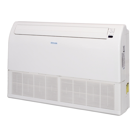
INDOOR UNITS SDV6
COMMERCIAL AIR CONDITIONERS SDV6
Original instructions
IMPORTANT NOTE:
Read this manual carefully before installing or operating
your new air conditioning unit. Make sure to save this
manual for future reference.
For downloading manual for this pro-
duct, please enter the model name at
this link:
Um das Handbuch für dieses Produkt
herunterzuladen, geben Sie bitte den
Modellnamen für diesen Link ein:
Per scaricare il manuale di questo pro-
dotto, inserisci il nome del modello a
questo link:
Pour télécharger le manuel de ce pro-
duit, veuillez saisir le nom du modèle
sur ce lien:
Para descargar el manual de este pro-
ducto, ingrese la designación del mo-
delo en el siguiente enlace:
1
CONTENTS
1Indoor and outdoor unit compatibility ....................................................2
2R32 System Service...................................................................................3
3Main PCB Ports.........................................................................................7
4Indoor unit settings................................................................................30
5Display Panels.........................................................................................39
6Control....................................................................................................41
7Errors and operation code......................................................................53
8Troubleshooting .....................................................................................55
9Appendix .............................................................................................. 128
2
1
Indoor and outdoor unit compatibility
Before performing maintenance, please confirm that the indoor and outdoor units in the system are compatible with each
other. For specific compatibility relationships, please refer to the table below.
Indoor Unit
SDV5 platform SDV6 platform
Indoor Unit
SDV6 indoor
Outdoor Unit
SDV5 unit
SHR
AHU-Kit
SDV6 unit
DC
SDV4F SDV4-XXXEAF








√

√

√

×
SDV4





platform
Mini SDV4


√

√

√

×
SDV5 ind SDV5-***EAI


√

√

√

√


√

√

√

√


√

√

√

√
SDV5


√

√

√

√
Outdoor
platform





Unit















SDV6 ind.
SDV6-EXXXASI


√

×

√

√


√

×

√

√
SDV6





platform





√
SDV6 Mini R410A


√


√

√
Notes:
√represents compatibility, ×represents incompatibility
SDV4-XXXEAA
Ind. SDV4 SDV4-XXXEAA
SDV5 mod SDV5-***EAM
SDV5 ind SDV5-***EAS
Mini SDV5 SDV5-***EAS
SDV5 3P SDV5-***EA3P √ √ √√
SDV6-EXXXATI
SDV6 ind
SDV6 mod.SDV6-ExxxATM
SDV6 Mini R32 SDV6-ExxBS
√√√
×
×××
SDV6-ExxAS ×
3
2R32 System Service
Indoor units in this manual can be used with both R410A and R32 refrigerant systems. When repairing systems that use
R32 refrigerant, the following warnings and operating requirements should be noted.
2.1 Warning about the R32 refrigerant
The following information indicates a hazard with a medium level of risk which, if not avoided, could
result in death or serious injury.
The following applies to R32 refrigerant systems.
Prior to beginning work on systems containing flammable refrigerants, safety checks are necessary to ensure that the
risk of ignition is minimized.
For repair to the refrigerating system, the following precautions shall be complied with prior to conducting work on the
system.
Work shall be undertaken under a controlled procedure so as to minimise the risk of a flammable gas or vapour being
present while the work is being performed.
All maintenance staff and others working in the local area shall be instructed on the nature of work being carried out.
Work in confined spaces shall be avoided. The area around the workspace shall be sectioned off. Ensure that the
conditions within the area have been made safe by control of flammable material.
The area shall be checked with an appropriate refrigerant detector prior to and during work, to ensure the technician is
aware of potentially flammable atmospheres.
Ensure that the leak detection equipment being used is suitable for use with flammable refrigerants, i.e. non-sparking,
adequately sealed or intrinsically safe.
If any hot work is to be conducted on the refrigeration equipment or any associated parts, appropriate fire extinguishing
equipment shall be available to hand. Have a dry powder or CO2 fire extinguisher adjacent to the charging area.
No person carrying out work in relation to a refrigeration system which involves exposing any pipe work that contains or
has contained flammable refrigerant shall use any sources of ignition in such a manner that it may lead to the risk of fire
or explosion.
All possible ignition sources, including cigarette smoking, should be kept sufficiently far away from the site of
installation, repairing, removing and disposal, during which flammable refrigerant can possibly be released to the
surrounding space.
Prior to work taking place, the area around the equipment is to be surveyed to make sure that there are no flammable
hazards or ignition risks. “No Smoking” signs shall be displayed.
Ensure that the area is in the open or that it is adequately ventilated before breaking into the system or conducting any
hot work. A degree of ventilation shall continue during the period that the work is carried out. The ventilation should
safely disperse any released refrigerant and preferably expel it externally into the atmosphere.
Where electrical components are being changed, they shall be fit for the purpose and to the correct specification. At all
times the manufacturer’s maintenance and service guidelines shall be followed. If in doubt consult the manufacturer’s
technical department for assistance.
4
The following checks shall be applied to installations using flammable refrigerants:
–the charge size is in accordance with the room size within which the refrigerant containing parts are installed;
–the ventilation machinery and outlets are operating adequately and are not obstructed;
–if an indirect refrigerating circuit is being used, the secondary circuit shall be checked for the presence of refrigerant;
–marking to the equipment continues to be visible and legible. Markings and signs that are illegible shall be corrected;
–refrigeration pipe or components are installed in a position where they are unlikely to be exposed to any substance
which may corrode refrigerant containing components, unless the components are constructed of materials which are
inherently resistant to being corroded or are suitably protected against being so corroded.
Repair and maintenance to electrical components shall include initial safety checks and component inspection
procedures.
If a fault exists that could compromise safety, then no electrical supply shall be connected to the circuit until it is
satisfactorily dealt with. If the fault cannot be corrected immediately but it is necessary to continue operation, an
adequate temporary solution shall be used. This shall be reported to the owner of the equipment so all parties are
advised.
Initial safety checks shall include:
-that capacitors are discharged: this shall be done in a safe manner to avoid possibility of sparking;
-that no live electrical components and wiring are exposed while charging, recovering or purging the system;
-that there is continuity of earth bonding.
During repairs to sealed components, all electrical supplies shall be disconnected from the equipment being worked
upon prior to any removal of sealed covers, etc. If it is absolutely necessary to have an electrical supply to equipment
during servicing, then a permanently operating form of leak detection shall be located at the most critical point to warn
of a potentially hazardous situation.
Particular attention shall be paid to the following to ensure that by working on electrical components, the casing is not
altered in such a way that the level of protection is affected. This shall include damage to cables, excessive number of
connections, terminals not made to original specification, damage to seals, incorrect fitting of glands, etc.
Ensure that seals or sealing materials have not degraded such that they no longer serve the purpose of preventing the
ingress of flammable atmospheres.
Replacement parts shall be in accordance with the manufacturer’s specifications.
Do not apply any permanent inductive or capacitance loads to the circuit without ensuring that this will not exceed the
permissible voltage and current permitted for the equipment in use.
Intrinsically safe components are the only types that can be worked on while live in the presence of a flammable
atmosphere. The test apparatus shall be at the correct rating.
Replace components only with parts specified by the manufacturer. Other parts may result in the ignition of refrigerant
in the atmosphere from a leak.
Check that cabling will not be subject to wear, corrosion, excessive pressure, vibration, sharp edges or any other adverse
environmental effects. The check shall also take into account the effects of ageing or continual vibration from sources
such as compressors or fans.
When breaking into the refrigerant circuit to make repairs – or for any other purpose – conventional procedures shall be
used. However, it is important that best practice is followed.
5
Since flammability is a consideration. The following procedure shall be adhered to:
•remove refrigerant;
•purge the circuit with inert gas;
•evacuate;
•purge again with inert gas;
•open the circuit by cutting or brazing.
The refrigerant charge shall be recovered into the correct recovery cylinders. The system shall be “flushed” with OFN to
render the unit safe. This process may need to be repeated several times. Compressed air or oxygen shall not be used
for this task.
Flushing shall be achieved by breaking the vacuum in the system with OFN and continuing to fill until the working
pressure is achieved, then venting to atmosphere, and finally pulling down to a vacuum.
This process shall be repeated until no refrigerant is within the system. When the final OFN charge is used, the system
shall be vented down to atmospheric pressure to enable work to take place.
This operation is absolutely vital if brazing operations on the pipe-work are to take place.
Ensure that the outlet for the vacuum pump is not close to any ignition sources and there is ventilation available. Ensure
that contamination of different refrigerants does not occur when using charging equipment. Hoses or lines shall be as
short as possible to minimise the amount of refrigerant contained in them. Prior to recharging the system it shall be
pressure tested with OFN.
DD.12 Decommissioning:
Before carrying out this procedure, it is essential that the technician is completely familiar with the equipment and all
its detail. It is recommended good practice that all refrigerants are recovered safely. Prior to the task being carried out,
an oil and refrigerant sample shall be taken in case analysis is required prior to re-use of reclaimed refrigerant. It is
essential that electrical power is available before the task is commenced.
a) Become familiar with the equipment and its operation.
b) Isolate system electrically.
c) Before attempting the procedure ensure that:
•mechanical handling equipment is available, if required, for handling refrigerant cylinders;
•all personal protective equipment is available and being used correctly;
•the recovery process is supervised at all times by a competent person;
•recovery equipment and cylinders conform to the appropriate standards.
d) Pump down refrigerant system, if possible.
e) If a vacuum is not possible, make a manifold so that refrigerant can be removed from various parts of the system.
f) Make sure that cylinder is situated on the scales before recovery takes place.
g) Start the recovery machine and operate in accordance with manufacturer's instructions.
h) Do not overfill cylinders. (No more than 80 % volume liquid charge).
i) Do not exceed the maximum working pressure of the cylinder, even temporarily.
j) When the cylinders have been filled correctly and the process completed, make sure that the cylinders and the
equipment are removed from site promptly and all isolation valves on the equipment are closed off.
k) Recovered refrigerant shall not be charged into another refrigeration system unless it has been cleaned and checked.

Equipment shall be labelled stating that it has been de-commissioned and emptied of refrigerant. The label shall be
dated and signed. Ensure that there are labels on the equipment stating the equipment contains flammable refrigerant.
When removing refrigerant from a system, either for servicing or decommissioning, it is recommended good practice
that all refrigerants are removed safely.
6
When transferring refrigerant into cylinders, ensure that only appropriate refrigerant recovery cylinders are employed.
Ensure that the correct number of cylinders for holding the total system charge are available. All cylinders to be used are
designated for the recovered refrigerant and labelled for that refrigerant (i.e. special cylinders for the recovery of
refrigerant). Cylinders shall be complete with pressure relief valve and associated shut-off valves in good working order.
Empty recovery cylinders are evacuated and, if possible, cooled before recovery occurs.
The recovery equipment shall be in good working order with a set of instructions concerning the equipment that is at
hand and shall be suitable for the recovery of flammable refrigerants. In addition, a set of calibrated weighing scales
shall be available and in good working order. Hoses shall be complete with leak-free disconnect couplings and in good
condition. Before using the recovery machine, check that it is in satisfactory working order, has been properly
maintained and that any associated electrical components are sealed to prevent ignition in the event of a refrigerant
release. Consult manufacturer if in doubt.
The recovered refrigerant shall be returned to the refrigerant supplier in the correct recovery cylinder, and the relevant
Waste Transfer Note arranged. Do not mix refrigerants in recovery units and especially not in cylinders.
If compressors or compressor oils are to be removed, ensure that they have been evacuated to an acceptable level to
make certain that flammable refrigerant does not remain within the lubricant. The evacuation process shall be carried
out prior to returning the compressor to the suppliers. Only electric heating to the compressor body shall be employed
to accelerate this process. When oil is drained from a system, it shall be carried out safely.
Warning: disconnect the appliance from its power source during service and when replacing parts.
These units are partial unit air conditioners, complying with partial unit requirements of this International Standard,
and must only be connected to other units that have been confirmed as complying to corresponding partial unit
requirements of this International Standard.
2.2 Qualification requirements for maintenance personnel
The following information indicates a hazard with a high level of risk which, if not avoided, will result
in death or serious injury.
These instructions are exclusively intended for qualified contractors and authorised installers
Work on the refrigerant circuit with flammable refrigerant in safety group A2L may only be carried out by authorised
heating contractors. These heating contractors must be trained in accordance with EN 378 Part 4 or IEC 60335-2-40,
Section HH. The certificate of competence from an industry accredited body.
Brazing/soldering work on the refrigerant circuit may only be carried out by contractors certified in accordance with ISO
13585 and AD 2000, Datasheet HP 100R. And only by contractors qualified and certified for the processes to be carried out.
The work must fall within the range of applications purchased and be carried out in accordance with the prescribed
procedures. Soldering/brazing work on accumulator connections requires certification of personnel and processes by a
notified body according to the Pressure Equipment Directive (2014/68/EU).
Work on electrical equipment may only be carried out by a qualified electrician.
Before initial commissioning, all safety relevant points must be checked by the particular certified heating contractors. The
system must be commissioned by the system installer or a qualified person authorised by the installer.
7
3Main PCB Ports
3.1 Compact Four-way Cassette
Figure 3.1:Compact Four-way Cassette main PCB port
Table 3.1: Compact Four-way Cassette main PCB ports
Label in
Figure 3.1 Code Content Port voltage Note
1CN1(L,N) AC power input 220V AC Standard
2CN22
(ALARM,N,AC2)
AC power output used for customization function:
alarm/strong electric sterilization module 220V AC Standard
3CN12(H-L)
CN29(H-N) Reserved 220V AC Reserved
4CN4 Program burning port(fan motor) 5V DC[5] Standard
5CN55 Remote on/off switch connection Note 5 Standard
6CN21 T1 Ambient temperature sensor connection 3.3V DC Standard
7CN35 Humidity sensor connection 3.3V DC Standard
8CN18 Switch Board 5V/12V DC[5] Standard
9CN10(M1M2) M1 M2 communication port(with ODU by
HyperLink) 24V DC Standard
10 CN6(X1X2,PQ) X1 X2 communication port(with wire controller);
P Q communication port(with ODU by RS-485)
X1 X2:18V DC ;
P,E or Q,E: 2.5-2.7V DC Standard
11 CN2(D1D2) D1 D2 communication port(with Central controller) 2.5 - 2.7V DC Standard
12 CN5 Water level port 3.3V DC Standard
13 CN190 DC Drainage pump port 12V DC Standard
14 CN30 Display panel connection 12V DC Standard
15 CN8 EEV drive port 12V DC[5] Standard
16 CN11 T2 Temperature sensor connection 3.3V DC Standard
17 CN15 T2B Temperature sensor connection 3.3V DC Standard
18 CN80 T2A Temperature sensor connection 3.3V DC Standard
19 CN-ASterilization module port 12V DC Standard
20 CN16 Reserved 3.3V DC Reserved
21 CN25 Program burning port(indoor unit) 3.3V DC Standard
22 CN100 Power supply for fan motor Actual voltage Standard
23 CN99 After-sale Kit communication port 12VDC Standard
18
19
23
22
1
2
4
7
8
9
10
11
12 13 14 15 17
16 21
3
5
20
6
8
Notes:
1. Standard: The port is standard, the customers can connect corresponding device through this port, such as water pump and Humidity sensor etc.
Customized: The port is not available on the mainboard. If necessary, you need to customize the port
Reserved: This port can not be used.
2. When repairing, PQ connects after-sales tooling
3. PQ and M1M2 communication ports both are used for indoor and outdoor communication, and only one of them can be used at a time. Meanwhile, be
sure to connect the same communication ports (PQ to PQ; M1M2 to M1M2) in case of damage of the main control board.
4. D1D2 communication ports are used for group control communication. When connecting the group controller, the D1D2 port of the indoor units that are
to be group controlled must be connected in daisy chain, and the group controller must be connected to the X1X2 port of one of the indoor units in the
group control, and set to group control mode. In addition, D1D2 communication ports can also be connected to the central controller.
5. Refer to Table 3.2 for voltage test instructions of some ports.
Table 3.2: voltage test instructions
Code Content Description Picture
CN4 Program burning
port(fan motor) /
CN55 Remote on/off switch
connection
Shorting pins 2 and 3, forced shutdown of
the internal machine (default), can be set by
controller (N38)
CN35Humidity sensor
connection
Using the DC voltage gear of the multimeter
to test pin 4 and 5, the value should be 3.3V
CN18 Switch Board
connection
Using the DC voltage gear of the multimeter
to test pin 1 and 2, the value should be 5V;
Using the DC voltage gear of the multimeter
to test pin 4 and 5, the value should be 12V
CN5 Water level port
The water level is normal, the water level
switch is in the channel state; when the
water level is full, the water level switch is in
the disconnected state
1 pin
3.3V
GND
GND2 (1 pin) 5V 12V
GND
1 pin GND
5V (1 pin )
DGND
1 pin GND
9
Table 3.2: voltage test instructions (continue)
Code Content Description Description
CN190 Drainage pump port When the water pump is running, pin 2 and 3
output 12V DC
CN30 Display panel
connection
Using the DC voltage gear of the multimeter
to test pin 1 and 4, the value should be 12V;
CN8 EEV drive port
Using the DC voltage gear of the multimeter
to test pin 5 and GND (use other ports’
GND) , the value should be 12V;
Using other ports’ GND
CN25 Program burning
port(indoor unit) /
CN99 After-sale Kit
communication port
Using the DC voltage gear of the multimeter
to test pin 1 and 2, the value should be 12V;
GND
1 pin
1 pin
3.3V (1 pin)
GND
GND-L
1 pin
GND 12V (1 pin)
10
3.2 Four-way Cassette
Figure 3.2: Four-way Cassette main PCB ports
Table 3.3: Four-way Cassette main PCB ports
Label in
Figure 3.2 Code Content Port voltage Note
1CN1(L,N) AC power input 220V AC Standard
2CN22
(ALARM,N,AC2)
AC power output used for customization function:
alarm/strong electric sterilization module 220V AC Standard
3CN12(H-L)
CN29(H-N) Reserved 220V AC Reserved
4CN4 Program burning port(fan motor) 5V DC[5] Standard
5CN55 Remote on/off switch connection Note 5 Standard
6CN21 T1 Ambient temperature sensor connection 3.3V DC Standard
7CN35 Humidity sensor connection 3.3V DC Standard
8CN18 Switch Board 5V/12V DC[5] Standard
9CN10(M1M2) M1 M2 communication port(with ODU by HyperLink) 24V DC Standard
10 CN6(X1X2,PQ) X1 X2 communication port(with wire controller);
P Q communication port(with ODU by RS-485)
X1 X2:18V DC ;
P,E or Q,E: 2.5-2.7V DC Standard
11 CN2(D1D2) D1 D2 communication port(with Central controller) 2.5 - 2.7V DC Standard
12 CN5 Water level port 3.3V DC Standard
13 CN190 DC Drainage pump port 12V DC Standard
14 CN30 Display panel connection 12V DC Standard
15 CN8 EEV drive port 12V DC[5] Standard
16 CN11 T2 Temperature sensor connection 3.3V DC Standard
17 CN15 T2B Temperature sensor connection 3.3V DC Standard
18 CN80 T2A Temperature sensor connection 3.3V DC Standard
19 CN-ASterilization module port 12V DC Standard
20 CN16 Reserved 3.3V DC Reserved
21 CN25 Program burning port(indoor unit) 3.3V DC Standard
22 CN100 Power supply for fan motor Actual voltage Standard
23 CN99 After-sale Kit communication port 12VDC Standard
23
22
1
2
4
7
8
9
10
11
12 13 14 15 17
16 21
3
5
20
6
19
18
11
Notes:
1. Standard: The port is standard, the customers can connect corresponding device through this port, such as water pump and Humidity sensor etc.
Customized: The port is not available on the mainboard. If necessary, you need to customize the port
Reserved: This port can not be used.
2. When repairing, PQ connects after-sales tooling
3. PQ and M1M2 communication ports both are used for indoor and outdoor communication, and only one of them can be used at a time. Meanwhile, be
sure to connect the same communication ports (PQ to PQ; M1M2 to M1M2) in case of damage of the main control board.
4. D1D2 communication ports are used for group control communication. When connecting the group controller, the D1D2 port of the indoor units that are
to be group controlled must be connected in daisy chain, and the group controller must be connected to the X1X2 port of one of the indoor units in the
group control, and set to group control mode. In addition, D1D2 communication ports can also be connected to the central controller.
5. Refer to Table 3.2 for voltage test instructions of some ports.
12
Table continued on next page …
23
12
3
3.3
Duct Low static pressure
Figure 3.3: Duct
main PCB ports
4
5
6
7
8
9
10
11
12
13
14
15
16
17
18 19
20
21
Table 3.4: Duct
main PCB ports
Label in
Code
Content
Port voltage
Note
Figure 3.3
1
CN1(L.N)
AC power input
220V AC
Standard
CN22
AC power output
Used for customization function:
2
220V AC
Standard
(ALARM,N,AC2)
alarm/Strong electric sterilization module
CN12(H-L)
3
Reserved
220V AC
Reserved
CN29(H-N)
4
CN100
Power supply for fan motor
Actual voltage
Standard
5
CN4
Program burning port(fan motor)
5V DC[5]
Standard
6
CN80
T2A Temperature sensor connection
3.3V DC
Standard
22
13
Table 3.4: Duct
main PCB ports (continued)
Label in
Code
Content
Port voltage
Note
Figure 3.3
7
CN81
T2 Temperature sensor connection
3.3V DC
Standard
8
CN82
T1 Ambient
Temperature sensor connection
3.3V DC
Standard
9
CN83
T2B Temperature sensor connection
3.3V DC
Standard
10
CN-A
Sterilization module
port
12V DC
Standard
11
CN30
Display Panel
connection
12V DC[5]
Standard
12
CN35
Humidity
sensor
connection
3.3V DC[5]
Standard
13
CN5
Water level port
3.3V DC[5]
Standard
14
CN190
Drainage pump port
12V DC[5]
Standard
15
CN18
Switch Board
5V/12V DC[5]
Standard
16
CN16
Reserved
12V DC
Reserved
17
CN25
Program burning port(indoor unit)
3.3V DC[5]
Standard
18
CN8
EEV drive port
12V DC[5]
Standard
19
CN55
Remote on/off switch connection
Note 5
Standard
X1 X2:18V DC ;
X1
X2 communication port(with wire controller);
20
CN6(X1X2,PQE)
P,E
or Q,E:
Standard
P Q communication port(with ODU by RS-485)
2.5-2.7V DC
D1,E or D2,E
21
CN2(D1D2)
D1 D2 communication port(with
Central controller)
Standard
2.5 -
2.7V DC
22
CN10(M1M2)
M1 M2
communication port(with ODU by HyperLink)
24V DC
Standard
23
CN99
After-sale Kit communication port
12V DC[5]
Standard
Notes:
1.
Standard: The port
is standard, the
customers can connect corresponding device through this port, such as water pump and Humidity sensor etc.
Customized:
The
port is not available on the mainboard. If necessary, you need to customize the port
Reserved: This port can
not be used.
2.
When repairing, PQ connects after-sales tooling
3.
PQ and M1M2 communication ports both are used for indoor and outdoor communication, and only one of them can be used at a tim
e. Meanwhile, be
sure to connect the same communication ports (PQ to PQ; M1M2 to M1M2) in case of damage of the main control board.
4.
D1D2 communication ports are used for group control communication. When connecting the group controller, the D1D2 port of the
indoor units that are
to be group controlled must be connected in daisy chain, and the group controller must be connected to the X1X2 port of one of the indoor units in the
group control, and set to group control mode. In addition, D1D2 communication ports can also be connected to the central controller.
5.
Refer to Table 3.2
for voltage test instructions of some ports.
14
3.4 Medium Static Pressure Duct
Figure 3.4: Medium Static Pressure Duct main PCB ports
Table 3.5: Medium Static Pressure Duct main PCB ports
Label in
Figure 3.4 Code Content Port voltage Note
1CN1(L.N) AC power input 220V AC Standard
2CN22
(ALARM,N,AC2)
AC power output Used for customization function:
alarm/Strong electric sterilization module 220V AC Standard
3CN12(H-L)
CN29(H-N) Reserved 220V AC Reserved
4CN100 Power supply for fan motor Actual voltage Standard
5CN4 Program burning port(fan motor) 5V DC[5] Standard
6CN80 T2A Temperature sensor connection 3.3V DC Standard
Table continued on next page …
23 12
3
4
5
6
7
8
9
10
11
12
13
14
15
16
17
18 19
20 21
22
15
Table 3.5: Medium Static Pressure Duct main PCB ports (continued)
Label in
Figure 3.4 Code Content Port voltage Note
7CN81 T2 Temperature sensor connection 3.3V DC Standard
8CN82 T1 Ambient Temperature sensor connection 3.3V DC Standard
9CN83 T2B Temperature sensor connection 3.3V DC Standard
10 CN-ASterilization module port 12V DC Standard
11 CN30 Display Panel connection 12V DC[5] Standard
12 CN35 Humidity sensor connection 3.3V DC[5] Standard
13 CN5 Water level port 3.3V DC[5] Standard
14 CN190 Drainage pump port 12V DC[5] Standard
15 CN18 Switch Board 5V/12V DC[5] Standard
16 CN16 Reserved 12V DC Reserved
17 CN25 Program burning port(indoor unit) 3.3V DC[5] Standard
18 CN8 EEV drive port 12V DC[5] Standard
19 CN55 Remote on/off switch connection Note 5 Standard
20 CN6(X1X
2,PQE)
X1 X2 communication port(with wire controller);
P Q communication port(with ODU by RS-485)
X1 X2:18V DC ;
P,E or Q,E:
2.5-2.7V DC
Standard
21 CN2(D1D
2) D1 D2 communication port(with Central controller) D1,E or D2,E
2.5 - 2.7V DC Standard
22 CN10(M1
M2) M1 M2 communication port(with ODU by HyperLink) 24V DC Standard
23 CN99 After-sale Kit communication port 12V DC[5] Standard
Notes:
1. Standard: The port is standard, the customers can connect corresponding device through this port, such as water pump and Humidity sensor etc.
Customized: The port is not available on the mainboard. If necessary, you need to customize the port
Reserved: This port can not be used.
2. When repairing, PQ connects after-sales tooling
3. PQ and M1M2 communication ports both are used for indoor and outdoor communication, and only one of them can be used at a time. Meanwhile, be
sure to connect the same communication ports (PQ to PQ; M1M2 to M1M2) in case of damage of the main control board.
4. D1D2 communication ports are used for group control communication. When connecting the group controller, the D1D2 port of the indoor units that are
to be group controlled must be connected in daisy chain, and the group controller must be connected to the X1X2 port of one of the indoor units in the
group control, and set to group control mode. In addition, D1D2 communication ports can also be connected to the central controller.
5. Refer to Table 3.2 for voltage test instructions of some ports.
16
3.5 Wall Mounted
Figure 3.5: Wall Mounted main PCB ports
Table 3.6: Wall Mounted main PCB ports
Label in
Figure 3.5 Code Content Port voltage Note
1CN1(L,N) AC power input 220V AC Standard
2CN22
(ALARM,N,AC2)
AC power output used for customization function:
alarm/strong electric sterilization module 220V AC Standard
3CN12(H-L)
CN29(H-N) Reserved 220V AC Reserved
4CN4 Program burning port(fan motor) 5V DC[5] Standard
5CN55 Remote on/off switch connection Note 5 Standard
6CN21 T1 Ambient temperature sensor connection 3.3V DC Standard
7CN35 Humidity sensor connection 3.3V DC Standard
8CN18 Switch Board 5V/12V DC[5] Standard
9CN10(M1M2) M1 M2 communication port(with ODU by
HyperLink) 24V DC Standard
10 CN6(X1X2,PQ) X1 X2 communication port(with wire controller);
P Q communication port(with ODU by RS-485)
X1 X2:18V DC ;
P,E or Q,E: 2.5-2.7V DC Standard
11 CN2(D1D2) D1 D2 communication port(with Central controller) 2.5 - 2.7V DC Standard
12 CN5 Water level port 3.3V DC Standard
13 CN190 DC Drainage pump port 12V DC Standard
14 CN30 Display panel connection 12V DC Standard
15 CN8 EEV drive port 12V DC[5] Standard
16 CN11 T2 Temperature sensor connection 3.3V DC Standard
17 CN15 T2B Temperature sensor connection 3.3V DC Standard
18 CN80 T2A Temperature sensor connection 3.3V DC Standard
19 CN-ASterilization module port 12V DC Standard
20 CN16 Reserved 3.3V DC Reserved
21 CN25 Program burning port(indoor unit) 3.3V DC Standard
22 CN100 Power supply for fan motor Actual voltage Standard
23 CN99 After-sale Kit communication port 12VDC Standard
23
22
1
2
4
7
8
9
10
11
12 13 14 15 17
16 21
3
5
20
6
19
18
17
Notes:
1. Standard: The port is standard, the customers can connect corresponding device through this port, such as water pump and Humidity sensor etc.
Customized: The port is not available on the mainboard. If necessary, you need to customize the port
Reserved: This port can not be used.
2. When repairing, PQ connects after-sales tooling
3. PQ and M1M2 communication ports both are used for indoor and outdoor communication, and only one of them can be used at a time. Meanwhile, be
sure to connect the same communication ports (PQ to PQ; M1M2 to M1M2) in case of damage of the main control board.
4. D1D2 communication ports are used for group control communication. When connecting the group controller, the D1D2 port of the indoor units that are
to be group controlled must be connected in daisy chain, and the group controller must be connected to the X1X2 port of one of the indoor units in the
group control, and set to group control mode. In addition, D1D2 communication ports can also be connected to the central controller.
5. Refer to Table 3.2 for voltage test instructions of some ports.

Other manuals for SDV6

3

Other Sinclair Inverter manuals

Sinclair SDV5 Series User manual

Sinclair

Sinclair SDV5 Series User manual

Sinclair SDV6 SCC-61 Operating manual

Sinclair

Sinclair SDV6 SCC-61 Operating manual

Sinclair SDV4-140HB3P User manual

Sinclair

Sinclair SDV4-140HB3P User manual

Sinclair CCM04 User manual

Sinclair

Sinclair CCM04 User manual

Sinclair SDV5-56FA User manual

Sinclair

Sinclair SDV5-56FA User manual

Sinclair SDV5 Series Operating instructions

Sinclair

Sinclair SDV5 Series Operating instructions

Sinclair SDV5 Series Operating instructions

Sinclair

Sinclair SDV5 Series Operating instructions

Sinclair SDV6-C Series Operating manual

Sinclair

Sinclair SDV6-C Series Operating manual

Sinclair SDV5 Series User manual

Sinclair

Sinclair SDV5 Series User manual

Sinclair SDV5-MOD User manual

Sinclair

Sinclair SDV5-MOD User manual

Sinclair SDV6 Guide

Sinclair

Sinclair SDV6 Guide

Sinclair SDV6-DM Series Operating manual

Sinclair

Sinclair SDV6-DM Series Operating manual

Sinclair SDV6-CC Series Operating manual

Sinclair

Sinclair SDV6-CC Series Operating manual

Sinclair SDV5 Series Guide

Sinclair

Sinclair SDV5 Series Guide

Popular Inverter manuals by other brands

Simder SD-4050 MINI Operator's manual

Simder

Simder SD-4050 MINI Operator's manual

Emotron VSC Series Quick setup guide

Emotron

Emotron VSC Series Quick setup guide

Tigo TSI-7.6K-US quick start guide

Tigo

Tigo TSI-7.6K-US quick start guide

MAKINEX GEN-6P Operator's manual

MAKINEX

MAKINEX GEN-6P Operator's manual

RENON Xcellent Series user manual

RENON

RENON Xcellent Series user manual

Thunder Scientific series 3900 Operation and maintenance manual

Thunder Scientific

Thunder Scientific series 3900 Operation and maintenance manual

MAC3 HydroControllerHCW-MM Standard user manual

MAC3

MAC3 HydroControllerHCW-MM Standard user manual

Powtran PI9100 Series manual

Powtran

Powtran PI9100 Series manual

Darfon MIG240UL00 user manual

Darfon

Darfon MIG240UL00 user manual

Viridian CSI1500 user manual

Viridian

Viridian CSI1500 user manual

PT W16651 owner's manual

PT

PT W16651 owner's manual

AEC TOUGH-3P Series installation manual

AEC

AEC TOUGH-3P Series installation manual

PowMr POW-LVM3K-24V-H user manual

PowMr

PowMr POW-LVM3K-24V-H user manual

DeWalt DG2900 instruction manual

DeWalt

DeWalt DG2900 instruction manual

Generac Power Systems Liquid Cooled Gas Engine Generator Sets None Specification sheet

Generac Power Systems

Generac Power Systems Liquid Cooled Gas Engine Generator Sets None Specification sheet

Fracarro D-Matrix 4S operating instructions

Fracarro

Fracarro D-Matrix 4S operating instructions

Rheem GEN-15S Operator's manual

Rheem

Rheem GEN-15S Operator's manual

SolaX Power A1-HYB-G2 Series Installation and operation manual

SolaX Power

SolaX Power A1-HYB-G2 Series Installation and operation manual

manuals.online logo
manuals.online logoBrands
  • About & Mission
  • Contact us
  • Privacy Policy
  • Terms and Conditions

Copyright 2025 Manuals.Online. All Rights Reserved.