Christini AWD User manual

Service Manual
Page 1
Service Manual
Christini Technologies, Inc.
421 N. 7th Street Suite 200
Philadelphia, PA 19123
215.351.9895
215.351.9896 fax
info@christini.com
Version 1.3

Service Manual
Page 2

Service Manual
Page 3
Table of Contents
Introduction; Tools you’ll need 4
AWD Bike Detail Illustration 5
Bike Disassembly Flowchart 6
White Brothers AWD Fork Removal 7
White Brothers AWD Fork Drive Shaft Maintenance 8
AWD Drive Shaft Removal and Installation 10
AWD Engagement Clutch Detail 13
AWD Engagement Switch Detail 16
AWD Engagement Cam Detail 17
Rear Suspension Detail 18
AWD Bearing Maintenance 19
Routine Maintenance Schedule 20
General Notes 21
AWD Lubrication Guide 22
AWD Troubleshooting 23
Appendix:
Christini AWD Limited Warranty 24
Christini Owner’s Registration Card 25
Front Hub Maintenance 15
Service Manual
Page 4
The CHRISTINI AWD consists of a patented lightweight, inter-
nalized, shaft-driven system that allows the rider to engage
both wheels for additional power when there is "wheel slip".
With the simple flip of a handlebar-mounted switch, the AWD
system provides increased control, traction and stability on
slippery or loose surfaces and unmatched power to climb
steep hills.
Simply stated, when the rear wheel slips — the front wheel
grips.
Congratulations! You own an All Wheel Drive Bicycle
• Allen Wrench Set
• 2, 2.5, 3, 4 with short end (supplied), 5, 6 millimeter
wrenches
• Plastic faced hammer or a rubber mallet
• Large flat bladed screwdriver & small flat bladed screwdriver
• Torx style wrench - included with disk brake set
• 10 millimeter box wrench
• Pair of needle-nose pliers
• Thread Retaining Compound:
• “Blue” Loc-tite 242 Removable Strength
• “Red” Loc-tite 262 Permanent Strength
The Tools You Will Need for Maintenance

Service Manual
Page 5
Page 5
AWD Detail Illustration
Service Manual
Page 6
Page 6
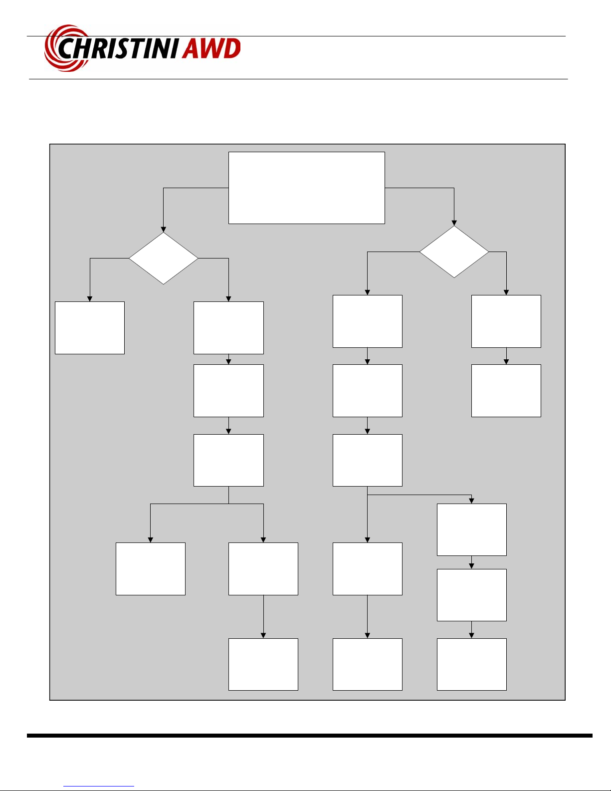
Bike Disassembly Flowchart
Remove Fork
Remove
Front Wheel
Remove Front
Bevel Gear
Remove Chain
Crown Cover
Remove Front
Pinion
Remove
Rear Wheel
Remove
Clutch
Remove Rear
Bevel Gear
Remove Shock
Remove
Suspension
Link
Remove Front
Drive Shaft
Remove Rear
Pinion
Remove Rear
Drive Shaft
Remove Pivot
Bolts
Remove Rear
Triangle
All Wheel Drive Bike
Disassembly Process
Separate the
Front and Rear
Driveshafts
Remove
Headtube
Gear and
Sprocket Shaft
Remove
Power
Transfer Chain
Remove Front
Driveshaft
Service Manual
Page 7
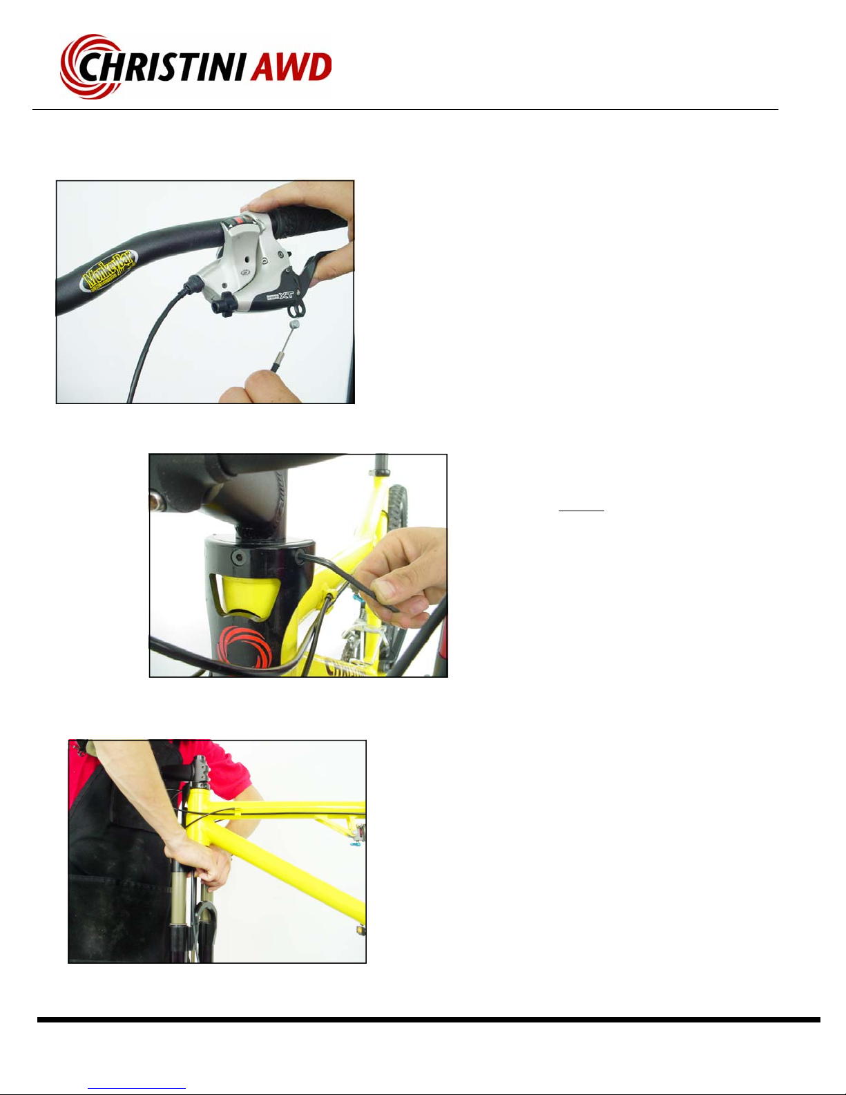
• Remove the front wheel. The fork legs may
need to be pulled apart slightly, since there is
a 1 mm indent on the non-disc brake side of
the front hub axle. This indent locates the
front bevel gear and provides support during
heavy AWD loading.
• Remove the front disk brake cable at the
lever—or remove the front disk brake caliper.
• Remove the three M6 bolts, located just
above the headtube on the front plate, that
attach the steering link to the upper steering
clamp.
• Warning—DO NOT use the rounded Bohndus
end of the Allen wrench when first loosening
the bolts. You will strip the hex head of these
bolts.
• After these three bolts have been removed,
the fork can be pushed down out of the head-
tube of the bicycle. If necessary, use a plastic
hammer to tap the fork out. Hit the hammer
on the top of the brake arch to avoid damag-
ing the forks valves.
• Please refer to the White Brother’s AWD Fork
Owner’s Manual to service or adjust the front
suspension. (If lost see www.WhiteBros.com
for details)
Installation:
• Slide Lower steering tube into the support bear-
ings in the headtube.
• Tap the fork into place with a plastic hammer.
Do not tap the crown cover.
Custom White Brothers AWD Fork Removal
Service Manual
Page 8
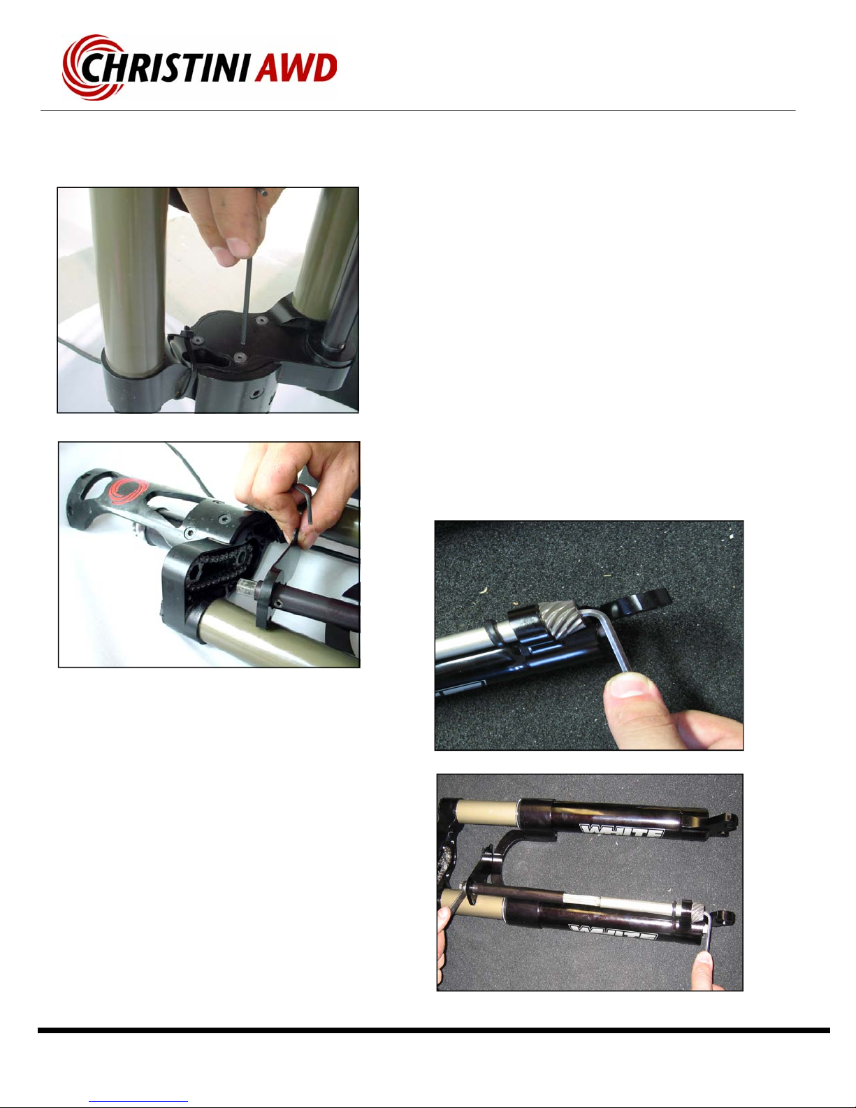
Fork Driveshaft Maintenance
Removal
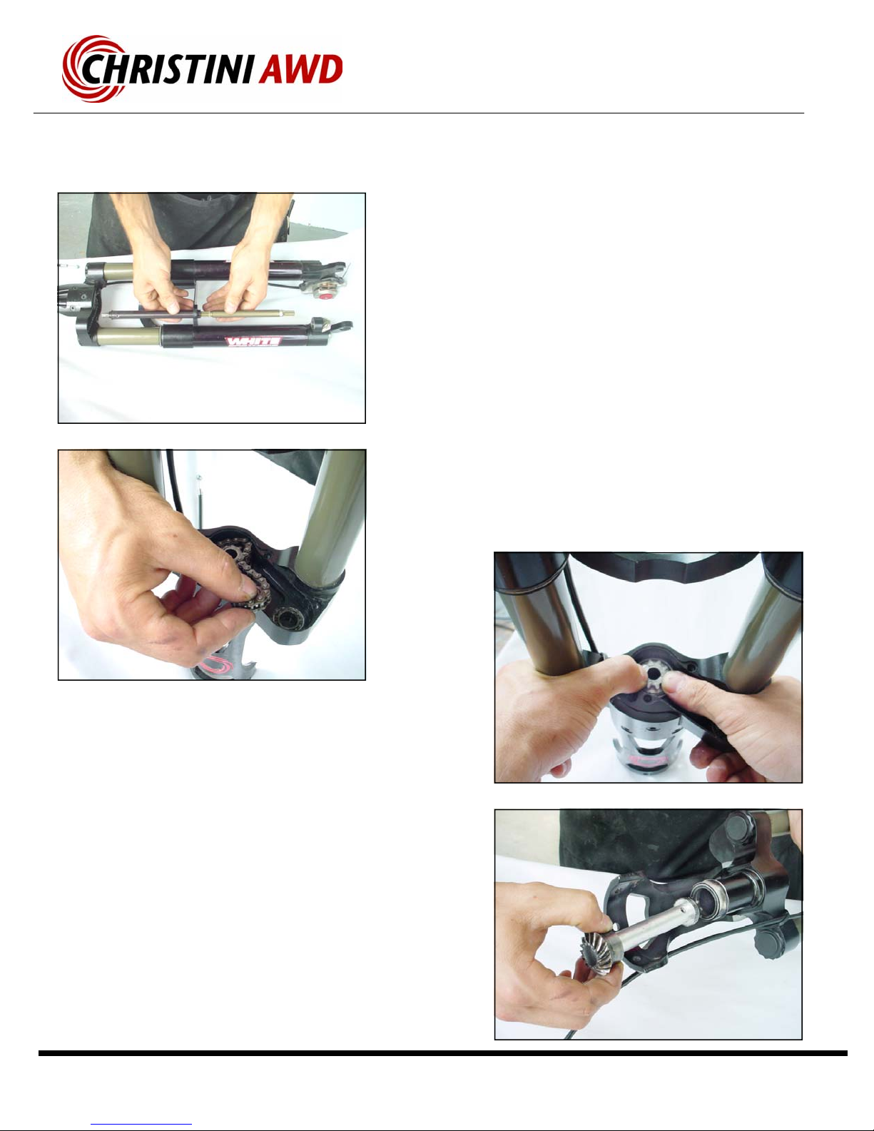
• Remove the four countersunk M4 screws under the
crown of fork which hold the crown cover plate in
place.
• Remove the Crown-Cover plate. Slide the Upper
Front driveshaft and the crown cover plate down, as
shown, towards the dropouts. The Upper Front
Driveshaft will compress and slide on the splined
portion of the drive shaft.
▪Remove the fork drive shaft capture bolt. It is an M6 bolt
on the end of the fork drive shaft located under the pinion gear.
▪To loosen the bolt, use the supplied short-end 4mm Allen
wrench to hold the bolt in position while turning the hex piece
of the driveshaft counterclockwise (from the top of the fork
looking down), with a 10mm box wrench.
▪TIP: If the driveshaft is stuck in the gear, loosen the bolt
halfway and then gently tap the blot head with a hammer to
free the driveshaft.
Service Manual
Page 9
Fork Driveshaft Maintenance
Installation:
▪Insert the drive shaft into the steering tube, sprocket first,
until the miter gear is fully seated on its sealed bearing
support.
▪Loop the chain around the shaft sprocket and the floating
cog. Press the cog into the bearing.
▪Press the upper hex portion of the driveshaft into the cog
and slide the chain crown up into place.
▪Use removable threadlocker when re-installing the crown
cover screws.
▪Use removable threadlocker on the pinion bolt.
Removal:
▪Slide the two sections of the front drive shaft together.
▪The chain crown cover can slide off at this point.
▪The pinion gear can also be removed at this point.
▪Remove the floating cog and power transfer chain from
the internal section of the chain crown.
▪Use your thumbs to press the center sprocket up through
the lower steering tube.
▪Carefully pull the drive shaft out of the steering tube.
Service Manual
Page 10
AWD Frame Drive-system Maintenance
Re-assembly:
▪Slide the rear pinion into the slot and then drop the rear
drive shaft down into the female spline on the pinion.
▪Apply removable threadlocker to the M6 bolt and tighten
by holding the bolt with a wrench and then spin the drive
system clockwise to tighten.
▪Install the rear shock mount bolt and the rear shock.
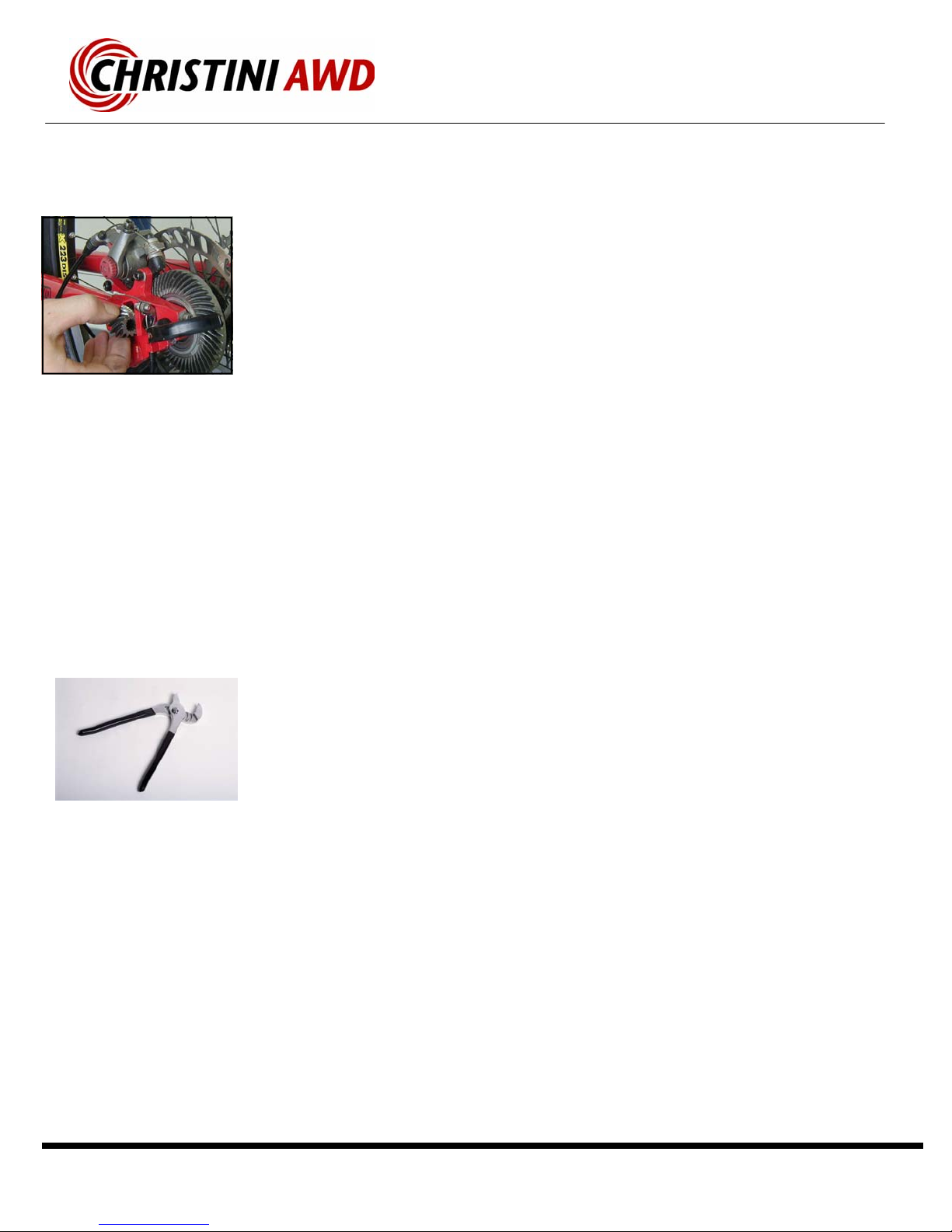
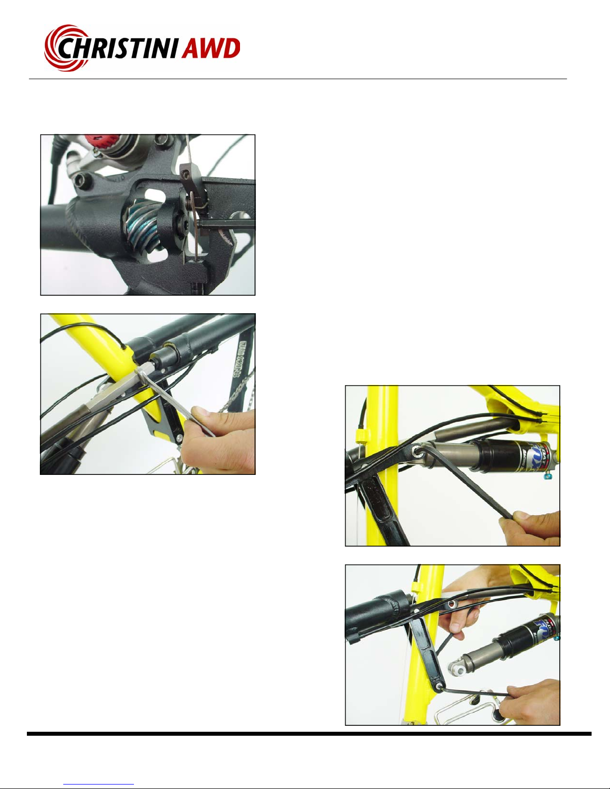
Removal:
▪Remove the M6 capture bolt from the rear pinion assembly on
the rear bevel dropout. Use the supplied short-end Allen Wrench to
hold the bolt while spinning the drive system by hand to remove the
bolt.
▪If necessary, use a 10mm wrench to spin the square spline
section of the drive system to help loosen the bolt.
▪Remove the rear shock mount bolt, and then slide the shock
out from between the Top Yoke, as shown.
▪TIP: Be careful not to chip the frame paint with the suspension
link when the rear triangle swings backward.

Service Manual
Page 11
AWD Frame Drive-system Maintenance
• Gently tap the round female slider section with a flat head
screwdriver and push the front drive shaft, which is attached
to the driving miter gear, out through the access hole in the
headtube.
Removal:
▪Remove the pivot bolt in the lower portion of the
suspension link. If necessary, use an Allen wrench smaller
than the internal threads to punch the female portion out.
▪Carefully lower the rear linkage until the bottom yoke is
resting on the bottom bracket pivot casing.
▪The main drive-shaft will separate at the square splined
universal joint section.
▪Remove the plastic dirt cover from the front of the
headtube access hole.

Service Manual
Page 12
• The entire driveshaft will push through the
support bearings located in the headtube.
• To remove the rear driveshaft, pull it forward
through the support bearings by gripping the
universal joint section.
• The rear drive pinion will slide out from the
dropout slot.
Installation:
• Slide the rear and front drive-shafts into their
respective frame tubes. The front shaft will
slide through the headtube support bearings
and then firmly seat on the edge of the miter
gear. The rear shaft will slide through the sup-
port bearings but may not seat completely on
the u-joint section. There may be a small gap
between the u-joint and the bearing the top
yoke.
• If necessary, replace the rubber u-joint boots.
• Slide the square spline section into the round
female section before you begin to re-attach
the suspension link and the shock.
AWD Frame Drive-System Maintenance
Service Manual
Page 13
AWD Clutch Maintenance
Removal:
▪Remove the rear wheel and quick release skewer.
▪Push down of the top clutch plate and rotate the bevel
gear until the clutch plate does not spring back up.
▪Remove the clutch snap ring from the groove in the top
of the rear bevel gear.
▪Slide the top “sliding jaw” of the clutch up and out of the
guides in the gear assembly.
Installation:
▪Attach the clutch and gear assembly to the rear wheel
(see page 14).
▪Make sure that the engagement cams are in the off
position, they should be flush with the surface of the dropout.
▪Re-install the rear wheel, making sure to seat the axle
completely into the rear dropouts.
▪Test the engagement and disengagement of the clutch.
Service Manual
Page 14
AWD Clutch Maintenance
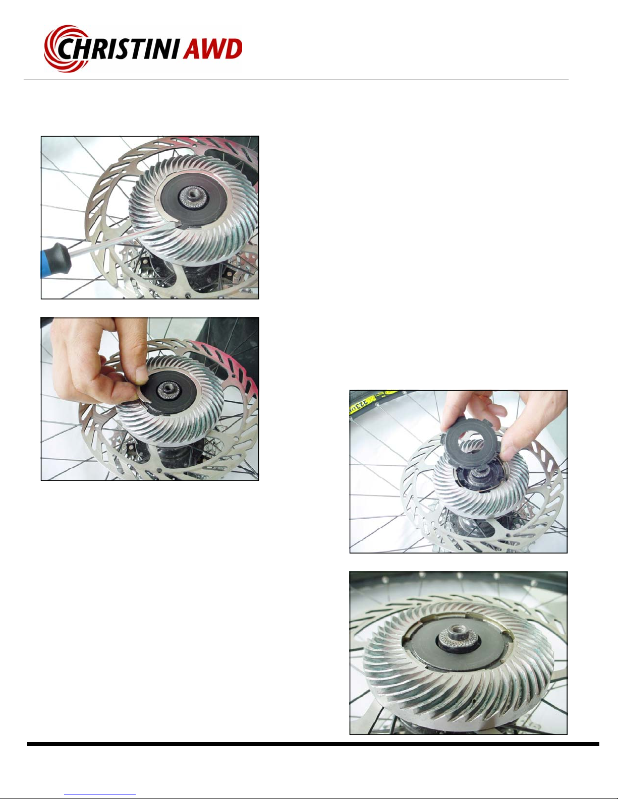
Re-assembly:
▪Press the clutch bearing and locked jaw into the gear.
▪Install the circular wave spring into the locked jaw section
making sure that the broken “tabs” are facing away from
the hub are lined up with a sliding jaw guide slot (top left
picture).
▪Install the sliding clutch plate by lining up the 6 guides
into the appropriate slots, then press down on the plate 4-
5mm and slightly rotate the plate until it does not spring
back up.
▪Install the snap ring and make sure that the clutch is free
to rotate when the sliding jaw is pressed in completely.
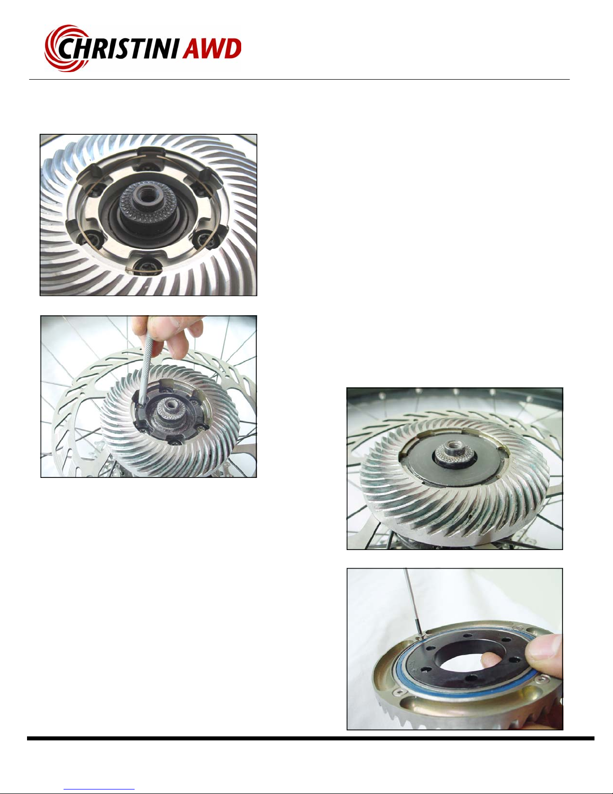
Removal:
▪Remove the circular wave spring.
▪Use a Torx wrench to remove the 6 disk brake bolts that
attach the gear assembly to the disk brake hub.
▪Remove the gear assembly from the hub.
▪To remove the “locked jaw” turn over the gear assembly,
and remove the 4 M3 countersunk bolts that attach the large
diameter clutch bearing to the gear.
▪Press or tap out the locked jaw section from the bearing.
Service Manual
Page 15
Front Hub Maintenance
Re-assembly:
▪Press the axle and freewheel insert back into the hub
shell until the insert is flush with the hubshell bearing. A
plastic hammer may be needed to tap the insert back into
place.
▪Insert the end caps onto the axle and tighten the set
screws.
▪Note: The flat face of the gear side end cap should face
outward.
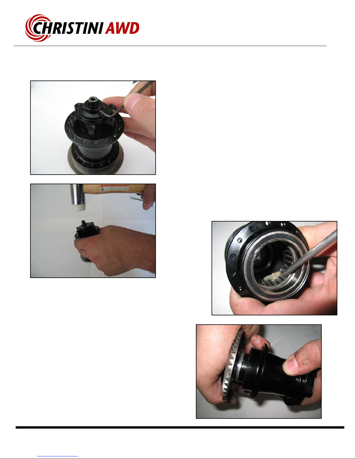
Removal:
▪Loosen the set screws on the end caps and remove them
from the axle.
▪With a plastic hammer, tap the disc side axle to loosen
the freewheel insert. A punch may be needed to
completely free the insert from the hubshell.
▪Remove the freewheel insert and axle from the hub.
▪Apply a light oil or grease to the roller bearings inside the
hubshell.
Note: It is not necessary to remove the bevel gear or the
brake rotor to service the freewheel.
Service Manual
Page 16
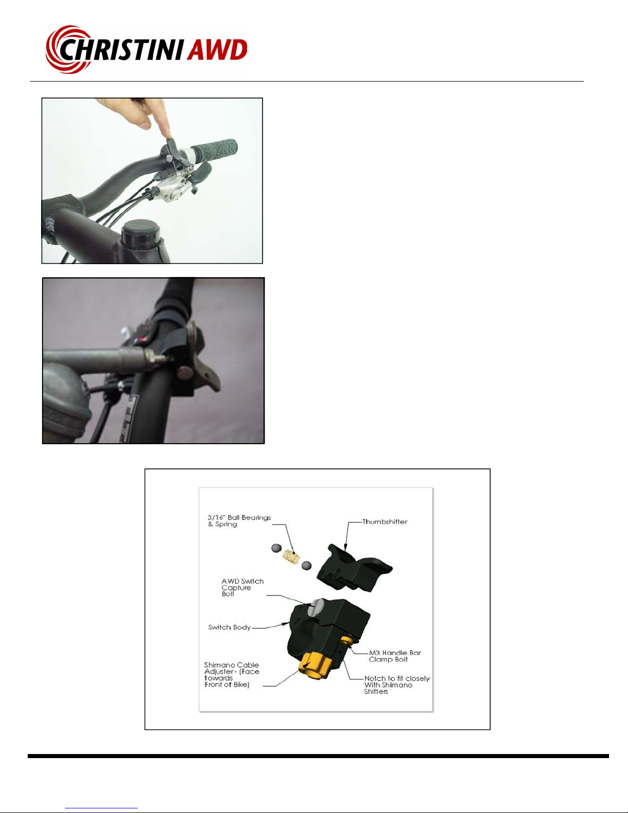
• Install the switch on the handlebar before the shifter
pods and grips. Make sure that the cable adjuster
faces forward.
• Use 2mm Allen wrench to tighten the clamp bolt which
secures the switch to the handlebars.
• Apply grease through the holes in the side of the switch
body directly to the ball bearings if the engagement
switch becomes hard to move.
AWD Engagement Switch Detail
Service Manual
Page 17
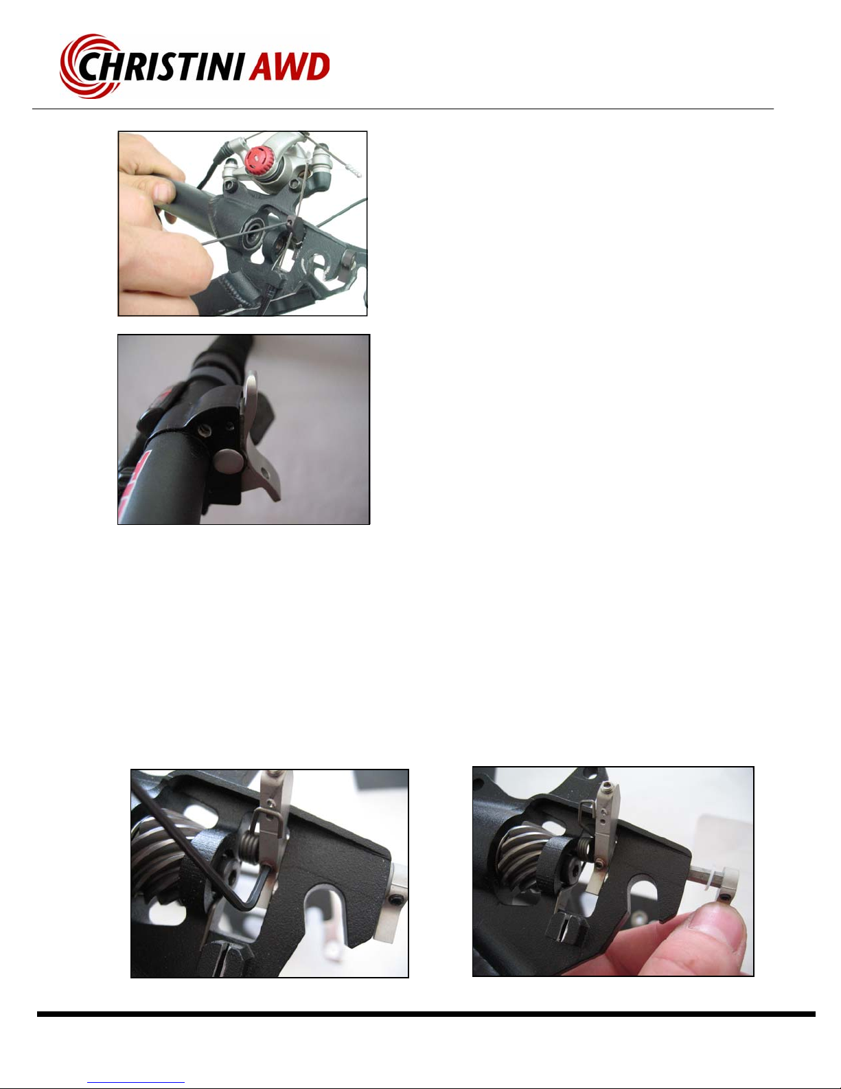
Cable Adjustment:
• To attach the cable from the switch to the en-
gagement cams, loosen the set screw located
in the top of the long cam and slide the cable
through.
• Install the rear wheel and clutch assembly in
the dropouts.
• To adjust the cams, press the engagement
switch down. Pull the cable taunt and tighten
the set screw.
• Adjust the actuation of the system using the
cable adjuster on the AWD switch. Press the
engagement switch up and turn the cable ad-
juster counterclockwise until the lever begins
to pull away from the switch body (second pic-
ture from the top).
• Turn the cable adjuster back 3/4 of a turn and
make sure the ball bearings seat completely in
the switch body holes.
AWD Engagement Cams
Cam Removal:
• To remove the cam system from the
dropouts, loosen the hex set screw on
the long cam.
• Slide the short cam and hex shaft out
from the dropout.
• Remove the long cam, torsion spring
and Teflon washers.

Service Manual
Page 18
• Disassemble the shock by removing the upper
shock bolt using a 5mm Allen wrench and an
10mm box wrench.
• Remove the large bolts where the rear triangle
and the front triangle connect at the suspen-
sion pivot.
• Remove the M8 bolts from the remaining con-
nection between the suspension link and the
rear triangle.
• There is a washer on either side of the
suspension link that needs to be installed
between the link and the rear triangle.
This washer fits through the threaded sec-
tion of upper suspension link bolts.
• During re-assembly—use removable
threadlocker on all pivot bolts.
Rear Triangle Detail

Service Manual
Page 19
• All bearings should rotate smoothly.
• Bearings should be replaced if they begin to
make excessive noise or they feel “notchy”.
• Bearings are sealed and do not require lubri-
cation.
• Please contact Christini if you think a bearing
needs to be replaced.
AWD Bearing Maintenance

Service Manual
Page 20
As Needed
• Wash exposed drive system parts with
soap and water or a bike cleaner.
• Replace bearings if excessive noise or
friction develops.
• Lubricate all spline shafts if suspen-
sion performance is effected.
• Replace worn or damaged mud
guards.
Monthly
• Tighten frame linkage bolts.
• Check disk brake bolts.
• Lubricate headtube gearset with
grease.
• Lubricate the front and rear bevel
gears with chain lube.
Yearly
• Disassemble, clean and inspect the
rear bevel clutch assembly.
• Apply lightweight oil lube to the front
“silent freewheel” hub.
Routine Maintenance Schedule
AVOID:
• Water in the headtube.
• Water inside the frame.
• Mud, dirt, or sand in the u-joints or
gear sets for extended periods.
Table of contents


