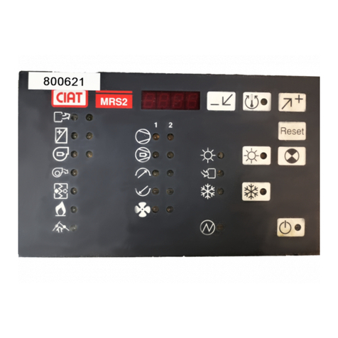
CIAT MAGISTER Series User manual

Instruction manual
MAGISTER®
06 - 2021
EN7558843-03

Original text: French version
CONTENTS
1 - INTRODUCTION.........................................................................................................................................................................3
2 - RECEIPT OF GOODS ................................................................................................................................................................4
2.1 - Checking the equipment.........................................................................................................................................................4
2.2 - Identifying the equipment .......................................................................................................................................................4
2.3 - Documents .............................................................................................................................................................................4
3 - SAFETY INSTRUCTIONS ..........................................................................................................................................................5
4 - WARRANTY................................................................................................................................................................................5
5 - STORAGE OF EQUIPMENT ......................................................................................................................................................5
6 - HANDLING .................................................................................................................................................................................5
7 - SUPPLY AIR TYPE.....................................................................................................................................................................6
8 - LOCATION & INSTALLATION ...................................................................................................................................................7
9 - LOCATION AND MARKING OF COMPONENTS ......................................................................................................................8
10 - CONNECTIONS......................................................................................................................................................................10
10.1 - Hydraulic connection..........................................................................................................................................................10
10.2 - Electrical connection ..........................................................................................................................................................11
11 - TECHNICAL CHARACTERISTICS ........................................................................................................................................14
11.1 - Basic components ..............................................................................................................................................................14
11.2 - Optional components..........................................................................................................................................................17
12 - COMMISSIONING ..................................................................................................................................................................26
13 - MAINTENANCE......................................................................................................................................................................27
13.1 - Filters..................................................................................................................................................................................28
13.2 - Cooling coil.........................................................................................................................................................................29
13.3 - Humidier ...........................................................................................................................................................................30
13.4 - Fans ...................................................................................................................................................................................31
13.5 - Electrics box.......................................................................................................................................................................34
14 - SERVICE INTERVALS............................................................................................................................................................35
15 - OPERATING READINGS .......................................................................................................................................................35
16 - REGULATIONS ......................................................................................................................................................................35
MAGISTER®EN-2

1 - INTRODUCTION
Introduction to the range:
MAGISTER® is a range of precision close control units operating with chilled water (temperature and humidity) that is specically
adapted to meet the needs of premises with high heat loads or of sensitive locations (DATA CENTRES, computer rooms, metrology
laboratories, etc.).
The description of the unit is indicated using the following format:
MAGISTER®X X X
B C D E
Example of description: MAGISTER®CW40 UNDER1
B Range
C Unit type
-CW: chilled water
D Cooling capacity
E Assembly type (direction of air ow)
-UNDER1: Return air above / supply air underneath
-OVER3: Return air in front / supply air above
-OVER5: Return air underneath / supply air above
EN-3 MAGISTER®

2 - RECEIPT OF GOODS
2.1 - Checking the equipment
In accordance with Article 133-3 of the French Code of Commerce, the recipient is entirely responsible for checking the condition
of the goods received.
In the event of missing items, the customer must provide the exact number of parcels delivered.
Any damaged or missing items must be specied on the delivery note in the presence of the driver before signing the delivery note.
These comments must be conrmed to the carrier by registered letter within three business days.
The comments "conditional" and "pending unwrapping" shall have no value.
The client must unwrap the goods in the presence of the driver.
Claims must be made at the time of delivery and be described in detail.
2.2 - Identifying the equipment
Each unit has a nameplate located at the bottom of the electrics box that bears an identication number. This number must be
quoted in all correspondence.
B Product reference
C Product description
D Year of manufacture
E
Serial no. (to be quoted in all correspondence)
F
Type of uid used in the exchanger and operating pressure.
G Cooling capacity + water temperature used
H
Heating capacity + water temperature used (if heating coil option)
+ usage type (2 stages or TRIAC, if electric heater option)
I Information on the vertical unit
-Supply voltage
-Max. current
-Weight of the unit
Designation/Description
Ref. produit/Item Nbr
An(Year)
N. Serie/Serial Nbr
Fluide - Charge/Fluid - Load Froid/Cold Tension/Voltage
Intensité/CurrentRegimeBP/LP Mini
HP Maxi Chaud/Heat Poids/Weight
N° Declaration CERegime - TypeTemp. Maxi (°C)
Repere/Part
02183458/0008
7323226.333462 MAGISTER CW030 3OVER
7033238.12
2014
8
2
76
4
1
3
5
2.3 - Documents
The following documents should be inside the cabinet:
-Instruction manual.
-Control manual.
-Wiring diagram for the vertical unit
-Key to the wiring diagram
-Dimensional drawing with connection diagram
-Additional diagrams depending on options
MAGISTER®EN-4

3 - SAFETY INSTRUCTIONS
Appropriate PPE (Personal Protective Equipment)
must be worn when servicing the units
Warning
The unit must be installed and maintained by a qualified, experienced technician. Follow the operating precautions
to the letter when working on the unit. Labels have been placed on the unit to remind you of the safety instructions.
As a general rule, follow all applicable safety regulations and standards.
4 - WARRANTY
See the general terms and conditions of sale
5 - STORAGE OF EQUIPMENT
The cabinet must be stored in a dry, sealed area, away from moisture and frost. The temperature in this area must not exceed 50 °C.
6 - HANDLING
The unit must be handled either with a pallet truck or using a spreader beam and slings. This operation must be carried out by
qualied personnel. Refer to the information given on the relevant label on the unit.
Important: The unit must be handled with care and kept upright.
In all cases, the vertical unit must be raised by its base.
Handling with a pallet truck
==
EN-5 MAGISTER®

6 - HANDLING
Handling with a spreader beam and slings
1100
2500 mini
To be removed while handling,
then replaced once the vertical
unit is in place
If the unit is lifted using a spreader beam and slings:
-Protect the panels.
-First remove all the caps covering the holes for the tubing on the lower section of the unit. (Fig. 1).
-Use tubing (Ø max. = 40 mm) with a sucient lifting capacity (see weight table).
-Use fabric slings.
6.1 Weights and dimensions:
SIZE Dimensions
H x W x D Weight (kg)
CW 40 1990 x 1190 x 890 350
CW 53 1990 x 1520 x 890 385
CW 78 1990 x 2070 x 890 545
CW 100 1990 x 2620 x 890 635
CW115 1990 x 3000 x 890 730
7 - SUPPLY AIR TYPE
3 supply air types:
Fitting UNDER
Return air above supply
air underneath
Fitting OVER
Return air on front, supply
air above except CW115
Return air underneath, supply
air above except CW115
MAGISTER®EN-6

8 - LOCATION & INSTALLATION
You must leave space for access to the front and to the right of the unit for maintenance and installation operations.
For free air intake, there must be at least 500 mm above the unit.
1000 mm
1000 mm
500 mm
Under no circumstances should these vertical units be installed in an atmosphere that is:
-Explosive,
-Flammable,
-Corrosive, or dusty.
Once at the place of installation, remove the wooden blocks.
-Dierent conguration options are possible:
• The unit can be placed directly on the oor. In this case:
The unit must be placed on a at, smooth surface which is as level as possible (ratio of approx. one to one thousand). The cabinet
frame must rest fully on its contact surface. The unit need not be anchored to the oor if it is operated under normal conditions.
• Or on one of the following bases:
Support base, cased base with grids, cased base with damper.
(See the technical characteristics for these options in paragraph 12.2).
It should be placed on a oor that is as level as possible.
Each base comes with feet, which allow the height to be adjusted (in the event of a raised oor) and the base to be levelled before
placing the unit on top.
Before placing the vertical unit on top, an adhesive seal (supplied with the option) is to be placed on the aluminium casing frame
to ensure its tightness.
The cabinet can also come with a plenum with grids or a free-cooling plenum.
(See the technical specications for these options in paragraph 12.2)
Before placing the plenum on the vertical unit, apply the adhesive seal (supplied with the option) to its tightness.
For practical reasons, when the CW 115 model unit is in its nal position, the
horizontal gussets (with round stamped holes), located at the bottom of the unit, can be removed (see photo).
Horizontal gussets
EN-7 MAGISTER®

9 - LOCATION AND MARKING OF COMPONENTS
CW40 to CW100, Under Assembly
Filters
FMA
FMA access
hatch
Control valve (cooling coil)
Humidier (option)
Heating coil (option)
Control valve (Heating
coil)
Cooling coil
Electrics Box
Cooling coil
Electric heater
(option)
Additional cabinet
Drain pump (option)
Condensate drain
pump (option)
CW40 to CW100, Over Assembly
FMA
Electrics Box
Control valve (Heating
coil)
Cooling coil
Heating coil (option)
Control valve
(cooling coil)
Humidier
(option)
Filters
Cooling coil
Electric heater
(option)
Condensate
drain pump
(option)
Additional cabinet
Drain pump
(option)
MAGISTER®EN-8

CW115, Under Assembly
Electric heater (option)
Access
hatches
Filters
Electrics Box
Cooling coil
Control valve
(cooling coil)
Humidier (Option)
FMA
9 - LOCATION AND MARKING OF COMPONENTS
EN-9 MAGISTER®

10 - CONNECTIONS
When following these steps, please consult the dimensional drawing and connection diagram as well as the wiring diagram found
inside the vertical unit.
10.1 - Hydraulic connection
The hydraulic pipes must be routed through the plates provided for this purpose in the vertical unit frame. This is either done to
the right of the unit or directly underneath.
side plate
These plates must be drilled (water circuit + condensate draining) then retted in place before the hydraulic pipes are routed through
them.
For the CW115 model, the pipes on the right are routed through a xed insulated panel.
Foam panel
please see the dimensional drawing and connection diagram to locate the routing areas and connection positions.
Connection diameters:
CW 40 CW 53 CW 78 CW 100 CW115
Cooling coil
Inlet G 1"1/4 (M) G 1"1/4 (M) G 1"1/2 (M) G 1"1/2 (M) G 1''1/2 (M)
Outlet G 1"1/4 (F) G 1"1/4 (F) G 1"1/2 (F) G 1"1/2 (M) G 1''1/2 (F)
CW 40 CW 53 CW 78 CW 100
Heating coil
Inlet G 3/4" (M) G 3/4" (M) G 3/4" (M) G 3/4" (M)
Outlet G 3/4" (M) G 3/4" (M) G 3/4" (M) G 3/4" (M)
Always use two spanners when connecting or tightening the hydraulic couplings to avoid twisting the pipes and applying stress on
the welds.
To avoid the risk of condensation, the hydraulic pipes and elements must be carefully insulated.
Before insulating, check the tightness of the couplings.
Warning: the operating pressure on the chilled or hot water network must not exceed 8 bar.
Once all the connections have been made, the access holes must be sealed.
Insulated exible connections are available on request for carrying out hydraulic connections. Ensure these are not bent too acutely
to avoid pinching the inner tube and restricting the ow of water.
Condensate drain
The condensate drain pan should include a siphon to avoid any risk of overowing. (See position and connection diameter on the
dimensional drawing).
In these vertical units, the pan is depressed due to its position in relation to the fan motor assembly.
To enable correct drainage, the height must be equal to at least twice the unit's depression.
MAGISTER®EN-10

67
67
A condensate drain pump option is available (see technical specications in paragraph 12), provided that the humidier option has
not been requested.
If the humidier option is selected, the discharge must not drain into the unit's drain pan. To have a single discharge for both,
connect the humidier drain downstream of the unit's drain pan.
Warning: the condensates from the humidier can reach 100 °C.
10.2 - Electrical connection
The electrical connections and wiring must be set up as shown on the wiring diagram included with the unit and in accordance with
applicable standards and regulations.
The unit's power supply cable must be determined according to the power of the unit, the length of the cable, the protection, and
the operating mode.
Check that the characteristics of the electrical power supply conform with the indications on the name plate.
Please ensure the unit is connected to earth, and that the power supply is always able to supply the necessary power.
Electrical specifications: Three-phase 400 V power supply + Earth - 50 Hz
Table of currents
CW 40 CW 53 CW 78 CW 100 CW115
Fan motor assembly
Voltage (V) 400
Power (kW) 3,4 6,8 9,3
Current (A) 5,4 10,8 14,7
Control circuit (transformer)
Voltage (V) 24
Current (A) 1
Humidifier (option)
Voltage (V) 400
Power (kW) 6
Current (A) 8,7
Electric heater (option)
Voltage (V) 400
Power (kW) 12 18 24 33,6 33,6
Current (A) 17,4 26 34,6 48,4 48,4
Total current without option
Current (A) 6,4 6,4 11,8 11,8 15,7
Rating of main switch (A) 16 25
Total current with humidifier
Current (A) 15,1 15,1 20,5 20,5 24,4
Rating of main switch (A) 25 40
Total current with electric heater
Current (A) 23,8 32,4 46,4 60,2 64,1
Rating of main switch (A) 40 63 80
Total current all options
Current (A) 32,5 41,1 55,1 68,9 72,8
Rating of main switch (A) 40 63 80
10 - CONNECTIONS
EN-11 MAGISTER®

Recommendations concerning electrical connections of the indoor unit.
Connect the indoor unit so that the main power supply comes from underneath the unit.
Either on the right side of the unit (1 or 2) or from underneath (3). If using a cased base, pass it through one of the grommets on
the right side intended for this purpose (See technical characteristics in paragraph 12.2.5).
B
C
D
Then follow the routing shown in the gures below.
Cable routing for management
(CMS) or room sensors.
Power supply cable
route
CW model CW115 model
When wiring via management systems (CMS) or master/slave control, as well as room sensors, go through the top of the cabinet
and the top section of the box, through the grommets shown in the box views.
In all cases, avoid following the power supply cables, to avoid interference to the signals sent.
Recommendations concerning the cables and routing in the box.
-For the communication cables:
• BUS RS485 cable: Multiconductor shielded jacketed cable (shielding with braiding)
- BUS RS485 cable for MODBUS or master/slave communication.
- BACNET BUS cable for BACNET communication (see BACNET specication)
-For the room sensor cables:
• Multipolar shielded cables of 3 to 5 wires with a maximum cross section of 1.5 mm2.
Please refer to the control manual and electrical diagram for more details concerning connection.
10 - CONNECTIONS
MAGISTER®EN-12

Inlets Inlet
CW 40 to 100 models CW115 model
Recommended
route for BUS RS
485 cable Raceways
Raceways
Route for
BACNET
BUS cable
Gateway
BACNET
All the cable routings in the unit must be sealed tight.
The CW115 model is supplied with covers which must be tted on the side and front section of the casing.
10 - CONNECTIONS
EN-13 MAGISTER®

11 - TECHNICAL CHARACTERISTICS
11.1 - Basic components
11.1.1 - Control
The vertical units are equipped with a CIAT µAIR CONNECT2 automatic control unit.
CIAT µ Air Connect 2
The heart of the vertical unit, this manages the unit and ensures it functions correctly. It is built into the display.
It can be connected to control systems so that the vertical unit can be controlled remotely, or to allow for master/slave control with
several vertical units.
For adjustment and conguration, refer to the corresponding manual (N09.41).
11.1.2 - Fan motor assembly (FMA)
EC motor (electronic communication) with "plug fan" type direct drive.
Thanks to their technology, these fans have low energy consumption.
Type of FMA control:
-With the µRC2.1 control
• On CW40 to 100 vertical units: MODBUS control as the FMAs are equipped with a MODBUS card that sends the following
information to the controller: rotation speed, current used and power input.
• On CW115 vertical units: progressive 0-10 V control.
-No control
• Progressive 0-10 V control via a manual voltage potentiometer located inside the electrics box (graduated from 0 to 100 %)
CHILLED WATER
CW 40 CW 53 CW 78 CW 100 CW115
Quantity 11223
Max. power (kW) 3,4 3,4 6,8 6,8 9,3
Max. current (A) 5,4 5,4 10,8 10,8 14,7
MAGISTER®EN-14

Nominal ow rates of cabinets:
CHILLED WATER
CW 40 CW 53 CW 78 CW 100 CW115
Nominal flow rate (m³/h) 10000 13300 18800 24500 27000
Max. flow rate (m³/h) 13300 13300 20500 27000 27500
Table of operating pressures downstream of the filters
CW CW 40 CW 53 CW 78 CW 100 CW115
Air ow (m3/h)
Rated Maximum Rated Maximum Rated Maximum Rated Maximum Rated Maximum
10 000 13 300 13 300 13 300 18 800 20 500 24 500 27000 27 000 27 500
Max. operating pressure with G4/
COARSE lter: 65 % (Pa) 400 171 229 229 400 400 343 157 400 400
Max. operating pressure with F7/
ePM1 lter: 55 % (Pa) 400 60 140 140 400 400 261 68 400 385
If the unit is not being used immediately after installation, it is recommended that the unit is run at full speed for at least 1
hour every 3 months so that any condensates that have inltrated can evaporate and the roller bearings can move.
11.1.3 - Cooling coil
Make sure that the chilled water supply pipes are insulated.
Moderately tighten the coil supply connections to avoid damaging the manifolds
The coil is regulated by a two-way or three-way valve equipped with a 0-10V servomotor (mounted and connected)
Coil specications:
CHILLED WATER
CW 40 CW 53 CW 78 CW 100 CW115
Coil (4-row coil)
Number of coils 1 1 1 1 1
Capacity (l) 11,8 15,8 21 27,4 50,8
Coil (6-row coil)
Number of coils 1
Capacity (l) 73,8
Units CW 40 CW 53 CW 78 CW 100 CW115
Air flow (m3/h) 10 000 13 300 18 800 24 500 27 000
* Maximum operating pressure with G4 / COARSE ltration: 65 % 400 230 400 344 400
* Maximum operating pressure with F7 / ePM1 ltration: 55 % 400 141 400 261 400
Total/sensible cooling capacity (kW) 41,9 / 40 57,4/ 54 80,7 / 76 107 / 100 123 /113
Water ow (m3/h) 7,2 9,8 14 18 21
"Pressure drop (mWC) (Coil + valve)" 6,4 9,6 8,1 7,1 10
* Conditions: return air 24 °C 45 % (RH)
Water temperature 7/12 °C* Maximum operating pressure dependent on air flow rate. Take off approximately 20 Pa if there is a hot water coil on the MAGISTER®.
The operation point can be adjusted directly via the controller. All air flow/operating pressure combinations are therefore possible with
maximum values as per the values in the table above.
11 - TECHNICAL CHARACTERISTICS
EN-15 MAGISTER®

Units CW 40 CW 53 CW 78 CW 100 CW115
Air flow (m3/h) 13 300 13 300 20 500 27 000 27 500
* Maximum operating pressure with G4 / COARSE filtration: 65 %
175 237 400 124 400
* Maximum operating pressure with F7 / ePM1 filtration: 55 % 66 148 400 30 395
Total/sensible cooling capacity (kW) 46 / 46 51/ 51 78 / 78 100 / 100 124 / 124
Water flow (m3/h) 7,9 8,8 13 17 21
"Pressure drop (mWC) (Coil + valve)" 7,5 7,7 7,5 6,2 10
* Conditions: return air 26 °C 40 % (RH)
Water temperature 10/15 °C* Maximum operating pressure dependent on air flow rate. Take off approximately 20 Pa if there is a hot water coil on the MAGISTER®.
The operation point can be adjusted directly via the controller. All air flow/operating pressure combinations are therefore possible with
maximum values as per the values in the table above.
Units CW40 CW53 CW78 CW100 CW115
Air flow (m3/h) 13 300 13 300 20 500 27 000 27 500
* Maximum operating pressure with G4 / COARSE filtration: 65 %
174 236 400 123 400
* Maximum operating pressure with F7 / ePM1 filtration: 55 % 67 145 400 30 384
Total/sensible cooling capacity (kW) 56 / 56 60/ 60 94 / 94 132 / 132 124 /124
Water flow (m3/h) 9,6 10 16 23 21
"Pressure drop (mWC) (Coil + valve)" 10 10 10 10 10
* Conditions: return air 32 °C 35 % (RH)
Water temperature 12/17 °C* Maximum operating pressure dependent on air flow rate. Take off approximately 20 Pa if there is a hot water coil on the MAGISTER®.
The operation point can be adjusted directly via the controller. All air flow/operating pressure combinations are therefore possible with
maximum values as per the values in the table above.
Maximum permitted differential pressure on cold water valve
CW40 CW53 CW78 CW100 CW115
KV 16 16 25 40 25
∆P max. Three-way valve 300 300 300 260 300
∆P max. Two-way valve 1200 1200 1000 260 1000
11.1.4 - Filter
Filters:
EN 779-2012 eciency: G4
ISO16890 eciency: COARSE 65%
Thickness: 48 mm
Eciency: 90% gravimetric
Filter area: 2 x the face area
Fire rating: M1
Filters:
EN 779-2012 eciency: F7
ISO16890 eciency: ePM1: 55%
Thickness: 48 mm
Eciency: 85% opacimetric
Filter area: 17 x the face area
Fire rating: M1
CHILLED WATER
CW 40 CW 53 CW 78 CW 100 CW115
Dimensions
1192x600 1192x600
1192x600 1192x600 1140x450
1192x360 1192x360
Quantity
1 1
346
1 2
Thickness G4/COARSE: 65 % (mm) 48 48 48 48 48
Thickness F7/ePM1: 55 % (mm) 48 48 48 48 48
11 - TECHNICAL CHARACTERISTICS
MAGISTER®EN-16

Pressure drops - clean filters:
CHILLED WATER
CW 40 CW 53 CW 78 CW 100 CW115
Flow rate (m³/h) 10 000 13 300 18 800 24 500 27 500
∆P (Pa) G4/COARSE: 65 % 52 57 52 50 69
∆P (Pa) F7/ePM1: 55 % (mm) 140 150 140 130 120
Filter fouling is measured by a pressure sensor located in the electrics box.
It is set to 1.5 times the value for the lter when clean (pressure ports upstream and downstream of the lter).
11.1.5 - Standard control elements:
(factory-wired)
-Intake temperature sensor.
- Dierential pressure sensor: attached to the electrics box, this allows the dierence in pressure upstream and downstream of
the lter to be measured, so as to determine whether the lter is fouled.
-Water leak sensor: found at the end of a wound cable located at the bottom of the vertical unit so that it is long enough to extend
downwards into a raised oor, if required, and to be positioned in the area to be monitored.
It can be added on request.
11.2 - Optional components
11.2.1 - Heating coil
Moderately tighten the "coil supply" connections to avoid damaging the manifolds.
The coil is adjusted by a two-way or four-way valve equipped with a 0-10V servomotor (mounted and connected).
Coil specications:
HOT WATER
CW 40 CW 53 CW 78 CW 100
Coil (1 row)
Number of coils 1111
Capacity (l) 3,82 4,92 6,29 6,29
HEATING COIL
CW 40 CW 53 CW 78 CW 100 CW115
Nominal Maximum Nominal Maximum Nominal Maximum Nominal Maximum Nominal Maximum
Air flow (m³/h) 10 000 13 300 13 300 13 300 18 800 20 500 24 500 27 000 27 000 27 500
Heating capacity (kW)* 36 40 44 44 63 66 71 73
Heating capacity (kW)** 18 21 23 23 33 34 37 38
* Conditions: return air 17 °C - 50 %, water temperature 80/60 °C
** Conditions: return air 17 °C - 50 %, water temperature 45/40 °C
Heating coil pressure drop*:
HOT WATER
CW CW 40 CW 53 CW 78 CW 100
Nominal water flow rate (m³/h) 0,9 1,1 1,68 1,9
KV valve 4 4 4 4
∆P Valve only (mWC) 0,6 0,8 1,8 2,3
∆P (Pa) Valve + Coil (mWC) 1,5 1,8 3 3,8
Nominal flow rate : water ∆T: 20 °C
CW40 CW53 CW78 CW100
KV 4 4 4 4
∆P max.¹ Four-way valve 240 240 240 240
∆P max.² Two-way valve 400 400 400 400
11 - TECHNICAL CHARACTERISTICS
EN-17 MAGISTER®

11.2.2 - Electric heater
Operates in two on/o stages or with TRIAC (modulating).
The latter allows the power of the electric heater to be varied to ensure it is as close as possible to the required heating capacity.
The connection is carried out in the factory. It is equipped with 2 safety thermostats, one with automatic reset
and the other manual.
CHILLED WATER
CW 40 CW 53 CW 78 CW 100 CW115
Power (kW) 12 18 24 33,6 33,6
Power (kW)
stage 1 6 12 12 16,8 16,8
stage 2 6 6 12 16,8 16,8
Number of heaters
stage 1 3 x 2 kW 3 x 4 kW 3 x 4 kW 3 x 5.6 kW 3 x 5.6 kW
stage 2 3 x 2 kW 3 x 2 kW 3 x 4 kW 3 x 5.6 kW 3 x 5.6 kW
Total current (A) 17,3 26 34,7 48,6 48,6
11.2.3 - Humidier
Functions only with municipal water, and not with demineralised or softened water.
The humidier with immersed electrodes has a card known as CPY (mounted inside the box) to relay all information relating to the
humidier directly to the µAir Connect 2 controller. It adapts, within the allowable operating limits, to the physical and chemical
properties of the water used. Voltage is applied to the immersed electrodes, and an electrical current passes between them, heating
the water to boiling point. The water acts as an electrical resistor, ensuring continuity between the electrodes with a minimum of
dissolved salts.
(The water must have a conductivity of between 350 µS/cm and 125 µS/cm.)
CW 40 to CW115
Make/model KUET-2D
Control voltage 24 V
Absorbed power in control circuit Without 9 V A valve; with 35 V A valve
High power circuit voltage 3-PH/400 V
Power circuit current (A) 8.7 A
Protection rating 16 A
Max. power 6 kW
Factory power setting CW 40 to CW 100 : 6 kW
Factory steam flow rate setting CW 40 to CW 100 8 kg/h: (100 %)
CW115 : 8 kg/h: (100 %)
Steam flow rate 5 to 8 kg/h
Water supply pressure 1 to 8 bar
Max. water supply flow rate 0.6 L/min
Conductivity of supply water 350 to 1250 µs/cm
Hydrogen ion activity (PH) 7 to 8 ph
Drain water flow rate 4 L/min
Water supply ø G ¾''' male
Drain ø 32 mm
Hardness of TH supply water 100 to 400 mg/l Ca CO³
Connection:
The humidier is supplied with a exible water supply tube at the back of the cabinet.
To drain it, carry out siphoning.
Warning: the water temperature can reach 100°C.
If the option without the µRC2.1 (CIAT) control has been chosen, there is a display in the cabinet which can be used to control
the humidier.
11 - TECHNICAL CHARACTERISTICS
MAGISTER®EN-18

Please follow the instructions on the CPY card conguration sheet provided with the unit.
11.2.4 - Condensate drain pump:
This option is only available if the humidier option has not been requested.
Specications:
-Electrical power supply: 230 V-50 Hz-90 W
-Max. ow rate: 500 l/h
-Max. discharge height: 5.4 m
-Integrated check valve
Condensate discharge
with check valve
Table of actual ow rates for pump SI 1805
The pressure drops defined in this table
are calculated using 10 mm diameter
flexible piping
Discharge
height
Total pipe length
5 m (l/h) 10 m (l/h) 20 m (l/h) 30 m (l/h)
1 m 460 380 280 200
2 m 390 320 240 180
3 m 300 250 190 150
4 m 200 180 130 100
5 m 90 80 60 50
Connect a Ø 10 int (3/8") exible tube (not supplied by CIAT) to the pump discharge.
For OVER models (3 and 5), if using a spreader beam and slings, the PVC tube will not be directly connected to the pump,
for handling reasons. It must therefore be angled in the right direction and xed to the clamp, as shown below.
11 - TECHNICAL CHARACTERISTICS
EN-19 MAGISTER®

Clamp
PVC tube
Elbow
11.2.5 - Bases:
Support base:
Adjustable feet
For supply air through a raised oor.
The height can be adjusted from 250 mm to a maximum of 610 mm. Adjustment screws are provided with the base for adjustment
on site. Do not forget to stick the adhesive seal provided to the aluminium frame of the base to ensure tightness.
Cased subbase with grid:
Adjustable feet
Double-deection grids
Grommet for power supply
cable connection
Plate for hydraulic or
refrigerant connection
Can be used for both intake and supply air.
The height can be adjusted from 450 mm to a maximum of 860 mm. Adjustment screws are provided for adjustment on site. Do
not forget to stick the adhesive seal provided to the aluminium frame of the base to ensure its tightness.
Made up of double-deection grids to direct the air ow.
Side hatch for pipe connection (hydraulic or refrigerant connection) + grommet for power supply cable.
11 - TECHNICAL CHARACTERISTICS
MAGISTER®EN-20
Other manuals for MAGISTER Series
1
This manual suits for next models
2
Table of contents
Other CIAT Control Unit manuals
Popular Control Unit manuals by other brands

Puls
Puls MLY10.241 installation manual

Victaulic
Victaulic 795 Series Installation and maintenance instructions

GEM
GEM 740 Installation, operating and maintenance instructions

ICM Controls
ICM Controls ICM275 installation instructions

Azevedo Devices
Azevedo Devices NTP Sync user guide

LinMot
LinMot FM01-48 installation guide