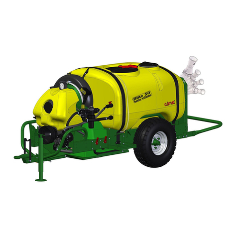
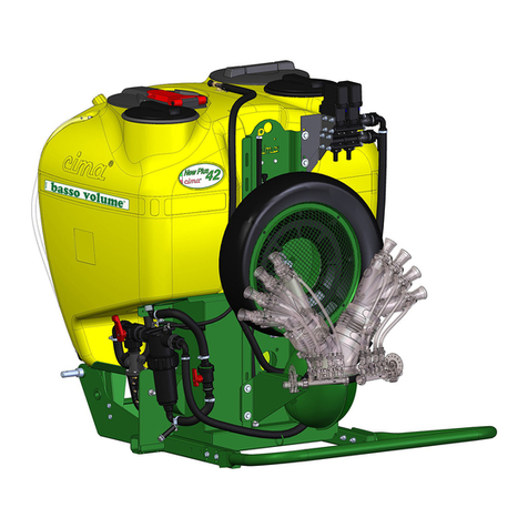
Cima P42 Troubleshooting guide

®
Atomizzatori e Impolveratori
OPERATION AND
MAINTENANCE INSTRUCTIONS
P42

Dear Customer, thank you very much!
We want to congratulate with you, for having
chosen a
®
sprayer.
Your choice shows the wisdom of the well-informed
Purchaser, aware of the fact, that the required
features of quality, technique and reliability must
be satisfied at the right price!
Our continuous engagement in R&D and in testing
our machines allows us to realize products able to
offer the best performances, a high reliability and
a great easiness of use at the same time !
Our first goal, is to get our Customers happy for
having met us!
The “Spare parts catalogue” of this sprayer/sprayhead is
available in the ‘“restricted area” on website www.cima.it.
In order to accede, use:
User name: sprayer
Password: 844719KE

LOW VOLUME MOUNTEDLOW VOLUME MOUNTED
LOW VOLUME MOUNTED
SPRAYERSPRAYER
SPRAYERSPRAYER
SPRAYER
Serial No.: ............................................................
INSTRUCTIONS FOR USEINSTRUCTIONS FOR USE
INSTRUCTIONS FOR USE
AND MAINTENANCEAND MAINTENANCE
AND MAINTENANCE
S.p.A.S.p.A.
S.p.A.S.p.A.
S.p.A.
27040 MONTU' BECCARIA - PV - ITALIA
Loc.Molino Quaroni - Tel. 0385/246636 r.a. - Fax 0385/246637
P 42 - P 45 - P 50P 42 - P 45 - P 50
P 42 - P 45 - P 50
P 55 - P 55SP 55 - P 55S
P 55 - P 55S

II
P 42 - P 45 - P 50 - P 55 - P55S - P55E 3-1999
LIST OF VALID PAGESLIST OF VALID PAGES
LIST OF VALID PAGES
This publication is composed of 64 pages divided in the following manner:
PAGE NO.PAGE NO.
PAGE NO.PAGE NO.
PAGE NO. REVISIONREVISION
REVISIONREVISION
REVISION ISSUE DATEISSUE DATE
ISSUE DATEISSUE DATE
ISSUE DATE
from I to IV 00 March 1995
from 1 to 60 02 March 1999
REGISTRATIONS OF ADDITI ONS AND CHANGESREGISTRATIONS OF ADDITI ONS AND CHANGES
REGISTRATIONS OF ADDITI ONS AND CHANGES
REVISIONREVISION
REVISIONREVISION
REVISION DESCRIPTIONDESCRIPTION
DESCRIPTIONDESCRIPTION
DESCRIPTION
00 Edition, March 1995
01 Edition, May 1996
02
03
04
05
06
07
08
Edition, March 1999

III
P 42 - P 45 - P 50 - P 55 -P55S - P55E 3-1999
TABLE OF CONTENTSTABLE OF CONTENTS
TABLE OF CONTENTS
11
11
1INTRODUCTIONINTRODUCTION
INTRODUCTIONINTRODUCTION
INTRODUCTION ......................................................................................................................................................................................................................................................
......................................................................................................................................................................................................................................................
........................................................................................................................... 11
11
1
1.1 PUBLICATION IDENTIFICATION .................................................................................................... 1
1.2 PUBLICATIONS ATTACHED ........................................................................................................... 1
1.3 PURPOSE OF THE PUBLICATION ................................................................................................. 1
1.4 REFERENCES TO REGULATIONS ................................................................................................ 1
1.5 USE OF THE MANUAL .................................................................................................................... 1
1.6 UPDATES ........................................................................................................................................ 2
22
22
2GLOSSARYGLOSSARY
GLOSSARYGLOSSARY
GLOSSARY ......................................................................................................................................................................................................................................................................
......................................................................................................................................................................................................................................................................
................................................................................................................................... 33
33
3
2.1 TERMINOLOGY ............................................................................................................................... 3
2.2 ABBREVIATIONS ............................................................................................................................ 3
2.3 SAFETY DECALS ............................................................................................................................ 3
33
33
3GENERAL INFORMATIONGENERAL INFORMATION
GENERAL INFORMATIONGENERAL INFORMATION
GENERAL INFORMATION ......................................................................................................................................................................................................................
......................................................................................................................................................................................................................
........................................................................................................... 77
77
7
3.1 IDENTIFICATION OF THE MACHINE ............................................................................................. 7
3.2 TECHNICAL ASSISTANCE ............................................................................................................. 7
3.3 SAFETY WARNINGS ....................................................................................................................... 7
3.4 SAFETY DEVICES ........................................................................................................................... 8
3.5 HANDLING OF AGROCHEMICAL PRODUCTS .............................................................................. 9
3.5.1 Storage............................................................................................................................................. 9
3.5.2 Specific equipment ........................................................................................................................... 9
3.5.3 Disposal of empty containers and agrochemical residue .................................................................. 9
3.5.4 Personal protection means ............................................................................................................. 10
44
44
4STRUCTURAL ANALYSIS OF THE MACHINESTRUCTURAL ANALYSIS OF THE MACHINE
STRUCTURAL ANALYSIS OF THE MACHINESTRUCTURAL ANALYSIS OF THE MACHINE
STRUCTURAL ANALYSIS OF THE MACHINE ......................................................................................................................................................
......................................................................................................................................................
........................................................................... 1111
1111
11
4.1 FRAME .......................................................................................................................................... 11
4.2 GEARBOX-FAN ............................................................................................................................. 12
4.3 HYDRAULIC CIRCUIT COMPONENTS......................................................................................... 13
4.4 TECHNICAL DATA ........................................................................................................................ 17
4.4.1 Machines dimensions and weights ................................................................................................. 17
4.4.2 Fan-pump functional characteristics ............................................................................................... 17
4.4.3 Fan technical characteristics .......................................................................................................... 18
55
55
5COUPLING MODECOUPLING MODE
COUPLING MODECOUPLING MODE
COUPLING MODE ............................................................................................................................................................................................................................................
............................................................................................................................................................................................................................................
...................................................................................................................... 1919
1919
19
5.1 TRACTOR HOOK-UP .................................................................................................................... 19
5.2 DRIVE JOINTS ASSEMBLY .......................................................................................................... 20
5.3 INSTALLATION OF REMOTE CONTROLS ................................................................................... 21
5.3.1 P7 - 2 cocks manual distributor ...................................................................................................... 21
5.3.2 E8 - Electric control unit.................................................................................................................. 21
66
66
6DISTRIBUTION DEVICESDISTRIBUTION DEVICES
DISTRIBUTION DEVICESDISTRIBUTION DEVICES
DISTRIBUTION DEVICES ......................................................................................................................................................................................................................
......................................................................................................................................................................................................................
........................................................................................................... 2323
2323
23
6.1 TYPES AND IDENTIFICATION CODES ........................................................................................ 23
6.2 ORIENTATION OF THE FAN-GUARD .......................................................................................... 24
6.3 ELBOW UNIONS FOR THE DISTRIBUTION DEVICES ................................................................ 24
77
77
7INSTALLATION OF THE ACCESSORIESINSTALLATION OF THE ACCESSORIES
INSTALLATION OF THE ACCESSORIESINSTALLATION OF THE ACCESSORIES
INSTALLATION OF THE ACCESSORIES ....................................................................................................................................................................
....................................................................................................................................................................
.................................................................................. 2525
2525
25
7.1 FILLING PIPING ............................................................................................................................ 25

IV
P 42 - P 45 - P 50 - P 55 - P55S - P55E 3-1999
7.2 COUPLE OF WHEELS .................................................................................................................. 25
7.3 CRANK CONTROLLED ROTOR ................................................................................................... 26
7.4 ROTATING GROUP WITH ELECTRIC CONTROL ....................................................................... 26
88
88
8FILLING PROCEDURESFILLING PROCEDURES
FILLING PROCEDURESFILLING PROCEDURES
FILLING PROCEDURES ..........................................................................................................................................................................................................................
..........................................................................................................................................................................................................................
............................................................................................................. 2727
2727
27
8.1 INTRODUCTION - USE OF THE FAN RELEASE .......................................................................... 27
8.2 BY INLET ....................................................................................................................................... 28
8.3 WITH FILLING PIPING .................................................................................................................. 29
99
99
9MIXTURE AGITATIONMIXTURE AGITATION
MIXTURE AGITATIONMIXTURE AGITATION
MIXTURE AGITATION ................................................................................................................................................................................................................................
................................................................................................................................................................................................................................
................................................................................................................ 3131
3131
31
1010
1010
10 DISCHARGE OF THE HYDRAULIC CIRCUITDISCHARGE OF THE HYDRAULIC CIRCUIT
DISCHARGE OF THE HYDRAULIC CIRCUITDISCHARGE OF THE HYDRAULIC CIRCUIT
DISCHARGE OF THE HYDRAULIC CIRCUIT ..........................................................................................................................................................
..........................................................................................................................................................
............................................................................. 3131
3131
31
1111
1111
11 SPRAYER ADJUSTMENTSPRAYER ADJUSTMENT
SPRAYER ADJUSTMENTSPRAYER ADJUSTMENT
SPRAYER ADJUSTMENT......................................................................................................................................................................................................................
......................................................................................................................................................................................................................
........................................................................................................... 3232
3232
32
11.1 BASIC INFORMATION: "LOW VOLUME" ...................................................................................... 32
11.2 DETERMINING THE ADJUSTMENT DATA ................................................................................... 35
1212
1212
12 PROCEDURES FOR USEPROCEDURES FOR USE
PROCEDURES FOR USEPROCEDURES FOR USE
PROCEDURES FOR USE ......................................................................................................................................................................................................................
......................................................................................................................................................................................................................
........................................................................................................... 4646
4646
46
12.1 OPERATIONS PRIOR TO TREATMENT ....................................................................................... 46
12.2 OPERATIONS IN PREPARATION FOR TREATMENT ................................................................. 46
12.3 TREATMENT ................................................................................................................................. 47
12.4 END OF TREATMENT - STORAGE .............................................................................................. 48
12.4.1 Daily ............................................................................................................................................... 48
12.4.2 End of seasonal cycle .................................................................................................................... 48
1313
1313
13 LIFTING AND TRANSPORTLIFTING AND TRANSPORT
LIFTING AND TRANSPORTLIFTING AND TRANSPORT
LIFTING AND TRANSPORT ..............................................................................................................................................................................................................
..............................................................................................................................................................................................................
....................................................................................................... 4949
4949
49
1414
1414
14 MAINTENANCE OPERATIONSMAINTENANCE OPERATIONS
MAINTENANCE OPERATIONSMAINTENANCE OPERATIONS
MAINTENANCE OPERATIONS ....................................................................................................................................................................................................
....................................................................................................................................................................................................
.................................................................................................. 5050
5050
50
14.1 LUBRICATION ............................................................................................................................... 50
14.2 CLEANING THE DELIVERY FILTER ............................................................................................. 51
14.3 CLEANING THE FAN (ONLY FOR P42E P45E P50E) .................................................................. 51
14.4 FAN BELT STRETCHER ............................................................................................................... 52
14.5 PUMP BELT STRETCHER ............................................................................................................ 52
14.6 TABLE OF MAINTENANCE OPERATIONS ................................................................................... 53
1515
1515
15 TROUBLE SHOOTINGTROUBLE SHOOTING
TROUBLE SHOOTINGTROUBLE SHOOTING
TROUBLE SHOOTING ................................................................................................................................................................................................................................
................................................................................................................................................................................................................................
................................................................................................................ 5454
5454
54
1616
1616
16 REPAIRS ALLOWEDREPAIRS ALLOWED
REPAIRS ALLOWEDREPAIRS ALLOWED
REPAIRS ALLOWED ....................................................................................................................................................................................................................................
....................................................................................................................................................................................................................................
.................................................................................................................. 5656
5656
56
16.1 ASSEMBLYING THE PUMP CONTROL BELT .............................................................................. 56
16.2 REPLACING THE FUSES OF THE ELECTRIC UNIT .................................................................... 56
1717
1717
17 INTEGRATIVE DIAGRAMSINTEGRATIVE DIAGRAMS
INTEGRATIVE DIAGRAMSINTEGRATIVE DIAGRAMS
INTEGRATIVE DIAGRAMS ..................................................................................................................................................................................................................
..................................................................................................................................................................................................................
......................................................................................................... 5757
5757
57
17.1 HYDRO-PNEUMATIC DIAGRAM .................................................................................................. 57
17.2 ELECTRIC CONNECTIONS .......................................................................................................... 58
1818
1818
18 NOISE LEVELNOISE LEVEL
NOISE LEVELNOISE LEVEL
NOISE LEVEL ..........................................................................................................................................................................................................................................................
..........................................................................................................................................................................................................................................................
............................................................................................................................. 5959
5959
59
1919
1919
19 GUARANTEEGUARANTEE
GUARANTEEGUARANTEE
GUARANTEE ............................................................................................................................................................................................................................................................
............................................................................................................................................................................................................................................................
.............................................................................................................................. 5959
5959
59
2020
2020
20 ENCLOSED: STATEMENT OF CONFORMITYENCLOSED: STATEMENT OF CONFORMITY
ENCLOSED: STATEMENT OF CONFORMITYENCLOSED: STATEMENT OF CONFORMITY
ENCLOSED: STATEMENT OF CONFORMITY ......................................................................................................................................................
......................................................................................................................................................
........................................................................... 6060
6060
60

1
P 42 - P 45 - P 50 - P 55 - P55S - P55E 3-1999
11
11
1INTRODUCTIONINTRODUCTION
INTRODUCTIONINTRODUCTION
INTRODUCTION 11
11
1
1.1 - PUBLICATION IDENTIFICATION1.1 - PUBLICATION IDENTIFICATION
1.1 - PUBLICATION IDENTIFICATION
The manual "INSTRUCTIONS FOR USE AND MAINTENANCE" is an official document issued by C.I.M.A. S.p.A. and
isconsidered an additionalpartofthe machine.The manual displaysa publicationnumber onthe thirdcoverpage which
allowsfor identification,tracing andreference.
All of the information contained herein has been accurately checked. C.I.M.A. S.p.A. reserves the right to modify this
manual without prior notice and does not take responsibility for any errors and/or omissions.
1.2 - PUBLICATIONS ATTACHED1.2 - PUBLICATIONS ATTACHED
1.2 - PUBLICATIONS ATTACHED
—Sparepartscatalogue;
—Instructions for use and maintenance of the distribution devices;
—Distributiondevices, Spare partscatalogue.
1.3 - PURPOSE OF THE PUBLICATION1.3 - PURPOSE OF THE PUBLICATION
1.3 - PURPOSE OF THE PUBLICATION
All of the necessary indications for use and maintenance contained in this manual are intended for the utilization of the
duster.The durationandfunctionality ofthe machine,the operator'ssafety and regardfor theenvironment alldepend on
thecareful observanceof theregulations describedherein.
Beforeusingtheduster,theoperator shouldreadandrespectallof the instructionslistedinthismanual, which areupdated
throughthe publicationdate.
1.4 - REFERENCE TO REGULATIONS1.4 - REFERENCE TO REGULATIONS
1.4 - REFERENCE TO REGULATIONS
This manual was created in conformity with the instructions contained in:
—Enclosure"I" of Instruction 89/392/C and subsequent modifications (letters"b", "c" of point 1.1.2 and point 1.7.4);
—UNI EN 292/2 - 1992, point 5.5.
1.5 - USE OF THE MANUAL1.5 - USE OF THE MANUAL
1.5 - USE OF THE MANUAL
Read this manual from the beginning to the end without omitting any pages, paying special attention totheRead this manual from the beginning to the end without omitting any pages, paying special attention tothe
Read this manual from the beginning to the end without omitting any pages, paying special attention tothe
meaningmeaning
meaningmeaning
meaning of the warning or danger instructions in the text and indicated by the signs displayed on the machineof the warning or danger instructions in the text and indicated by the signs displayed on the machine
of the warning or danger instructions in the text and indicated by the signs displayed on the machineof the warning or danger instructions in the text and indicated by the signs displayed on the machine
of the warning or danger instructions in the text and indicated by the signs displayed on the machine
or on its parts. All of the operations described herein should be carried out with the utmost care and only afteror on its parts. All of the operations described herein should be carried out with the utmost care and only after
or on its parts. All of the operations described herein should be carried out with the utmost care and only after
having understood the negative consequences of executing them poorlyhaving understood the negative consequences of executing them poorly
having understood the negative consequences of executing them poorly.
The manual is divided into two parts.The manual is divided into two parts.
The manual is divided into two parts.
∗The first, whose pages are marked with Roman numerals, consists in:
— Titlepage
— List of valid pages
— Registrationof additionsand changes
— Table of contents
Thisallowsforthe identificationofthepublication and awarenessofitslevel ofupdatingandvalidity regarding theproduct.
Thetableofcontents allows theusertofind thepagesconcerningthe subject he/sheisinterestedin quicklyandefficiently.

2
P 42 - P 45 - P 50 - P 55 - P55S - P55E 3-1999
* Thesecond part,whose pagesare markedwith cardinal numbers, has beendeveloped togive theuser thenecessary
informationforworkingwhile respectingthesafety standards duringallof the stagesofpreparation, use, handling and
maintenanceof theduster.
Inthe course ofthe text, we have used some symbolsto highlight andvisually distinguish theimportance of the different
kindsof information.
Graphicrepresentation andmeaning ofthe symbols:
Indicates important supplementary information.Indicates important supplementary information.
Indicates important supplementary information.
The non observance of the instruction given herein may cause damage to the atomizer which couldThe non observance of the instruction given herein may cause damage to the atomizer which could
The non observance of the instruction given herein may cause damage to the atomizer which could
be irreparable.be irreparable.
be irreparable.
Indicates possible situations of danger for persons.Indicates possible situations of danger for persons.
Indicates possible situations of danger for persons.
Themanual,itsenclosuresanditspossibleadditions,should be keptwiththeutmostcareandalwaysbecomplete,integral
andlegible in all of its parts. In case of loss,the owner must immediatelyask C.I.M.A. S.p.A. for a duplicate. If the decals
originallyplacedonthemachine should becomelost,damagedoreven partially incomprehensible,theymustbereplaced
withoutdelay.
Each type off head which can be used with the atomizer is delivered complete with a specific manual for use and
maintenance. Thisconstitutesanenclosuretothispublication.Alloftheheadmanualsmustalwayscomewiththemachine
manual.
--
--
-The manual should be kept for the entire life of the atomizer.The manual should be kept for the entire life of the atomizer.
The manual should be kept for the entire life of the atomizer.The manual should be kept for the entire life of the atomizer.
The manual should be kept for the entire life of the atomizer.
--
--
-All of the amendments received must be kept by inserting them in this publication.All of the amendments received must be kept by inserting them in this publication.
All of the amendments received must be kept by inserting them in this publication.All of the amendments received must be kept by inserting them in this publication.
All of the amendments received must be kept by inserting them in this publication.
--
--
-The manual should come with the atomizer when it is sold.The manual should come with the atomizer when it is sold.
The manual should come with the atomizer when it is sold.The manual should come with the atomizer when it is sold.
The manual should come with the atomizer when it is sold.
1.6 - UPDATES1.6 - UPDATES
1.6 - UPDATES
The possible updates that C.I.M.A. S.p.A. may send to the owner of the atomizer will be accompanied by the necessary
instructions for inserting them in this publication.
Ifthe machineis sold,the ownedmust askthe buyerto communicatehis/her address to C.I.M.A S.p.A., in order for them
to send the possible additions.

3
P 42 - P 45 - P 50 - P 55 - P55S - P55E 3-1999
22
22
2 GLOSSARY 2GLOSSARY 2
GLOSSARY 2GLOSSARY 2
GLOSSARY 2
2.1 - TERMINOLOGY2.1 - TERMINOLOGY
2.1 - TERMINOLOGY
Theterms FRONT,REAR,RIGHT andLEFT usedin this publicationare referred tothe atomizeras seen byan operator
standingbehindtheoperativeunitandlookingatthesame;therear partofthemachineisthenearestto the operator, where
the head is mounted; the front part is where the atomizer is hitched to the tractor.
The "distributing device" can also be called "distribution head".
2.2 - ABBREVIATIONS2.2 - ABBREVIATIONS
2.2 - ABBREVIATIONS
gg
gg
g...................................................................................................................................................................... grams
g/1'g/1'
g/1'g/1'
g/1' .......................................................................................................................................... revolutionsperminute
hh
hh
h........................................................................................................................................................................ hour
haha
haha
ha ................................................................................................................................................................ hectares
ha/hha/h
ha/hha/h
ha/h ............................................................................................................................................... hectaresper hour
ll
ll
l......................................................................................................................................................................... litres
l/hl/h
l/hl/h
l/h ........................................................................................................................................................ litres per hour
kgkg
kgkg
kg .............................................................................................................................................................. Kilograms
kmkm
kmkm
km ............................................................................................................................................................ Kilometers
km/hkm/h
km/hkm/h
km/h ........................................................................................................................................... Kilometersper hour
LmLm
LmLm
Lm ................................................................................................................................................... Width in metres
mm
mm
m.................................................................................................................................................................... metres
MeshMesh
MeshMesh
Mesh ........................................................................................................................ No. of meshes per straight inch
MicronMicron
MicronMicron
Micron ...................................................................................................................................... 1/1000 of millimeter
PTOPTO
PTOPTO
PTO ..................................................................................................................................................... powertake-off
ss
ss
s.................................................................................................................................................................. seconds
2.3 - SAFETY DECALS2.3 - SAFETY DECALS
2.3 - SAFETY DECALS
The machine is provided with decals concerning safety, use and maintenance.
SafetySafety
SafetySafety
Safety
11
11
1--
--
-9500195001
9500195001
95001 --
--
-STOP THE MOTOR AND TAKE THE KEY OUT OF THE TRACTOR CONTROL PANELSTOP THE MOTOR AND TAKE THE KEY OUT OF THE TRACTOR CONTROL PANEL
STOP THE MOTOR AND TAKE THE KEY OUT OF THE TRACTOR CONTROL PANELSTOP THE MOTOR AND TAKE THE KEY OUT OF THE TRACTOR CONTROL PANEL
STOP THE MOTOR AND TAKE THE KEY OUT OF THE TRACTOR CONTROL PANEL
BEFORE CARRYING OUT ANY MAINTENANCE OR REPAIR OPERATION.BEFORE CARRYING OUT ANY MAINTENANCE OR REPAIR OPERATION.
BEFORE CARRYING OUT ANY MAINTENANCE OR REPAIR OPERATION.
--
--
-Position: under the main tank, on the mobile protection.
22
22
2--
--
-9500495004
9500495004
95004 --
--
-DANGER: CONTAMINATION DUE TO CONTACT WITH OR INHALATION OF POISONOUSDANGER: CONTAMINATION DUE TO CONTACT WITH OR INHALATION OF POISONOUS
DANGER: CONTAMINATION DUE TO CONTACT WITH OR INHALATION OF POISONOUSDANGER: CONTAMINATION DUE TO CONTACT WITH OR INHALATION OF POISONOUS
DANGER: CONTAMINATION DUE TO CONTACT WITH OR INHALATION OF POISONOUS
PRODUCTS.PRODUCTS.
PRODUCTS.PRODUCTS.
PRODUCTS.
-Position: on the main tank, near the loading opening.
33
33
3--
--
-9500595005
9500595005
95005 --
--
-DANGER:ROTATING COMPONENTS.BEFORE REMOVING THE PROTECTIVE DEVICES,DANGER: ROTATING COMPONENTS. BEFOREREMOVING THEPROTECTIVE DEVICES,
DANGER:ROTATING COMPONENTS.BEFORE REMOVING THE PROTECTIVE DEVICES,DANGER: ROTATING COMPONENTS. BEFOREREMOVING THEPROTECTIVE DEVICES,
DANGER:ROTATING COMPONENTS.BEFORE REMOVING THE PROTECTIVE DEVICES,
STOP THE TRACTOR, TAKE THE KEY OUT OF THE CONTROL PANEL AND MAKE SURESTOP THE TRACTOR, TAKE THE KEY OUT OF THE CONTROL PANEL AND MAKE SURE
STOP THE TRACTOR, TAKE THE KEY OUT OF THE CONTROL PANEL AND MAKE SURE
THAT ALL COMPONENTS HAVE STOPPED.THAT ALL COMPONENTS HAVE STOPPED.
THAT ALL COMPONENTS HAVE STOPPED.
-Position:on the fan's guard, near the outlet opening.
44
44
4--
--
-9500895008
9500895008
95008 --
--
-THE MACHINE HAS NO ADDITIONAL HANDWASH TANK.THE MACHINE HAS NO ADDITIONAL HANDWASH TANK.
THE MACHINE HAS NO ADDITIONAL HANDWASH TANK.THE MACHINE HAS NO ADDITIONAL HANDWASH TANK.
THE MACHINE HAS NO ADDITIONAL HANDWASH TANK.
-Comparesotto ilserbatoio lavamani quando non èmontato.

4
P 42 - P 45 - P 50 - P 55 - P55S - P55E 3-1999
55
55
5--
--
-9501595015
9501595015
95015 --
--
-BEFORE USING THE RELEASE, STOP THE TRACTOR TAKE THE KEY OUT OF THEBEFORE USING THE RELEASE, STOP THE TRACTOR TAKE THE KEY OUT OF THE
BEFORE USING THE RELEASE, STOP THE TRACTOR TAKE THE KEY OUT OF THEBEFORE USING THE RELEASE, STOP THE TRACTOR TAKE THE KEY OUT OF THE
BEFORE USING THE RELEASE, STOP THE TRACTOR TAKE THE KEY OUT OF THE
CONTROL PANEL AND MAKE SURE THAT THE FAN HAS STOPPED.CONTROL PANEL AND MAKE SURE THAT THE FAN HAS STOPPED.
CONTROL PANEL AND MAKE SURE THAT THE FAN HAS STOPPED.
-Position: On the frame, near the manometer.
66
66
6--
--
- 9501095010
9501095010
95010 --
--
-MAXIMUM WORKING SPEED OF THE POWER TAKE-OFF: 540 RPM.MAXIMUM WORKING SPEED OF THE POWER TAKE-OFF: 540 RPM.
MAXIMUM WORKING SPEED OF THE POWER TAKE-OFF: 540 RPM.MAXIMUM WORKING SPEED OF THE POWER TAKE-OFF: 540 RPM.
MAXIMUM WORKING SPEED OF THE POWER TAKE-OFF: 540 RPM.
-Position: near the power take-off (PTO).
77
77
7--
--
-9500795007
9500795007
95007 --
--
-DANGER: SPRAYS. REMAIN AT A SAFE DISTANCE.DANGER: SPRAYS. REMAIN AT A SAFE DISTANCE.
DANGER: SPRAYS. REMAIN AT A SAFE DISTANCE.DANGER: SPRAYS. REMAIN AT A SAFE DISTANCE.
DANGER: SPRAYS. REMAIN AT A SAFE DISTANCE.
-Position: on the fan's guard.
88
88
8--
--
-9500695006
9500695006
95006 --
--
-ATTENTION: CONSULT THE USE AND MAINTENANCE MANUAL BEFORE USE OR WORKATTENTION: CONSULT THE USE AND MAINTENANCE MANUAL BEFORE USE OR WORK
ATTENTION: CONSULT THE USE AND MAINTENANCE MANUAL BEFORE USE OR WORKATTENTION: CONSULT THE USE AND MAINTENANCE MANUAL BEFORE USE OR WORK
ATTENTION: CONSULT THE USE AND MAINTENANCE MANUAL BEFORE USE OR WORK
ON THE MACHINE.ON THE MACHINE.
ON THE MACHINE.
--
--
-Position: up, right-hand side, on the machine front part.
99
99
9--
--
-9500995009
9500995009
95009 --
--
-DANGER: USE PROTECTIVE GLOVES WHEN DISCHARGING THE TANK.DANGER: USE PROTECTIVE GLOVES WHEN DISCHARGING THE TANK.
DANGER: USE PROTECTIVE GLOVES WHEN DISCHARGING THE TANK.DANGER: USE PROTECTIVE GLOVES WHEN DISCHARGING THE TANK.
DANGER: USE PROTECTIVE GLOVES WHEN DISCHARGING THE TANK.
-Position: on the frame , hight left-hand side , near the pump.
1010
1010
10 --
--
-9501295012
9501295012
95012 --
--
-DANGER: FIT THE WHEELS ONLY AFTER HOOKING THE MACHINE TO THE HOIST ANDDANGER: FIT THE WHEELS ONLY AFTER HOOKING THE MACHINE TO THE HOIST AND
DANGER: FIT THE WHEELS ONLY AFTER HOOKING THE MACHINE TO THE HOIST ANDDANGER: FIT THE WHEELS ONLY AFTER HOOKING THE MACHINE TO THE HOIST AND
DANGER: FIT THE WHEELS ONLY AFTER HOOKING THE MACHINE TO THE HOIST AND
REMOVE THEM A FTER RELEASING THE MACHINE FROM THE HOIST (ACCESSORY).REMOVE THEM A FTER RELEASING THE MACHINE FROM THE HOIST (ACCESSORY).
REMOVE THEM A FTER RELEASING THE MACHINE FROM THE HOIST (ACCESSORY).
-Position: on the frame, near the axle.
1111
1111
11 --
--
-9505995059
9505995059
95059 --
--
-HOOKING POINT FOR LIFTING THE MACHINE.HOOKING POINT FOR LIFTING THE MACHINE.
HOOKING POINT FOR LIFTING THE MACHINE.HOOKING POINT FOR LIFTING THE MACHINE.
HOOKING POINT FOR LIFTING THE MACHINE.
--
--
-Position: on the frame, over the fan's guard.
Use and maintenanceUse and maintenance
Use and maintenance
1212
1212
12 --
--
-9505295052
9505295052
95052 --
--
-GREASE EVERY 20 HOURS: FAN SHAFT BEARINGS.GREASE EVERY 20 HOURS: FAN SHAFT BEARINGS.
GREASE EVERY 20 HOURS: FAN SHAFT BEARINGS.GREASE EVERY 20 HOURS: FAN SHAFT BEARINGS.
GREASE EVERY 20 HOURS: FAN SHAFT BEARINGS.
-Position: on the frame, near the fan's guard, left-hand side.
1313
1313
13 --
--
-9505395053
9505395053
95053 --
--
-GREASE EVERY 50 H0URS: FAN BELT STRETCHER SUPPORT.GREASE EVERY 50 H0URS: FAN BELT STRETCHER SUPPORT.
GREASE EVERY 50 H0URS: FAN BELT STRETCHER SUPPORT.GREASE EVERY 50 H0URS: FAN BELT STRETCHER SUPPORT.
GREASE EVERY 50 H0URS: FAN BELT STRETCHER SUPPORT.
-Position: on the frame, near the fan's guard, right-hand side.
1414
1414
14 --
--
-9505495054
9505495054
95054 --
--
-GREASE EVERY 200 HOURS: FREE WHEEL.GREASE EVERY 200 HOURS: FREE WHEEL.
GREASE EVERY 200 HOURS: FREE WHEEL.GREASE EVERY 200 HOURS: FREE WHEEL.
GREASE EVERY 200 HOURS: FREE WHEEL.
-Position: on the front part, near the PTO protection guard.
1515
1515
15 --
--
-9506795067
9506795067
95067 --
--
-OIL EVERY 50 HOURS: PUMP BEARINGS.OIL EVERY 50 HOURS: PUMP BEARINGS.
OIL EVERY 50 HOURS: PUMP BEARINGS.OIL EVERY 50 HOURS: PUMP BEARINGS.
OIL EVERY 50 HOURS: PUMP BEARINGS.
-Position: on the left-hand side, near the pump.
1616
1616
16 --
--
-9505795057
9505795057
95057 --
--
-HANDWASH TANK COCK.HANDWASH TANK COCK.
HANDWASH TANK COCK.HANDWASH TANK COCK.
HANDWASH TANK COCK.
-Position:on thehand-wash tank.
1717
1717
17 --
--
-9506595065
9506595065
95065 --
--
-ATTENTION: NEVER LET THE ATOMIZER RUN WITHOUT LIQUID INSIDE THE TANK.ATTENTION: NEVER LET THE ATOMIZER RUN WITHOUT LIQUID INSIDE THE TANK.
ATTENTION: NEVER LET THE ATOMIZER RUN WITHOUT LIQUID INSIDE THE TANK.ATTENTION: NEVER LET THE ATOMIZER RUN WITHOUT LIQUID INSIDE THE TANK.
ATTENTION: NEVER LET THE ATOMIZER RUN WITHOUT LIQUID INSIDE THE TANK.
-Position: on the main tank, front side.
1818
1818
18 --
--
-9506395063
9506395063
95063 --
--
-INSTRUCTIONS FOR USE AND MAINTENANCE OF THE ELECTROVALVES.INSTRUCTIONS FOR USE AND MAINTENANCE OF THE ELECTROVALVES.
INSTRUCTIONS FOR USE AND MAINTENANCE OF THE ELECTROVALVES.INSTRUCTIONS FOR USE AND MAINTENANCE OF THE ELECTROVALVES.
INSTRUCTIONS FOR USE AND MAINTENANCE OF THE ELECTROVALVES.
-Position: on the tank, near the electric distributor.
1919
1919
19 --
--
-9506095060
9506095060
95060 --
--
-WHEEL OPERATING PRESSURE (ACCESSORY).WHEEL OPERATING PRESSURE (ACCESSORY).
WHEEL OPERATING PRESSURE (ACCESSORY).WHEEL OPERATING PRESSURE (ACCESSORY).
WHEEL OPERATING PRESSURE (ACCESSORY).
-Position:on thewheel.
2020
2020
20 --
--
-9507495074
9507495074
95074 --
--
-OPERATION OF THE THREE-WAY VALVE.OPERATION OF THE THREE-WAY VALVE.
OPERATION OF THE THREE-WAY VALVE.OPERATION OF THE THREE-WAY VALVE.
OPERATION OF THE THREE-WAY VALVE.
-Position: on the frame , low left-hand side, near the pump.
THE 5-FIGURE NUMBERS ARE THE CODES TO BE USED FOR ORDERING DECALS.THE 5-FIGURE NUMBERS ARE THE CODES TO BE USED FOR ORDERING DECALS.
THE 5-FIGURE NUMBERS ARE THE CODES TO BE USED FOR ORDERING DECALS.

5
P 42 - P 45 - P 50 - P 55 - P55S - P55E 3-1999
11 18
UMAP005a
UMAP097a
UMAP004
UMAP027
5
6
1
4
15
7
2
8
17
10
7
3
14
13
16 12
9
20
UNDER THE
HANDWASH
TANK
Positions of safety, use and maintenance decals

6
P 42 - P 45 - P 50 - P 55 - P55S - P55E 3-1999
12 95052
UMAP057
195001 295004
UMAP064
UMAP062
395005
UMAP060
495008 795007
UMAP058
UMAP055
595015 695010
UMAP066
895006
UMAP059
11 95059995009
UMAP056
10 95012
UMAP063
13 95053
UMAP046
14 95054
UMAP044
15 95067
UMAP045
UMAP047
16 95057 17 95065
UMAP068
18 95063
UMAP074
19 95060 20 95074
UMAP065
UMAP069 UMAP061
UMAP075b
∗∗
∗∗
∗SafetySafety
SafetySafety
Safety
∗∗
∗∗
∗Use and maintenanceUse and maintenance
Use and maintenanceUse and maintenance
Use and maintenance

7
P 42 - P 45 - P 50 - P 55 - P55S - P55E 3-1999
33
33
3GENERAL INFORMATIONGENERAL INFORMATION
GENERAL INFORMATIONGENERAL INFORMATION
GENERAL INFORMATION 33
33
3
3.1 - IDENTIFICATION OF THE MACHINE3.1 - IDENTIFICATION OF THE MACHINE
3.1 - IDENTIFICATION OF THE MACHINE
UMAP002
UMAP001
3.2 - TECHNICAL ASSISTANCE3.2 - TECHNICAL ASSISTANCE
3.2 - TECHNICAL ASSISTANCE
C.I.M.A. S.p.A. is at its customers' full disposal for any kind of assistance. The names and addresses of its assistance
centers, in Italy and abroad, may be requested at:
C.I.M.A. S.p.A.- Loc. Molino Quaroni - 27040 MONTU' BECCARIA (PV) - ITALIAC.I.M.A. S.p.A.- Loc. Molino Quaroni - 27040 MONTU' BECCARIA (PV) - ITALIA
C.I.M.A. S.p.A.- Loc. Molino Quaroni - 27040 MONTU' BECCARIA (PV) - ITALIA
tel. 0385-246636 - fax 0385-246637tel. 0385-246636 - fax 0385-246637
tel. 0385-246636 - fax 0385-246637
from abroad: 39-0385-246636- fax 39-0385-246637from abroad: 39-0385-246636- fax 39-0385-246637
from abroad: 39-0385-246636- fax 39-0385-246637
3.3 - SAFETY WARNINGS3.3 - SAFETY WARNINGS
3.3 - SAFETY WARNINGS
All of the preparation, use, maintenance, handling and transport operations should be carried out only after having
acquired perfect understanding of all instructions contained in this publication and the ability to interpret in the correct
way the symbols applied on the machine.
IT IS NOT PERMITTED TO USE THE DUSTER FOR PURPOSES OTHER THAN ITS ORIGINAL USE,IT IS NOT PERMITTED TO USE THE DUSTER FOR PURPOSES OTHER THAN ITS ORIGINAL USE,
IT IS NOT PERMITTED TO USE THE DUSTER FOR PURPOSES OTHER THAN ITS ORIGINAL USE,
AS IT HAS BEEN DEVELOPED EXCLUSIVELY FOR DISTRIBUTING INSECTICIDES ON AGRICULTU-AS IT HAS BEEN DEVELOPED EXCLUSIVELY FOR DISTRIBUTING INSECTICIDES ON AGRICULTU-
AS IT HAS BEEN DEVELOPED EXCLUSIVELY FOR DISTRIBUTING INSECTICIDES ON AGRICULTU-
RAL CULTIVATIONS.RAL CULTIVATIONS.
RAL CULTIVATIONS.
The following general rules must be respected scrupulously:
—always stop the motor before carrying out any operation on the atomizer;
—check that the weight and power of the tractor are compatible with the atomizer to be used;
—before use, check the different components of the machine for correct tightness and fastening, paying special
attention to the safety protection devices and the running parts;
—only use U-joints with protection devices accompanied by EC statement of conformity.
Carry out the coupling only if the power take-off of the tractor and atomizer is equipped with a counter guard;
—check that the protection device of the U-joint is fastened with the appropriate anti-rotation chains;
—clear people and animals away from the machine before starting it;
—do not wear clothes that could get caught in the running parts of the machine;
Identificationnameplate

8
P 42 - P 45 - P 50 - P 55 - P55S - P55E 3-1999
—reduce the speed when going over dips in the road or crossing ditches.
--
--
-All of the maintenance and repair operations should be carried out only after having carefullyAll of the maintenance and repair operations should be carried out only after having carefully
All of the maintenance and repair operations should be carried out only after having carefullyAll of the maintenance and repair operations should be carried out only after having carefully
All of the maintenance and repair operations should be carried out only after having carefully
cleaned the hydraulic circuit with clean water.cleaned the hydraulic circuit with clean water.
cleaned the hydraulic circuit with clean water.
--
--
-Before operating into the tank it is necessary to carefully wash it inside with clean water.Before operating into the tank it is necessary to carefully wash it inside with clean water.
Before operating into the tank it is necessary to carefully wash it inside with clean water.Before operating into the tank it is necessary to carefully wash it inside with clean water.
Before operating into the tank it is necessary to carefully wash it inside with clean water.
--
--
-It is forbidden to weld if ammonium salts have been used.It is forbidden to weld if ammonium salts have been used.
It is forbidden to weld if ammonium salts have been used.It is forbidden to weld if ammonium salts have been used.
It is forbidden to weld if ammonium salts have been used.
--
--
-It is forbidden to use the machine in a potentially explosive atmosphere.It is forbidden to use the machine in a potentially explosive atmosphere.
It is forbidden to use the machine in a potentially explosive atmosphere.It is forbidden to use the machine in a potentially explosive atmosphere.
It is forbidden to use the machine in a potentially explosive atmosphere.
--
--
-It is not permitted to spray paints and/or solvents, to wash areas and/or machinery or to utilize theIt is not permitted to spray paints and/or solvents, to wash areas and/or machinery or to utilize the
It is not permitted to spray paints and/or solvents, to wash areas and/or machinery or to utilize theIt is not permitted to spray paints and/or solvents, to wash areas and/or machinery or to utilize the
It is not permitted to spray paints and/or solvents, to wash areas and/or machinery or to utilize the
air stream for purposes different from the distribution of agrochemicals.air stream for purposes different from the distribution of agrochemicals.
air stream for purposes different from the distribution of agrochemicals.
3.4 - SAFETY DEVICES3.4 - SAFETY DEVICES
3.4 - SAFETY DEVICES
All running parts of the machine are adequately protected and indicated with warning decals.
--
--
-It is forbidden to use the machine if the protection devices have been removed.It is forbidden to use the machine if the protection devices have been removed.
It is forbidden to use the machine if the protection devices have been removed.It is forbidden to use the machine if the protection devices have been removed.
It is forbidden to use the machine if the protection devices have been removed.
--
--
-Before lifting the tank lid or removing the protection devices, stop the motor of the tractor and takeBefore lifting the tank lid or removing the protection devices, stop the motor of the tractor and take
Before lifting the tank lid or removing the protection devices, stop the motor of the tractor and takeBefore lifting the tank lid or removing the protection devices, stop the motor of the tractor and take
Before lifting the tank lid or removing the protection devices, stop the motor of the tractor and take
the key out of the control panel.the key out of the control panel.
the key out of the control panel.
The picture shows the protected parts of the machine:
UMAP022
MOVABLE PROTECTION
COVER
PTO PROTECTION
COUNTERGUARD
FAN'S PROTECTION
GRATE
UMAP093
UMAP071

9
P 42 - P 45 - P 50 - P 55 - P55S - P55E 3-1999
3.5 - HANDLING OF AGROCHEMICAL PRODUCTS3.5 - HANDLING OF AGROCHEMICAL PRODUCTS
3.5 - HANDLING OF AGROCHEMICAL PRODUCTS
The operatoroperator
operatoroperator
operator may be contaminated either by contact with or inhalation of the products and mixtures to be distributed.
The environmentenvironment
environmentenvironment
environment may be polluted by the spillage of the products, the careless conservation of empty or unwashed
packages, and by pouring the products into the water system.
To avoid these risks, the filling operations should be carried out in suitably prepared and adequately equipped areas, or
onthe treatment site.
3.5.3.5.
3.5.3.5.
3.5.11
11
1- Storage- Storage
- Storage- Storage
- Storage
Permanent/Stationary:Permanent/Stationary:
Permanent/Stationary:theroomusedshould be ventilatedandprovidedwithlockingdoors to preventtheaccidentalentry
of children and unskilled persons.
Mobile:Mobile:
Mobile:Mobile:
Mobile: thismeansofstorage shouldhavealock, to preventchildrenandunskilled personsfromopeningit intheabsence
ofthe operator.All containers, eitherfull orpartially used,must beplaced ina way soas notto tipover, fallor breakduring
transport.
Both types of storage should:
—have an appropriate container for storing the empty packages, if a special area is not available;
—have access to clean water for washing, by way of a container or connection to the water supply;
—have access to fire-extinguishers in the presence of inflammables.
--
--
-All containers, either full or partially used, should be kept in their original packaging and their labelsAll containers, either full or partially used, should be kept in their original packaging and their labels
All containers, either full or partially used, should be kept in their original packaging and their labelsAll containers, either full or partially used, should be kept in their original packaging and their labels
All containers, either full or partially used, should be kept in their original packaging and their labels
should always be legible.should always be legible.
should always be legible.
--
--
-The instructions for storage, use and disposal which are displayed on the original packaging of theThe instructions for storage, use and disposal which are displayed on the original packaging of the
The instructions for storage, use and disposal which are displayed on the original packaging of theThe instructions for storage, use and disposal which are displayed on the original packaging of the
The instructions for storage, use and disposal which are displayed on the original packaging of the
products should always be scrupulously respected.products should always be scrupulously respected.
products should always be scrupulously respected.
3.5.3.5.
3.5.3.5.
3.5.22
22
2- Specific equipment- Specific equipment
- Specific equipment- Specific equipment
- Specific equipment
The preparation or filling area must provide:
—allthe equipmentnecessary formeasuring the exact quantity of water andof theproduct tobe pouredinto the tank at
eachfilling;
—all the necessary equipment and tools for preparing the mixture and cleaning the operator in case of contamination;
—all equipment for the easy direct introduction of agrochemical products into the tank;
—asupplyofclothesand preventive measurestoavoidcontaminationeither by contactorinhalationduringthe operative
stageof theintervention;
—theappropriate equipment for stoppingspillage and pverflow of the mixture without control;
—a non-return valve on the supply pipe, when the tank is filled with water running directly from the water supply.
3.5.3.5.
3.5.3.5.
3.5.33
33
3- Disposal of empty containers and agrochemical residue- Disposal of empty containers and agrochemical residue
- Disposal of empty containers and agrochemical residue- Disposal of empty containers and agrochemical residue
- Disposal of empty containers and agrochemical residue
Agrochemicals are classified as "special" waste and their disposal must be different from "urban" waste.
The empty packages and the contaminated containers to be disposed of should not be abandoned,The empty packages and the contaminated containers to be disposed of should not be abandoned,
The empty packages and the contaminated containers to be disposed of should not be abandoned,
burnt or buried in the ground.burnt or buried in the ground.
burnt or buried in the ground.
The water used for washing the tanks and the equipment used for preparing the mixtures must not beThe water used for washing the tanks and the equipment used for preparing the mixtures must not be
The water used for washing the tanks and the equipment used for preparing the mixtures must not be
drained onto the ground or poured into channels, streams or rivers.drained onto the ground or poured into channels, streams or rivers.
drained onto the ground or poured into channels, streams or rivers.

10
P 42 - P 45 - P 50 - P 55 - P55S - P55E 3-1999
The disposal of special waste is regulated by specific norms.To carry out the operation, it is necessary to obtain the
appropriateinformationatthecompetentlocal offices. Thenon-observanceoftheselawsmay cause enormousdamages
topeople, animals andthe environment.
3.5.3.5.
3.5.3.5.
3.5.44
44
4- Personal protection means- Personal protection means
- Personal protection means- Personal protection means
- Personal protection means
Thetoxicityof agrochemicalscompelspeople usingthemto wearadequateprotective clothing andaccessoriesto avoid
the risks of contamination by contact or inhalation.
UMAP003
The operators must wear:The operators must wear:
The operators must wear:
—Polyethyleneorpolyvinylgloves.
—Full body overalls in waterproof cotton, to allow
perspiration with side polypropylene coatings. It is
possible to find disposable tyvek overalls that, after
use(seepicture),mustbedisposedofinthesameway
as the toxic waste.
—Half-size mask in neoprene rubber with 1 or 2 filters.
It is possible to use filters for gas and organic vapors
(European class A1) combined with filters against
powder (European class P1), for mists and irritating
powders,orP2formists and harmfulortoxicpowders.
The filters should be replaced:The filters should be replaced:
The filters should be replaced:
--
--
-when you notice odor/taste of agrochemicals, for class A1 with activated carbon;when you notice odor/taste of agrochemicals, for class A1 with activated carbon;
when you notice odor/taste of agrochemicals, for class A1 with activated carbon;when you notice odor/taste of agrochemicals, for class A1 with activated carbon;
when you notice odor/taste of agrochemicals, for class A1 with activated carbon;
--
--
-when you feel resistance in the breathing functions, for classes P1 and P2 against powders.when you feel resistance in the breathing functions, for classes P1 and P2 against powders.
when you feel resistance in the breathing functions, for classes P1 and P2 against powders.when you feel resistance in the breathing functions, for classes P1 and P2 against powders.
when you feel resistance in the breathing functions, for classes P1 and P2 against powders.
It is, however, necessary to use all personal protection means according to the recommendations of theIt is, however, necessary to use all personal protection means according to the recommendations of the
It is, however, necessary to use all personal protection means according to the recommendations of the
manufacturer.manufacturer.
manufacturer.

11
P 42 - P 45 - P 50 - P 55 - P55S - P55E 3-1999
HANDWASH
TANK
PUMP
LEVEL
INDICATOR
PRESSURE
VALVE
PRESSURE GAUGE
CENTRIFU-
GAL FAN
MAIN TANK MANUAL
DISTRIBUTOR
DISTRIBUTION
DEVICE
(HEAD)
ELBOW UNION
ROTATING
DISC
DISTRIBUTOR
FILLER
FRAME
PROTECTION BAR
The pictures show the position of the main components of the atomizerThe pictures show the position of the main components of the atomizer
The pictures show the position of the main components of the atomizer.
4.1 - FRAME4.1 - FRAME
4.1 - FRAME
The frames of the ranges P42 and P45The frames of the ranges P42 and P45
The frames of the ranges P42 and P45 may be coupled to hydraulic hoists of class "1""1"
"1""1"
"1".
The pins diameter is 22 mm. The pin of the top link is 19 mm dia.
The frames of the ranges P50, P55 and P55SThe frames of the ranges P50, P55 and P55S
The frames of the ranges P50, P55 and P55S may be coupled to hydraulic hoists of class "2""2"
"2""2"
"2".
The pins diameter is 28,5 mm. The pin of the top link is 25 mm dia.
Tolimitmoving thecenterof gravityandget afunctionalcoupling, allframesallow adoublepositioning ofthepins andtwo
possibilities of connecting the top link.
Framesareprepared forbeingfitted with aprotection bar forthedistribution devices;thisbar shallbemounted inthemost
efficient position, considering the work conditions and the type of heads employed.
A supporting bracket located in the frame front part, allows fitting the transmission joint when the machine is not couplet
to the tractor.
Under all frames there is an axle enabling fitting a couple of wheels, on request (see accessories installation, Par. 7.2).
4 STRUCTURAL ANALYSIS OF THE MACHINE4 STRUCTURAL ANALYSIS OF THE MACHINE
4 STRUCTURAL ANALYSIS OF THE MACHINE 44
44
4
UMAP004
UMAP005a
PISTON COCK
FILTER ON
DELIVERY
FAN HOUSING

12
P 42 - P 45 - P 50 - P 55 - P55S - P55E 3-1999
4.2 - FAN DRIVE4.2 - FAN DRIVE
4.2 - FAN DRIVE
Drive imput shaftDrive imput shaft
Drive imput shaft
BetweenthegearboxPtO andthefancontrol pulleythere
is a free wheel. In case of sudden decelerations or
unexpected motor stop, it permits the fan to continue its
free rotation thus avoiding the transmission of violent
stresses(seepicture) totheorgans involved inthemove-
ment.
Thepoly-V beltwhich transmitsthe motion to the fanand
the "V" belt of the centrifugal pump are equipped with
automaticbeltstretcherswhichmakemaintenanceunne-
cessary.
PTO COUPLING
POLY-V BELT
"V" BELT
AUTOMATIC BELT
TENSIONER
The front release device fitted to the fan shaft allows the running of the centrifugal pump, excluding that of the fan.
The fans' guards can turn by 360°. This allows locking the outlet opening in the exact point which is necessary for fitting
thevarious distribution devices.
Anair intakeon theguard outsidethe rim allows the pneumatic agitation ofthe mixture.It isconnected tothe cockabove
the tank by means of a pipe.
Centrifugal fan with closed blades, in steel sheet metal.
FAN
HOUSING
COLLAR
PUMP
LOWER
PULLEY
FREE WHEEL
DEVICE FOR RELEASING
THE FAN
NUT
AGITATOR AIR INTAKE
Centrifugal fanCentrifugal fan
Centrifugal fan
RELEASE
UMAP009A
UMAP051
UMAP010

13
P 42 - P 45 - P 50 - P 55 - P55S - P55E 3-1999
4.3 - HYDRAULIC CIRCUIT COMPONENTS4.3 - HYDRAULIC CIRCUIT COMPONENTS
4.3 - HYDRAULIC CIRCUIT COMPONENTS
T3
Tanks employed: 200 lt., fibreglass - 300, 400 and 600 lt., polyethylene.
Each tank is complete with:
—threadedtap, 355mm. diameter,with doublebreather valve;
—cup plastic filter: outside diameter 302 mm., height 254 mm.;
—two nylon bands with screw hooks for fixing it on the frame;
—externaltransparent pipe,level indicator,with graduatedscale onthe tank;
—hydraulic mixture agitator connecter to the return piping (T3);
HYDRAULIC AGITATOR
UMPA092
Hydraulicconnection diagram
P1
P6
T4
P7
P8
E7*
E8*
T5
DELIVERY DELIVERY
P5
T3
P4 T2
T6
P8
UMAP006a
P2
T1
T3
P3
FILLING PIPING
(ACCESSORY)
*For versions where it is
foreseen
ATTENTION:ATTENTION:
ATTENTION:
P and E = circuit partsP and E = circuit parts
P and E = circuit parts
T = pipingsT = pipings
T = pipings
* P1. TANK* P1. TANK
* P1. TANK
ADDITIONAL
HANDWASH TANK

14
P 42 - P 45 - P 50 - P 55 - P55S - P55E 3-1999
Riempimento
Scarico
Trattamento
P2
P4 P4
P3
P3
P4
=
P2
P2
UMAP075
From P1 tank the liquid arrives at P2 cock , through T1 pipeline ; it is sucked by the pump , sent to P4 with T2 hand
grip cock and sent again to the tank with T3 pipeline.
22
22
2UNLOADINGPOSITION.UNLOADINGPOSITION.
UNLOADINGPOSITION.UNLOADINGPOSITION.
UNLOADINGPOSITION.
The liquid of P1 tank arrives at P2 cock from T1 pipeline and P3 pump , through T2 , T3 pipelines and P4 hand grip
cock. Taking away P2 cock cap , it effects the unloading of the circuit.
33
33
3FILLING POSITION.FILLING POSITION.
FILLING POSITION.FILLING POSITION.
FILLING POSITION.
The liquid flow is interrupted from P1 tank to P3 pump.
T6
P3
UMAP049a
of a piping.
N.B.N.B.
N.B.N.B.
N.B. The tap is: aa
aa
a = open, cc
cc
c= closed
—additionalpolyethylene hand-washtank with screwcap andservice cock:18 litri
PNEUMATIC
AGITATOR
"cc
cc
c"
"aa
aa
a"
UMAP091
—pneumatic mixture agitator connected to the piston cock situated on the tank, and to the guard air inlet by means
••
••
•T1. SUCTION PIPINGT1. SUCTION PIPING
T1. SUCTION PIPINGT1. SUCTION PIPING
T1. SUCTION PIPING
It connects the tank with the P2 3-way valve , applied to the pump suction coupling.
••
••
•P2. LEVER THREE-WAYS COCKP2. LEVER THREE-WAYS COCK
P2. LEVER THREE-WAYS COCKP2. LEVER THREE-WAYS COCK
P2. LEVER THREE-WAYS COCK
Way of the liquid with the cock's lever in position:
11
11
1TREATMENTPOSITION.TREATMENTPOSITION.
TREATMENTPOSITION.TREATMENTPOSITION.
TREATMENTPOSITION.
Table of contents
Other Cima Paint Sprayer manuals