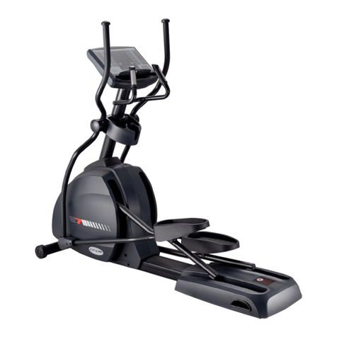
CIRCLE FITNESS E7 User manual


E7 –Owner’s Manual
Page2
TABLE OF CONTENTS
INTRODUCTION........................................................................................................................3
1. SAFETY.................................................................................................................................4
1. 1 Important Safety Notes_________________________________________________________________ 4
2. ASSEMBLY ...........................................................................................................................6
2.1 Specifications __________________________________________________________________________ 6
2.2 Machine Overview ______________________________________________________________________ 7
2.3 Location and Transportation ____________________________________________________________ 8
2.4 Unpacking _____________________________________________________________________________ 9
2.5 Assembly Procedures__________________________________________________________________ 12
2.6 Engineering Settings: Settings __________________________________________________________ 19
2.7 Test Operation ________________________________________________________________________ 20
3. OPERATION ........................................................................................................................ 21
3.1 Heart Rate System_____________________________________________________________________ 21
4. CONSOLE OVERVIEW ......................................................................................................... 22
4.1 Identifying the Parts of the Console _____________________________________________________ 22
4.2 Program Profiles and Operation ________________________________________________________ 24
5. ENGINEERING MODE.......................................................................................................... 33
5.1 ENGINEERING MODE 1: Settings________________________________________________________ 33
5.2 ENGINEERING MODE 2: TEST Mode_____________________________________________________ 34
6. MAINTENANCE................................................................................................................... 35
6.1 Preventive Maintenance Tips ___________________________________________________________ 35
6.2 Preventive Maintenance Schedule ______________________________________________________ 36
6.3 Error Message and Solutions ___________________________________________________________ 37
7. CUSTOMER SERVICE ......................................................................................................... 39
7.1 Warranty Claim Process________________________________________________________________ 39

E7 –Owner’s Manual
Page 3
INTRODUCTION
Dear Customer,
Thank you for purchasing this product.
This Owner’s Manual will guide you through the setup procedures and outline the key
features. Please keep it handy for future reference.
This product has been designed and manufactured for studio use, and even though we go
to great efforts to ensure the quality of each product, occasional errors, and/or omissions
do occur. In any event, should you find this product to be defective in any way, or to be
missing parts, please contact us.
No.12, 6th Road, Industrial Park,Taichung, Taiwan
Tel: +886-4-2359-1000
Fax: +886-4-3505-5801
Email: [email protected]
Website: http://www.circlefitness.com/

E7 –Owner’s Manual
Page4
1. SAFETY
1. 1 Important Safety Notes
IMPORTANT: Please read all instructions and warnings before assembly and operation.
To assure the correct use of the product, basic safety measures should always be
followed including the warnings and cautions listed in this Owner’s Manual.
IMPORTANT: It is essential that this equipment is used only indoors, in a climate
controlled room.
WARNING: Only one person at a time should use this equipment. If dizziness, nausea,
chest pains, or any other abnormal symptoms are experienced while using, then please
stop the workout at once.
WARNING: Always use this equipment on a clear and level surface. Do NOT use outdoors
or near water.
WARNING: Do NOT insert any object into any openings.
WARNING: Do NOT wear loose clothing or jewelry. This equipment contains moving parts.
Do NOT put fingers or other objects into the moving parts.
WARNING: Before using this equipment to exercise, always do stretching exercises first, in
order to properly warm up.
WARNING: It’s recommended to replace defective components immediately and keep the
equipment out of use until repairs have been made by a professional person.
WARNING: Keep children under age 14 and pets away from the equipment at all times.
WARNING: Please consult your physician before starting a workout or a training program.
Its best to have your doctor review your training and diet programs first so that he can
advise the best workout routine for you.
SAFETY SYMBOLS USED IN THIS OWNER’S MANUAL
WARNING
Indicates a potentially hazardous situation which, if not avoided, could
result in death or serious injury.
CAUTION
Indicates a potentially hazardous situation which, if not avoided, may
result in minor or moderate injury to the user or patient or damage to the
equipment or other property.
DANGER
Indicates a high probability that death, severe bodily injury or major
property damage could result.

E7 –Owner’s Manual
Page 5
1. 1 Important Safety Notes (Continued)
WARNING: Make sure all screws and nuts are securely tightened before operating this
equipment. Periodic maintenance is required on all exercise equipment to keep it in good
condition.
WARNING: Keep your back straight while using this equipment; do not arch your back.
WARNING: Incorrect/ excessive training can cause health injuries. Stop using the
equipment when feeling uncomfortable.
WARNING: The heart rate sensor is not a medical device. Various factors including the
user’s movement, may affect the accuracy of the heart rate readings. The heart rate
sensor is intended only as an exercise aid in determining heart rate trends in general.
WARNING: This equipment should not be used by person weighing more than 182 kgs
(400 lbs).
WARNING: Holding the handlebars or the upper body arms when mounting, dismounting
or using the equipment.
SAVE THESE INSTRUCTIONS FOR FUTURE REFERENCE

E7 –Owner’s Manual
Page6
2. ASSEMBLY
2.1 Specifications
Model : E7
Technical Specifications
Stride Length
500 mm/ 20 in
Pedal Spacing
64 mm/ 2.5 in
Step Up Height
320 mm/ 12 in
Resistance Level
25 Levels
Max. User Weight
182 kgs / 400 lbs
Features
Display Type
6 LED + 8 x 32 Dot-Matrix
Display Feedback
Time, Distance, Heart Rate, Watt, RPM, Level, METS
and Calories
Programs
Target, Rolling, Valley, Fat Burn, Ramp, Strength,
Interval, Random, Fitness Test and H.R.C
Hand Pulse
Standard
Heart Rate Receiver
Standard
Chest Belt
Optional
Electrical Specifications
Power Requirement
Self-Powered
Maximum Watt at 120 RPM
800
Minimum Watt at 40 RPM
20
Minimum RPM
10
Dimensions
Diameters (L x W x H) (approx.)
2040 x 680 x 1810 mm/ 81 x 27 x 72 in
Unit Weight (approx.)
105.6 kgs/ 232.3 lbs

E7 –Owner’s Manual
Page 7
2.2 Machine Overview
Bottle Holder
Upper Body Arm
Pedals
Console Set
Heart Rate Handlebar
Console Mast Cover
Transportation Wheel
Pedal Arm

E7 –Owner’s Manual
Page8
2.3 Location and Transportation
Location
Place the equipment on a level surface. Do NOT place it in any area that will block any
vents or air openings. This equipment should not be located in a garage, covered patio,
near water or outdoors.
Please leave a clear zone behind the equipment that is at least 24” (600 mm). This zone
must be clear of any obstruction and provide the user a clear exit path from the
equipment.
Fig 2.3-1
Transportation
To move the equipment, carefully lift the rear end by pushing down on the 2 front transport
wheels (Fig 2.3-2). Carefully steer the equipment to another location.
Fig 2.3-2
IMPORTANT: Be careful when moving this equipment, as it is heavy and awkward. If you
do not feel comfortable moving the unit by yourself, please get help.
NOTE: The transport wheels are designed for indoor use only and should not be used to
move the unit over rough surfaces such as concrete or asphalt.

E7 –Owner’s Manual
Page 9
2.4 Unpacking
To unpack the elliptical, please the following steps:
1. Carefully remove all staples from the carton.
2. Open the Carton 1 (Console) and remove the packing materials to take out the Console.
(Fig 2.4-1)
Fig 2.4-1
3. Open the Carton 2 and lift up the corner cardboard piece. (Fig 2.4-2)
Fig 2.4-2
3. Remove all parts from the Carton 2 and card board inserts.
4. Set the all the parts down near the spot where you plan to install the equipment.
5. With the help of at least one other person, remove all the packing materials and place
the main frame assembly on a level flat surface.
Carton 2
Carton 1

E7 –Owner’s Manual
Page10
2.4 Unpacking (Continued)
Please verify that you have parts as per the list shown below:
Carton 1
Carton 2
Carton 2
□
1Console Set
□
6Hardware Kit & Tools
(Refer to chapter 2.4.1 & 2.4.2)
□
2Upper Body Arm
□
3Console Mast Cover
□
4Right/ Left Pedal Arm Covers
□
5Main Frame
Carton 1

E7 –Owner’s Manual
Page 11
2.4.1 Hardware Kit
Please verify the hardware kit list as shown below:
2.4.2 Tools
Please verify the tools list as shown below:
STEP 6
(1) M4 x 12 mm Screws (8 PCS)
(2) M3 x 30 mm Screw (2 PCS)
(for Right/ Left pedal arm cover)
Allen Wrench (3mm)
Allen Wrench (6mm)
Allen Wrench (5mm)
Wrench
Lubricant
Owner’s Manual

E7 –Owner’s Manual
Page12
2.5 Assembly Procedures
STEP 1:
Move the Elliptical to Desired Location.
Carefully lift the rear end by pushing down on
the 2 front transport wheels (Fig 2.5-1).
Carefully steer the main frame to desired
location.
Fig 2.5-1
Required Tool
Required Parts/ Hardware Kit
N/A
N/A
STEP 2:
Attach the Console Mast Cover to the Upper Body Arm.
Attach the Console Mast Cover #1 to the
bottom of the Upper Body Arm #2. (Fig 2.5-2)
Fig 2.5-2
Required Tool
Required Parts/ Hardware Kit
N/A
Console Mast Cover (1 PC)
Upper Body
Arm #2
Console Mast
Cover #1

E7 –Owner’s Manual
Page 13
STEP 3:
Remove the Pre-installed Screws on the Main Frame.
Remove the pre-installed (2) M8 x 100 mm
Screws #1, (2) M8 x 110 mm Screws #2 and
(4) Washers #3 on the Main Frame with the
provided 6mm Allen Wrench. (Fig 2.5-3)
Fig 2.5-3
Required Tool
Required Parts/ Hardware Kit
Allen Wrench (6mm)
Allen Wrench (5mm)
Main Frame
M8 x 100 mm
Screw #1
M8 x 110 mm
Screws #2
Washers #3
Remove the pre-installed
screws & washers.

E7 –Owner’s Manual
Page14
STEP 4:
Console Wire Connection.
1) With the help of another person, lift the
upper body arm and position near the main
frame.
2) Thread the Guiding Wire #1 which is tied
with the Lower Console Wire #2 through
the Console Mast #3. (Fig 2.5-4A)
Fig 2.5-4A
3) Tie the Guiding Wire #1 on the top of
Console Mast #5. (Fig 2.5-4B)
WARNING: Ensure that the wires do not
become pinched or crushed as you lower
the console mast to the main frame.
Pinched or crushed wires will result in
shorting conditions and machine damage.
Fig 2.5-4B
Console Mast #3
Lower Console
Wire #2
Guiding
Wire #1
Guiding
Wire #1
Lower Console Wire #2
Guiding Wire #1
Lower Heart Rate Wires
Console Mast #3

E7 –Owner’s Manual
Page 15
STEP 4:
Console Wire Connection. (Continued)
5) Tighten (2) M8 x 110mm Screws and
Washers #6 with 6 mm Allen Wrench to fix
the Console Mast #5 on the Main Frame.
(Fig 2.5-4D)
6) Tighten (2) M8 x 110mm Screws and
Washers #7 with 6 mm Allen Wrench to fix
the Console Mast #5 on the Main Frame.
(Fig 2.5-4D)
Fig 2.5-4D
7) Snap the Console Mast Cover #8 in place.
(Fig 2.5-4E)
Fig 2.5-4E
Required Tool
Required Parts/ Hardware Kit
Allen Wrench (6mm)
Upper Body Arm with
Console Mast Cover
Main Frame
Console Mast #5
Console Mast
Cover #8
M8 x 110mm Screw
and Washer #6
M8 x 100mm
Screw and
Washer #7
M8 x 100mm Screw
and Washer #7
M8 x 110mm Screw
and Washer #6

E7 –Owner’s Manual
Page16
STEP 5:
Attach the Handle Arm to the Pedal Linkage.
1) Remove the Pre-Locked Screws And
Washers (#1, #2 and #3) from the Pedal
Linkage #4.
2) Attach the Pedal Linkage #4 to the Handle
Arm #5 and secure the Screws And
Washers (#1, #2 and #3) with provided
Allen Wrenches (6mm and 5mm).
3) Repeat Steps on the other side.
NOTE:
Pre-Locked Screw #1 is for M8 x 23 mm.
Pre-Locked Screw #2 is for M8 x 16 mm.
Pre-Locked Washer #3 is for M8.Fig 2.5-5
Required Tool
Required Parts/ Hardware Kit
Allen Wrench (6mm)
Allen Wrench (5mm)
N/A
Pedal Linkage #4
Handle
Arm #5
#1
#2 & #3
Handle
Arm #5
Pedal
Linkage #4

E7 –Owner’s Manual
Page 17
STEP 6:
Attach the Left/ Right Pedal Arm Covers on the Pedal Linkage.
1) Locate the Left Pedal Arm Covers #1 & #2
and align them over the Pedal Linkage #3
and press together so they snap in place.
2) Tighten (4) M4 x 12mm Screws #4 with a
5mm Allen Wrench.
3) Tighten (1) M3 x 30mm Screw #5 with a
3mm Allen Wrench.
4) Repeat Steps on the right side.
Fig 2.5-6
Required Tool
Required Parts/ Hardware Kit
Allen Wrench
(3mm)
Allen Wrench
(5mm)
M4 x 12 mm
Screws (8 PCS)
M3 x 30 mm
Screws (2 PCS)
Right/ Left
Pedal Arm
Covers
Left Pedal Arm Cover #1
Left Pedal Arm Cover #2
M3*30mm
Screw #5
Pedal Linkage #3
M4 x 12mm
Screws #4

E7 –Owner’s Manual
Page18
STEP 7:
Attach Console to Console Mast.
1) Unscrew the pre-locked screws on back of
the console.
2) Connect the Connectors (#1, #2, #3) from
the Console Mast #5 to the corresponding
connectors located in the Console Set.
(Fig 2.5-7A)
3) Remove the Guiding Wire #4. (Fig 2.5-7A)
Fig 2.5-7A
4) Fix the Console Set #5 to the Console
Mast #6 using the 4pcs M5 x 12mm
Screws #7 and the provided Allen wrench
(5mm). (Fig 2.5-7B)
Fig 2.5-7B
Required Tool
Required Parts/ Hardware Kit
Allen Wrench (5mm)
Console Set
Guiding
Wire #4
Connectors
(#1, #2, #3)
Console Set #5
Console Mast #6
M5 x 12mm
Screws #7

E7 –Owner’s Manual
Page 19
2.6 Engineering Settings: Settings
In IDLE mode, press STOP button then press FAST (
▲
)button for 3 seconds to enter
ENGINEERING MODE 1(Settings).
Language Selection:
Message window shows 【SET LANGUAGE】one time then shows『ENGLISH』.
Press▲or ▼button change to『NEDERLANDS』or 『FRANCAIS』or 『DEUTSCH』
or 『ITALIANO』or 『ESPANOL』or 『POLAND』, press ENTER button to next setting.
(This function is only for software version 1.03 or above.)
Software Version:
Message window shows【VER】, time
window shows software version, press
ENTER button to next setting.
Unit Setting:
Message window shows【SET UNIT】one time then shows【METRIC】, press ▲or ▼
button change to【ENGLISH】(Imperial), press ENTER button to next setting.
Total Used Distance:
Message window shows【ODO】,
DISTANCE & TIME window shows the total
used distance.
Total used distance= TIME window value +
(DISTANCE window value X 10000)
Press ENTER button to next setting.
Total Used Hours:
Message window shows【HRS】, TIME windows shows total hours value.
Press ENTER button to next setting.
Press ENTER button to return to
IDEL mode.
USB port is NOT
configured.
USB port is
configured.
SET Year, Month, Day, Hour, and
Minute.
Press ENTER button to return to
IDEL mode.
Machine Type Selection:
Message window shows【SET TYPE】,
Distance & Time show【E-7000】, press
ENTER button to next setting.
How to reset the Total Used Distance &
Total Used Hours:
If necessary, press and hold
RESET/CLEAR button and press ENTER
button for 5 seconds to reset the Total
Used Distance & Total Used Hours.
Other manuals for E7
6
Table of contents
Other CIRCLE FITNESS Elliptical Trainer manuals