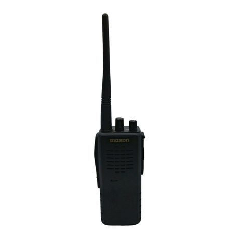
Maxon TSD-4000 Series User manual

TSD-4000 Series
Digital/Analog Radios
User’s Manual
Display
TSD-4424 (UHF)
TSD-4124 (VHF)
Non-Display
TSD-4416 (UHF)
TSD-4116 (VHF)

2
Table of Contents
1. Specs & Features --------------------------------------------------------------------------- 3
2. In-Box Contents & Series Accessories ------------------------------------------------ 4
3. Appearance of TSD-4424/4124 Series ------------------------------------------------- 5
4. Appearance of TSD-4416/4116 Series ------------------------------------------------- 6
5. Accessories and Charging ------------------------------------------------------------ 7
6. Basic Operating Instructions for TSD-4424/4124 Series ----------------------- 10
7. Basic Operating Instructions for TSD-4416/4116 Series ----------------------- 16
8. Precautions and Warranty Statement ----------------------------------------------- 17
Thank you for your purchase of the TSD-4000 Series radio.
1. Before using the radio, please read the user guide in detail.
2. The functions and specifications are subject to change without notice.

3
Specifications
TSD-4000 Series Radio Specifications
Frequency Range
Digital
Programmable Channels
Dimensions (H/W/D)
Weight w/battery
Power Source
Sensitivity
RF Power Output
TSD-4124/4116: 136 ~ 174 MHz
TSD-4424/4416: 400 ~ 470 MHz
DMR Tier II TDMA
512 Channels: 16 Channels with 32 Zones per channel
4.6 x 2.16 x 1.33” (118x55x34 mm)
234g
DC +7.4V Li-ion 2,600mAh Battery
0.25μV 12 dB SINAD (Analog)
0.22μV/BER 5% (Digital)
5/1 Watt (UHF & VHF)
Audio Power Output
Frequency Stability
Channel Spacing
Digital Vocoder
Dust and Water Protection
U.S. Military Standard
Operating Temperature
Storage Temperature
1 Watt
± 1.0 PPM (-30°to +60°C)
25/20/12.5 kHz (Analog) 12.5 kHz (Digital) 2 Time Slots of 6.25 Each
AMBE3000 Vocoder Chip with AMBE+2 Voice Compression Algorithm
IP-54
MIL-STD 810F/G
-30°C to +60°F
-40°C to +85°F
Features
AES Encryption (128, 192, 256)
Channel Tri-Mode (Digital, Analog, Mixed): compatible with the prevalent analog system,
ensuring a smooth analog-to-digital transition. Mixed mode allows your digital radio to
receive current analog radios yet transmit digitally to other DMR radios.
Long Battery Life: 17 hours (Analog) / 23 hours (Digital) on 90/5/5 duty cycle
Remote Stun / Revive
Remote Monitoring
CTCSS / DCS
VOX

4
2.In-Box Contents (Subject to change at buyer’s request)
Display or Non-Display Radio Battery Dual slot charger Antenna
DC Adapter Belt Clip User manual
Figure 2-1) TSD-4000 Series in-box items
Accessory Part Numbers:
ACC-440N: Radio Programming Software
ACC-3320E: Programming Cable (USB)
TSA-4260: 2,600mAH Li-ion battery pack
TSA-0400: Dual Slot Charger
TSA-041: VHF “Digital” antenna 6”
TSA-042: UHF “Digital” antenna 5¼”
TA-836X: Standard Speaker Microphone
TA-850X: Heavy Duty Speaker Microphone
TA-855X: Heavy Duty Speaker Microphone
w/volume control
TA-817X: “D” Style earpiece w/PTT
TA-818X: “Discrete” Style earpiece w/PTT
TA-819X: “C” Style earpiece w/PTT
TA-50LC/80LC (Display): Leather Carry Case
TA-50NC/80NC (Display): Nylon Carry Case
TSA-40BC: Spring Loaded Belt Clip

5
3. Controls and Appearance of TSD-4424/4124
Power ON/OFF Volume Control Knob
Turns radio on/off and adjusts audio volume level.
PTT Button (Push-To-Talk Button)
Press and hold the PTT button to transmit voice and
then release it to receive.
Menu/OK/Select (programmable button)
Used to make selections or enter menus. Long press
the button to get back to idle screen.
Menu Back/Power (programmable button)
Short press of the button will move you back one step
in a menu. Long press will toggle Tx power Hi / Lo.
Monitor Button
Default function of this button is to “Monitor” the open
channel. This button can be re-assigned through radio
programming.
Up/Down (programmable button)
Operates both as normal channel UP/DOWN button
when not in a menu and also as an UP/DOWN selector
when in a menu.
(SOS) Emergency Button & Flashlight
Short press will set off an emergency tone. Long press
of this button turns on/off the flashlight.
Status LED
This LED is a lamp indicating the current status of the
Radio and please refer to the below contents.
①RX : Green Lamp
②TX : Red Lamp
③CTCSS, DCS Error : Green Lamp blinks
④Low Battery: Red Lamp blinks with “beep” sound.
Speaker/MIC Jack
The accessory connector is used to connect an
external speaker microphone or headset. Keep cover
closed when not using accessories.
MIC
Please talk 2”from the mic hole for optimum clarity.

6
Figure 3-1) LCD Icons for TSD-4424/4124 DMR Radio
3.1 Controls and Appearance of TSD-4416/4116
Power ON/OFF Volume Knob
Turns radio on/off and adjusts audio volume level.
Channel Knob
Change channels by turning the control knob
clock-wise or counter-clockwise. 16 Channels can
be inputted into each zone. A voice response will
notify the user when the channel has been
changed. If the channel is not assigned, the radio
will beep.
PTT Button
Press the PTT button to transmit voice. Release
the PTTbutton to receive voice. It is recommended
to talk 2” to 4” away from the microphone.
P Button
Default function of this button is to easily toggle
between high transmit power and low transmit
power to save battery life. This button can be
reassigned through radio programming.
M Button
Default function of this button is to “Monitor” the
open channel. This button can be re-assigned
through radio programming.
TOP Button (Orange)
Default function of this button is “Emergency /
SOS”, This button can be assigned a different
function through radio programming.

7
Speaker/MIC Jack
The accessory connector is used to connect an
external speaker microphone or headset. Keep
cover closed when not using accessories.
Status LED
Used to determine Rx/Tx status and battery
charge level.
4. TSD-4000 Series: Accessories and Charging
Antenna Attachment and Removal:
Turn the antenna clockwise to put on and
tighten the antenna and then counterclockwise
to loosen and take off the antenna as shown in
diagram on right.

8
Battery Attachment and Removal:
Belt clip installation: Belt clip attaches to
the back of the radio above the battery. To
attach the belt clip, align the belt clip to the
grooves on the back of the radio as shown the
figure 4-2 and push it down (arrow). Clip will
“click” when locked.
Belt clip removal: To remove the belt clip,
push the belt clip locking tab in (direction 1) &
pull the belt clip up (direction 2) at the same
time.
Figure 4-2)
5. Charging the Battery
5.1 Safety Notes
1) TSD-4000 Series radios use a large capacity 2600 mAh Li-ion battery (TSA-4260). Use the
original battery and charger to ensure you are using safe and reliable equipment.
2) Please use a fully charged battery before using the radio for best performance and safety.
3) Please turn off the radio first to charge the battery.
5.2 When to Charge Your Battery
When your radio has low battery power, the distance it can communicate becomes shorter, and the

9
radio performance is degraded. These are the radio’s indicators to alert you to a low battery:
1) Red lamp on RX/TX LED blinks (every 0.5 second) during transmission or reception, and
LOW BATTERY beeping sound occurs during use.
2) Battery indicator icon is blinking.
5.3 How to Charge
1) Make sure power adapter for the Dual Slot charger is plugged into the charger (Figure 5-1) and
then plug the power adapter for the TSA-0400 charger into an AC120V power outlet.
2) Turn off the radio before charging.
3) Insert radio into the charger’s larger, front charging port with the charging contacts on the outside
of the radio lined up with the contacts on the charger. LED labeled “F” on the charger will turn on
when the connection is made.
4) If charging the battery only, line up the outside contacts of the battery with the charging contacts
on the 2nd, smaller charging slot in the rear of the dual charger and then insert the battery. LED
labeled “R” on the charger will turn on when the connection is made.
5) It is recommended to charge another 30 minutes after the LED turns green for a complete charge.
Status
LED indication
Charging
Red LED light
Charging Complete
Green LED light
Error Detected (Battery)
Red LED blinks
Battery in standby
Amber LED light
5.4 Charger (TSA-0400)
Figure 5-1) TSA-0400 and Adapter

10
6. Using the TSD-4424/4124 Display Series
6.1 Menu description
To enter the Menu mode, press the Menu / Select button. There are 8 main menus in Menu mode
when on a Digital Channel and 4 when on an Analog channel. These menus can be added or
removed via the radio’s PC programmer to help you organize the radio the way you want it. Navigate
left or right in this menu and select the menu you wish to go into with the menu button.
Figure 6-1) TSD-4424/4124 Digital Series Man Menu
Menu options will differ if radio is on a Digital Channel “Digital Mode” Fig 6-2) vs an Analog Channel
“Analog Mode” Fig 6-3), see below:
Figure 6-2) TSD-4424/4124 Digital Mode Main Menu tree

11
Figure 6-3) TSD-4424/4124 Analog Mode Main menu
☞Note) Radio will revert to standby mode if no selection made in 25 seconds.
6.1.1 Contact (Digital Mode Only)
You can enter your contact list through the settings menu. Radio IDs are set by the radio’s PC
programmer. Select the radio ID you want to contact and press the PTT button to make a call. Contact
lists in the menu can be added, edited, or deleted using the radio’s programming software.
The Contact Menu displays “Individual”, “Group”, and “All Call” contacts using the following icons:
- : Individual contact list (individual calls, individual messages can be sent)
Stun Radio, Revive Radio, Check Radio, & Monitor Radio functionality is
in this menu. “Stun” will disable the desired radio’s ability to Tx. “Revive” will
restore the functionality. “Check Radio” checks to see if the target radio in your
contact list is receiving. “Monitor Radio” turns on the mic of the target radio to
listen to the surrounding sound.
- : Group contact list (group call, group message can be sent)
- : All contact lists (terminals with the same channel and color code are available)
6.1.2 Messages (Digital Mode Only)
When a new message arrives and the radio is in receive mode, the message contents are displayed
on the display and the radio’s message menu appears. When a new message arrives during a
different radio operation, it will be displayed as a message icon.
The Message menu provides three additional menu functions: Quick Message, Inbox, and Outbox.
1) Quick Message
The radio holds 10 software programmable messages (each up to 40 characters) that the radio
sends via SMS in digital mode as a “Quick Message”. You get into the Quick Message menu
using your radio by entering the Main Menu and then select Messages. This will bring you to
the Messages menu. Select “Quick Text” to see the available messages to send. Highlight the
message you want to send and press the menu button to view the message contents. Press
the menu/select button again and highlight the recipient from your contacts list. Press select
button to select the recipient and send the message. Press and hold the select button to cancel,

12
or back up a step by pressing the “P” button.
2) Inbox
The message “Inbox” can hold a maximum of 10 received messages. View your inbox by
selecting “Inbox” from your Messages menu and then select the message you want to read
from the contents listed. After 10 messages are received in your inbox, the oldest message is
overwritten as a new message is received. You cannot delete a received message one at a
time. If you want to delete a message, you will need to select “Delete All” from the message
menu and delete all the messages in your inbox.
3) Outbox
The message “Outbox” holds a maximum of 10 sent messages. View your outbox by selecting
“Outbox” from your Messages menu and then select the message you want to read from the
contents listed. After 10 sent messages are stored in your outbox, the oldest message is
overwritten as a new message is created. You cannot delete a sent message one at a time. If
you want to delete a message, you will need to select “Delete All” from the message menu
and delete all the messages in your outbox.
6.1.3 Call Logs (Digital Mode Only)
Call Logs menu stores only the history of your individual calls. Group Calls and All Call radio calls
are not saved. The messages are managed by your Message Inbox and Outbox.
1) Inbox
Your radio can store 10 IDs of radios who have called you in your call history Inbox. If more
than 10 IDs are received, the oldest IDs are overwritten by the new ones. The Delete menu in
your inbox is used to delete your entire call history.
2) Outbox
Your radio can store 10 IDs of radios you have called in your call history Outbox. If more than
10 IDs are stored, the oldest IDs are overwritten by the new ones. The Delete menu in your
outbox is used to delete your entire call history.
6.1.4 Voice Record (Digital Mode Only)
You can record your incoming and outgoing radio calls with the “Voice Record” feature located in
the Main Menu when on a digital channel. Once it is turned ON, all incoming audio received through
the radio and every outgoing audio transmission will be recorded in separate files. Save up to 63,
2-minute transmissions. You have the ability to turn the feature ON or OFF in the Settings menu.
If you want to purposely remove a recording, you will need to “Delete All” messages. Numbering

13
for your oldest recordings start at #1 and are automatically deleted as new recordings are captured.
Both the transmitting and receiving radios must either have “Encryption Mode”
turned ON or OFF for Voice record calls. Voice record will not record
communications between one radio that is using encryption and one that is
not.
6.1.5 Scan (Digital Mode or Analog Mode)
When you turn on the Scan feature for your radio via the Scan menu off of the Main menu, scanning
will start in the order of the channels set in the scan list. If there is a radio channel being used during
scanning, the radio will stop on that channel and receive its contents. Use the radio programmer to
program and select the channel(s) you wish to transmit back on during the scan.
1) Scan ON/OFF –Used to turn Scan function ON or OFF in the Menu
2) Up to 10 scan lists can be setup using the programmer. Each list is selectable on the radio.
6.1.6 ZONE (Digital Mode or Analog Mode)
Zones are used to organize users within your channels and can be used to expand the number of
channels your radio can use. Your TSD-4000 Display series radio has 32 dynamic zones with a
maximum channel usage of 512. Contact your radio dealer to program your radio’s zones.
6.1.7 Settings
Radio Settings from the Main menu: Power Level (Tx), Voice Encryption, VOX, Lone Worker, BCL /
BCLO, Keypad Lock, Sound, Backlight, Brightness, LED settings, Language, Screen, Power Save.
1. Power Level
This setting gives you the ability to toggle your transmission power between High and Low.
High Power gives your radio a farther transmission range, but can drain your battery quicker.
Low Power saves battery life, but will shorten your transmission range.
2. Encryption (Digital Mode only)
Your radio’s Voice Encryption feature is used to encrypt incoming and outgoing voice
communications. Menu setting on radio turns encryption ON or OFF. Encryption settings are
adjustable using your radio dealer’s programming software. Encryption can be set for each
digital channel. Key length is up to 256 and key itself is created automatically according to
key length.
3. Squelch (Analog Only)

14
Suppresses channel noise when the radio is not receiving a transmission.
4. VOX
VOX function allows you to initiate a hand’s free voice-activated call through your radio when
you switch to a programmed channel or select it from the menu. The radio detects your voice
and automatically transmits without using the PTT button. The VOX feature’s sensitivity level
is adjustable by the radio’s programming software with level 5 being the least sensitive and 1
being the most sensitive.
5. Lone Worker (Digital Mode Only)
When turned on, the “Lone Worker” feature will automatically send out an emergency call to
the rest of your fleet through your radio when there is no radio activity within the time set in
the menu. To activate, select the time after you enter the Lone Worker menu by pressing the
up button. Each press will increment one minute. Choose between 1-100 minutes then press
the select button to make the selection. “Set Success” will appear on the screen when
activated.
6. BCL/BCLO
The BCL/BCLO function is used to prevent the radio from transmitting while the channel is
busy to avoid interruption of a conversation in progress. The default setting is OFF.
BCL (Busy Channel Lockout): Prohibits transmission on the same RF frequency.
BCLO (Busy Channel Lockout Override): Allows transmit only if the CTCSS/DCS or Color
Code match.
7. Keypad Lock
Keypad lock is used to lock the keypad from accidental keypresses. When the keypad lock
function is on, all buttons are locked except the PTT button, the emergency button and power
ON / OFF switch. If turned on from the Main Menu, the “Key Lock” feature is activated when
there is no input information for 5-20 seconds (programmable through settings menu). To turn
off “Key Lock”, long-press the P1 key to turn off the feature and use all the keys.
8. Tones
Allows you to turn on or off all tones in the radio.
9. Backlight
“On” keeps the radio’s backlight on indefinitely. “Timed” turns the backlight OFF after
a period of time set by your radio’s programmer.

15
10. Brightness
Used to adjust the screen brightness from 1 (dim) to 7 (brightest)
11. LED Control
Used to turn your LED status display ON or OFF. Your radio dealer can
adjust detailed LED status behavior using the radio’s programming software.
12. Language
Used to select the language for the radio’s menus. Korean or English.
13. Screen
Used to select between 3 different screen modes (see fig 5-1).
Figure 5-1) Description of Display screen selections
14. Power Save
Radio goes into power save mode until radio is activated. You can select
ratio on time radio checks for activity. Power save consists of 4 steps: ①OFF ②1: 1 ③
1: 2 ④1: 4.
6.1.8 Radio information
Used to show the radio’s information: Radio ID, Model Name, PCB Version, Freq Range, SW Version,
BB Number, BB Version Last SW Update, Made Date, DB Version. Press the “Select” button to make
a selection in this menu.

16
7. TSD-4416/4116 (Non-Display) Function and Operation
Function
Button & Setting
Status LED
Descriptions
Power
ON/OFF
ON/OFF/Volume
Control Knob
Orange
Power up chime is heard then current
radio channel selected will be spoken. If
radio is on an unprogrammed channel,
radio will beep. LED will be orange
during power up.
Transmit
(TX)
PTT Button
High Power: Red
Low Power: Orange
Press and HOLD PTT to talk, release to
listen. Other buttons can be
programmed with the PTT function
through your dealer’s software.
Receive
(RX)
Green
Steady green for decode. If channel is
busy, the LED blinks.
Channel
Change
Channel knob
Flashes Orange
during channel
switch
Turn the channel knob to the channel
you want. Voice will state what channel
you are on. If channel is not
programmed, radio will beep.
Adjust TX
Output
Power
(P) Button
*Programmable
Button
Orange
You can toggle between High Transmit
(TX) power and Low TX power by
pressing the “P” Button. Voice
announcement will indicate High or Low
Power setting.
Monitor
(M) Button
*Programmable
Button
Green w/ Voice
notification
User can check whether the Receive
Transmission (RX) of current channel is
OK or Not. Press and release the (M)
button to open the squelch on an
analog channel.
Emergency
Orange button on top.
*Programmable
Button
In an emergency, press the orange
colored Emergency button for 3
seconds to activate a siren & transmit
an emergency call to your party.
Switch Zone
PC programmable
function
Voice notification
Allows you to change the calling area to
use more channels
VOX
PC programmable
function
Voice notification
Used for transmitting voice without
pressing the PTT Button
SCAN
PC programmable
function
Voice notification
Scan button initiates the scan of each
channel in the scan list for activity. If
channel is busy, the radio stops scan
and received audio is heard. Scan
resumes when hang timer expires.
Normal & Priority Scan are available.
Stun/Revive
PC programmable
function
Voice notification
Used to disable and then revive radio
remotely via another radio
Encryption
(Digital Channel
Only)
PC programmable
function
Voice notification
Uses AES Encryption (128, 256) to
scramble & unscramble voice
transmissions for privacy.
Remote
Monitor
PC programmable
function
No indication on
target radio
Turns on radio’s microphone to monitor
any audible activity surrounding the
target radio.
Remote
Check
PC programmable
function
Voice notification
Checks whether target radio in your
contact list is receiving.
Talkaround /
Repeater
PC programmable
function
Voice notification
Switches the current channel from
repeater mode to talk-around mode and
visa-versa.
Keypad
Lock/Unlock
PC programmable
function
Voice notification
Locks and unlocks the keypad. This
feature prevents accidental key presses

17
8. Precautions
8.1 Precautions for Safe Operation of this equipment.
Don’t remove the antenna from the Radio and don’t transform the antenna or
make any changes to the antenna. Strong electronic waves emitted from the
Radio can have an effect on the performance of the Radio if the antenna is
modified and can cause the Radio to have a defect not covered under warranty.
Don’t use other manufacturer’s accessories (such as rechargeable battery,
Adapter, external speaker microphone and earphone, etc.). Unknown or
unauthorized accessories may damage the radio and void the warranty.
Don’t disassemble or reorganize the Radio. The disassembly or reorganization
of your radio is punishable by law and can cause damage to the radio that will
not be covered by the warranty
Don’t use frequencies you do not have a permit for.
Avoid excessive shock to the Radio. Don’t place the Radio where the direct
sunlight and/or the high temperature occurs, battery damage can occur in this
environment. Do not disassemble or damage the battery pack.
8.2 Do not use the radio where prohibited.
Your radio emits a strong electronic wave which may have an effect on the operation of other
equipment and can also be affected by those other devices.
Please turn off the Radio before boarding on airplane. If you want to use the
Radio in the airplane, please follow the rules in the airplane or the instructions
by crew.
If using radio in an area where medical equipment is being used, please get
permission from the related doctor to prevent interference issues.
Be careful when using your radio in a place where computers or other electronic
devices are being used because the strong electronic waves from the Radio can
affect this equipment.

18
8.3 Safety Notes
Please read the following recommendations for safe and effective use of the Radio.
• Please keep the Radio away at least 1 inch from the body.
• Do not touch antenna if it is damaged. Risk of skin burn can occur if the outside surface of antenna
gets stripped out.
• Please be careful when putting the battery in a pocket or a bag. If you contact a conductive metal
to a battery terminal, there is a heat and fire risk to your radio.
• Please don’t listen to the radio at a high-volume level when using earphones. Loud volume may
have a lasting bad effect on your hearing.
• It is recommended to adjust the volume step by step to the level you want after you set the radio
volume of the radio at a low level.
• Please don’t remove or replace or charge or discharge the battery in an hazard area where sparks
could cause an electrical fire.
• Turn off the radio in areas where there is a strong electromagnetic force.
FCC RF EXPOSURE COMPLIANCE REQUIREMENTS FOR OCCUPATIONAL USE ONLY
The Federal Communications Commission (FCC), with its action in General Docket 93-62, November 7, 1997, has adopted a
safety standard for human exposure to Radio Frequency (RF) electromagnetic energy emitted by FCC regulated equipment.
Proper operation of this radio will result in user exposure far below the Occupational Safety and Health Act (OSHA) and Federal
Communications Commission limits.
DO NOT transmit for more than 50% of total radio use time (50% duty cycle). Transmitting more than 50% of the time
can cause FCC RF exposure compliance requirements to be exceeded.
This radio is NOT approved for use by the general population in an uncontrolled environment. This radio is restricted
to occupational use, work related operations only where radio operator must have the knowledge to control the user’s
exposure conditions for satisfying the higher exposure limit allowed for occupational use.
When transmitting, hold the radio in a vertical position with its microphone 1 inches (2.5 cm) away from your mouth.
The radio is transmitting when the red LED on the front of the radio is illuminated. You can cause the radio to transmit
by pressing the PTT bar on the radio.
These are required operating configurations for meeting FCC RF exposure compliance. Failure to observe thes
e restrictions means violation.
This device complies with part 15 of FCC rules. Operation is subject to the following two conditions:(1)
This device may not cause harmful interference and (2) This device must accept any interference received,
including interference that may cause undesired operation.

19
Warranty Card
Thank you for purchasing a TSD-4000 Series radio.
1. This product has passed strict quality control and testing procedures
2. Warranty is one year from the date of manufacture.
• Failure of the product under normal operating conditions, during the warranty period
may be repaired by Maxon America free of charge.
3. For the following cases, service fees will be charged.
• When repair occurs after the warranty period has passed.
• When the product is damaged due to user’s mishandling, abuse or improper operation.
• When the product is damaged due to user’s modification, attempted repair or otherwise
access to sealed/non-user serviceable items.
• When the product is damaged due to fire, pollution, earthquakes and any other natural
or unnatural conditions, accidents, etc.
4. Personal information for radio:
Model No.
TSD-4000 Series
Serial No.
Purchase date
Purchaser
Name
Address
※Please contact Maxon below for Return Merchandise Authorization (RMA) number before
you send your radio back for service.
Maxon America
11535 West 83rd Terrace, Lenexa KS 66214
Tel: 800-456-2071
Fax: 913-859-9550

20
* This User manual is subject to change without notice.
Other manuals for TSD-4000 Series
1
This manual suits for next models
4
Table of contents
Other Maxon Radio manuals

Maxon
Maxon MDP-6000 Series User manual

Maxon
Maxon SP-510 User manual
Maxon
Maxon SP-120 Series User manual

Maxon
Maxon TJ-3000 Series User manual

Maxon
Maxon SD-270 Series User manual

Maxon
Maxon SM5402 User manual

Maxon
Maxon S1 PMR446 User manual

Maxon
Maxon SP-310 User manual

Maxon
Maxon PM160 User manual

Maxon
Maxon PM200 User manual

Maxon
Maxon SP-6102 User manual

Maxon
Maxon SP-0402 User manual

Maxon
Maxon MCB-10A User manual

Maxon
Maxon CM10 User manual
Maxon
Maxon SP-130 Series User manual

Maxon
Maxon SP210U2 User manual

Maxon
Maxon SD170EX Series User manual

Maxon
Maxon SM5102 User manual

Maxon
Maxon TM-4800 User manual

Maxon
Maxon SM-2000E Series User manual