Cisco TelePresence 3000 Instruction Manual

Americas Headquarters:
Cisco Systems, Inc., 170 West Tasman Drive, San Jose, CA 95134-1706 USA
Removing the Projector and Adding a
Presentation Display for Cisco TelePresence
3000 and 3200 Systems
February 1, 2012, OL-23393-01
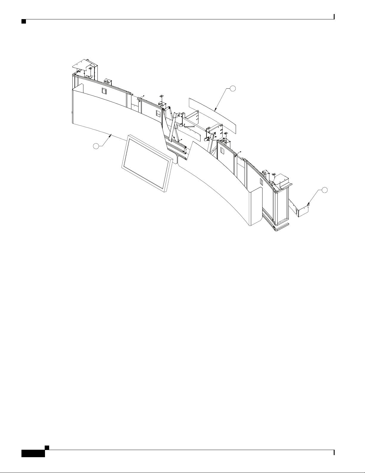
This document provides you with the procedures you perform to remove the projector from a
Cisco TelePresence 3000 or 3200 System and replace it with a display for external presentations.
This upgrade kit has the part number CTS-3X00-UPG and includes the following sections:
•Assembly Overview, page 2
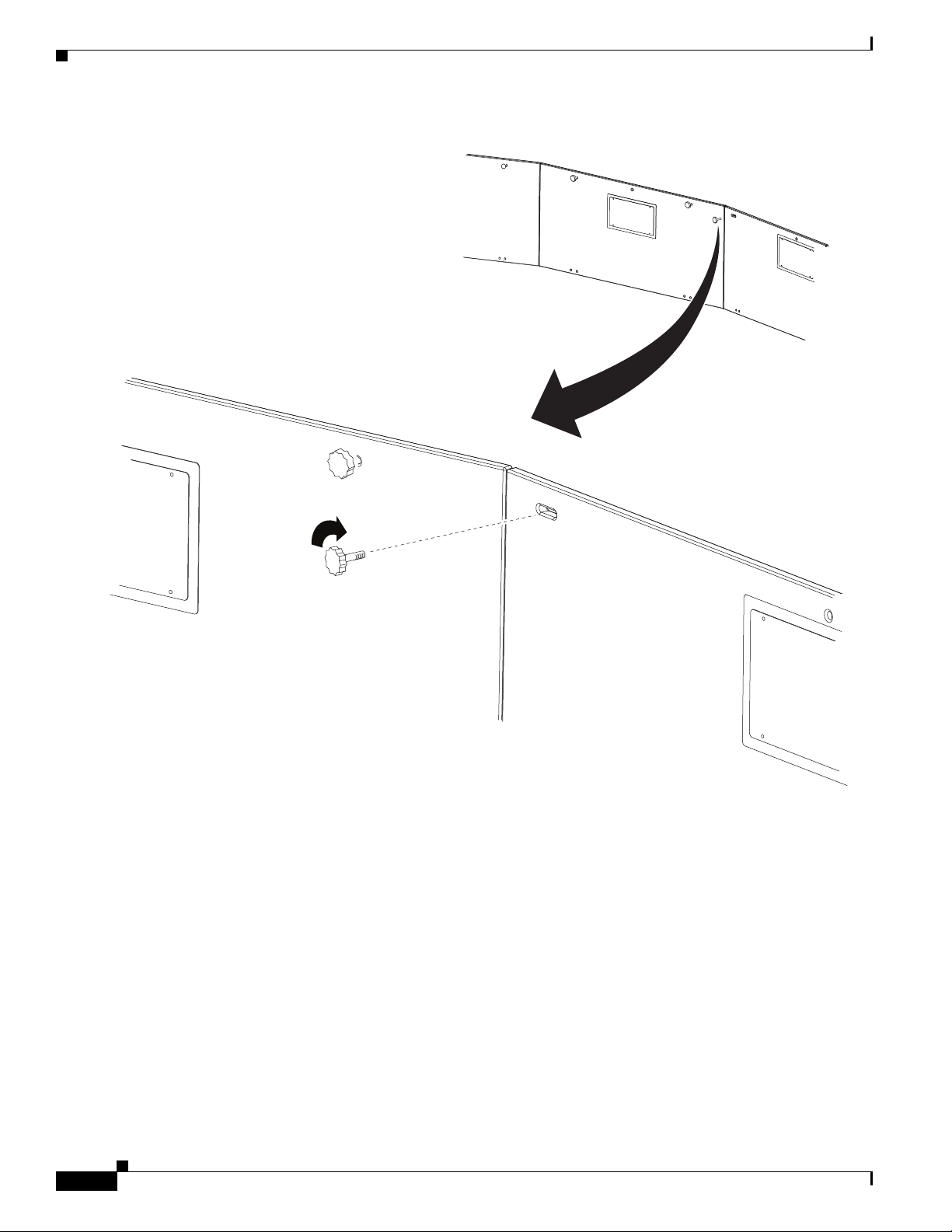
•Preparing for the Installation, page 2
•Unpacking, page 3
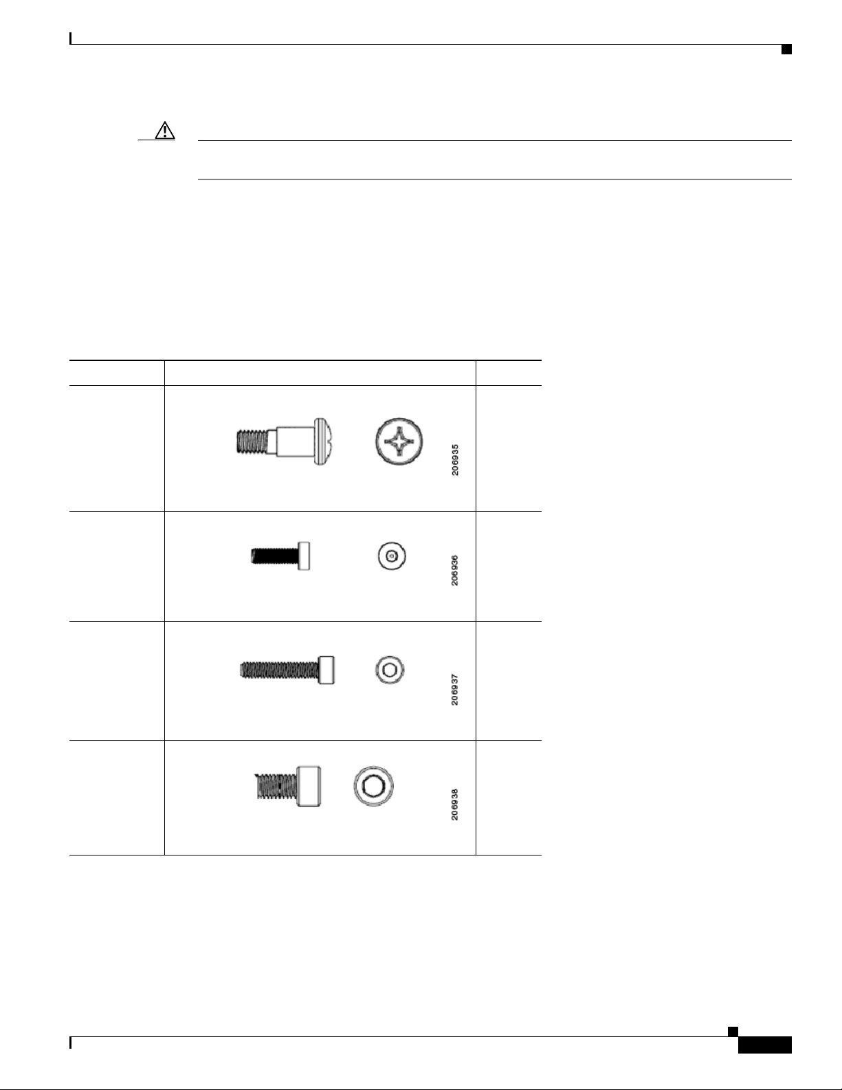
•Materials and Tools, page 3
•Preparing the Display Shelves for the Display and Screens, page 8
•Attaching the Screen and Shelf Attachment Hardware and Display Frame Brackets, page 12
•Removing the Projector and Installing the Privacy Panel Cover, page 22
•Preparing the Speakers, page 23
•Assembling the Screens, page 25
•Preparing the LCD Screen, page 42
•Attaching the Screen Assembly to the Cisco TelePresence System, page 44
•Completing the Assembly, page 48
•Troubleshooting the Display, page 51
•Cleaning Instructions, page 52
•LCD Display Cabling Diagrams, page 53

2
OL-23393-01
Assembly Overview
Perform the following steps to install the Cisco TelePresence Screen.
Step 1 Remove the speaker boards.
Step 2 Replace the frame brackets.
Step 3 Remove the projector and install the privacy panel cover.
Step 4 Assemble the kick guards.
Step 5 Prepare the speakers.
Step 6 Assemble the left frame.
Step 7 Attach the speaker cover.
Step 8 Attach the kick guard to the screen.
Step 9 Attach the speakers.
Step 10 Assemble the right screen following the same procedure as assembling the left screen.
Step 11 Prepare the LCD screen.
Step 12 Attach the screen assembly.
Step 13 Attach the sheath, LCD back cover, and PDUs.
Upgrade Kit Shipping Dimensions and Weight
The following section provides you with the shipping dimensions and weight of the upgrade kit.
Size of Entire Kit
48" x 48" x 45.5" (1220mm x 1220mm x 1156mm)
Weight of Entire Kit
222 pounds (83Kg)
Size of Kit Components
Facade (includes speaker covers): 45.75” x 17.75” x 41” (1162mm x 451mm x 1041mm)
40-inch high definition display: 42.25” x 12” x 27.75” (1073mm x 305mm x 705mm)
Speakers: 23” x 22.25” x 12.625” (584mm x 565mm x 321mm)
Remaining system components: 24.25” x 20.125” x 14.75” (616mm x 511mm x 375mm)
Preparing for the Installation
Some assembly tasks require two people to complete. Assembling the screen requires a dirt- and
debris-free area of at least 9 feet by 5 feet (2.7 meters by 1.5 meters). You should assemble the screen
on top of a soft area such as carpet or foam to prevent any damage to the parts. The area should be clear
of any dirt or debris before you begin assembling.

3
OL-23393-01
Unpacking
Your frame is shipped with the necessary materials to install the screen. Carefully unpack and make sure
you have all of the items shown in the inventory list presented in the Material & Tool Contents section.
Materials and Tools
The materials and tools in Table 1 are provided in the installation package. Use the following table to
make sure you have all the necessary materials and tools.
Table 1 Materials and Tools for Part Number CTS-3X00-UPG
Item No. Description Qty Yes No Part Number
1 Left Center Sub-Assembly 1 Part of CTS-3X10FACADE
2 Right Center Sub-Assembly 1 Part of CTS-3X10FACADE
3 Left Sub-Assembly 1 Part of CTS-3X10FACADE
4 Kick guard Center Tube with no Frame Guide Sub-Assembly 1 Part of CTS-3X10FACADE
5 Kick guard Center Tube Sub-Assembly 1 Part of CTS-3X10FACADE
6 Left-Right kick guard Sub-Assembly 2 Part of CTS-3X10FACADE
7 Right Sub-Assembly 2 Part of CTS-3X10FACADE
8 Speaker Locating Bracket 4 Part of CTS-3X10FACADE
9 Locating Plate 4 Part of CTS-3X10FACADE
10 Left End Unit Cap 1 Part of CTS-3X10FACADE
11 Right End Unit Cap 1 Part of CTS-3X10FACADE
12 Left LCD Mounting Bracket 1 Part of CTS-3X10FACADE
13 Right LCD Mounting Bracket 1 Part of CTS-3X10FACADE
14 Hanger Rod 1 Part of CTS-3X10FACADE
15 Holding Bracket 1 Part of CTS-3X10FACADE
16 Left Angle Bracket Sub-Assembly 1 Part of CTS-3X10FACADE
17 Right Angle Bracket Sub-Assembly 1 Part of CTS-3X10FACADE
18 M6 Shoulder Screw (see Table 2) 16 Part of CTS-3X10FACADE
19 M4 x 12 Low Head SHCS (see Table 2) 28 Part of CTS-3X10FACADE
20 M4 x 20 SHCS (see Table 2) 18 Part of CTS-3X10FACADE

4
OL-23393-01
21 M6 x 10 SHCS (see Table 2) 4 Part of CTS-3X10FACADE
22 M6 x 16 Pan Head Phillip Screw (see Table 2) 2 Part of CTS-3X10FACADE
23 M8 x 16 Pan Head Phillip Screw (see Table 2) 4 Part of CTS-3X10FACADE
24 White Front Cover 2 Part of CTS-3X10FACADE
25 LCD Back Cover 1 Part of CTS-3X10FACADE
26 Foot Bracket Sub-Assembly 6 Part of CTS-3X10FACADE
27 Kick Guard Skirt 2 Part of CTS-3X10FACADE
28 Washer 2 Part of CTS-3X10FACADE
29 Open Ended Wrench 1 Part of CTS-3X10FACADE
30 2.5 mm T-handle Allen wrench 1 Part of CTS-3X10FACADE
31 5 mm Allen wrench 1 Part of CTS-3X10FACADE
32 3 mm Long-Arm Allen wrench 1 Part of CTS-3X10FACADE
33 Gloves 2
pairs
Part of CTS-3X10FACADE
34 Left Frame Bracket 2 Part of CTS-3X10FACADE
35 Right Frame Bracket 2 Part of CTS-3X10FACADE
36 Left Center Frame Bracket Assembly 1 Part of CTS-3X10FACADE
37 Right Center Frame Bracket Assembly 1 Part of CTS-3X10FACADE
38 Privacy Panel Cover 1 Part of CTS-3X10FACADE
39 Cable Sheath 1 Part of CTS-3X10FACADE
40 Self Tapping Screw 1 Part of CTS-3X10FACADE
41 Foam Sheet 1 Part of CTS-3X10FACADE
42 LCD Screen 1 CTS-DATA-DISP-40
43 HD Video cable 1 Part of CTS-3X10FACADE
44 Speaker 4 CTS-LDSPKR-G3
45 Speaker cable 4 Part of CTS-3X10FACADE
46 M8 screw Part of CTS-3X10FACADE
Table 1 Materials and Tools (Continued)for Part Number CTS-3X00-UPG
Item No. Description Qty Yes No Part Number

5
OL-23393-01
Caution Do not use power tools during the assembly of the frames and screens. The use of power tools may
permanently damage the screen. The installation kit provides all the tools required to assemble the screen
The following tools are required for removal of the projector, removal and reinstallation of the display
shelf and installation of the LCD screen brackets:
•Power drill
•Phillips drill bit
To differentiate between the different screws that are used in this installation, see Table 2. The
illustrations in the table are close to the actual size of the screws.
Table 2 Fasteners Used in Installation Procedure
Item Number Image and Description Quantity
18
M6 Shoulder Screw
16
19
M4 x 12 Low Head SHCS
28
20
M4 x 20 SHCS
18
21
M6 x 10 SHCS
4

6
OL-23393-01
After you unpack the materials and identify all the parts, you are ready to set up the screen. Refer to
Figure 1 and Figure 2 to assist you in assembling the Cisco TelePresence Screen. Each illustration is
keyed numerically to the Materials and Tools list. You can refer to the Materials and Tools list to identify
the specific screw or bracket being used in an illustration.
22
M6 x 16 Pan Head Phillip Screw
2
23
M8 x 16 Pan Head Phillip Screw
4
Table 2 Fasteners Used in Installation Procedure (Continued)
Item Number Image and Description Quantity

7
OL-23393-01
Figure 1 Exploded View of Screen Frame Components
8
23
12
13
4
5
6
10
3
15
2
9
22
14
19
7
20
1
17
18
21
11
16
27
206941

8
OL-23393-01
Figure 2 Exploded View of Screen Components With LCD Display
Preparing the Display Shelves for the Display and Screens
This section provides you with the procedures you prepare the Cisco TelePresence system for the new
display and screens and includes the following topics:
•Removing the Existing Screen and Speaker Boards, page 8
•Attaching the Screen and Shelf Attachment Hardware and Display Frame Brackets, page 12
Removing the Existing Screen and Speaker Boards
This section provides you with the procedure you complete to remove the screen and speaker boards and
includes the following topics:
•Required Parts and Tools, page 9
•Removing the Existing Screen and Speaker Boards, page 9
24
25
26
206942

9
OL-23393-01
Required Parts and Tools
The following tools are required to remove the screen and speaker boards:
•#2 Phillips screwdriver#
Note This installation kit does not provide the tools needed to prepare the display shelves. The M8 screws
needed to prepare the display shelves come with the accessory kit for the display shelf assembly.
Removing the Existing Screen and Speaker Boards
Complete the following procedure to remove the existing screen and speaker boards.
To remove the speaker boards, complete the following steps.
Step 1 Power off the Power Distribution Units (PDU).
Step 2 Determine the type of screen you have and complete one of the following steps depending on the screen
type:
•If the screen has a black strip (kick guard) on the bottom of the screen, complete the following steps:
1. Lower the feet that are at the bottom of the screen to their lowest height by rotating them counter
clockwise with the open ended wrench.
2. Pull the screen out and away from the display shelves.
Figure 3 Lowering the Screen Feet For a Screen With a Kick Guard
•If the screen does not have a kick guard on the bottom of the screen and is completely white, detach
the screen from the clips on the perimeter around the screen and pull the screen out and away from
the display shelves.
Note Store the screen away from the Cisco TelePresence setup.
Step 3 Remove the quarter-turn screws or knobs that attach the left speaker board to the display frame, then
remove the left speaker board.
Note To remove the speaker boards that have quarter-turn screws, unscrew the screws one-quarter turn so that
they fit through the slots in the speaker boards. To remove the speaker boards that have knobs, unscrew
the knobs.
206943

10
OL-23393-01
Figure 4 Removing the Speaker Boards
207169

11
OL-23393-01
Step 4 Pull the speaker board out approximately six inches (15 cm).
Step 5 Loosen the screws that attach the spade terminals and speaker cable to the speakers, then remove the
cables from the speaker.
Step 6 Remove the speaker board.
Step 7 Repeat Step 3 through Step 7 to remove the center and right speaker boards and speakers.
Step 8 Remove all speaker board brackets and either the screen clips or locating plate for the screen.
The top illustration in Figure 5 shows the speaker board brackets. The lower illustration shows the clip
and the locating plate; remove either the clip or the plate, depending on your system.
Note Make a note of the hole location for the clips or plates; you use these same holes to install the new plates
in Step 4 of the “Attaching the Screen and Shelf Attachment Hardware and Display Frame Brackets”
section on page 12.
Figure 5 Speaker Board Bracket
206945

12
OL-23393-01
Attaching the Screen and Shelf Attachment Hardware and Display Frame
Brackets
This section describes the steps you perform to replace the diamond-shaped locating plate, screen
locating plate, and frame brackets, and includes the following topics:
•Required Parts and Tools, page 12
•Replacing the Frame Brackets, page 12
Required Parts and Tools
•#2 Phillips screwdriver
•4 locating plates
•2 left frame brackets
•2 right frame brackets
•1 left center frame bracket
•1 right center frame bracket
•1 hanger rod
•2 washers
•M8 screws
•2 M6 x 16 screws
Replacing the Frame Brackets
To replace the frame brackets, complete the following steps.
Step 1 Make sure the PDU(s) are powered off.

13
OL-23393-01
Step 2 Remove the PDUs, left and right cabinets, and cabinet brackets by completing the following steps:
a. Remove the PDUs from the cabinets and set them aside.
a. Rotate the cabinet feet clockwise to lower the feet.
b. Remove the screws that attach the cabinet to the display shelf.
c. Slide the cabinet away from the Cisco TelePresence system.
d. Remove the cabinet brackets from the underside of the display shelves.
Figure 6 Removing the Cabinets
207168

14
OL-23393-01
Step 3 Attach the diamond-shaped shelf bracket to the right side of the table.
This bracket joins the right display shelf and the right-wing tabletop section.
Figure 7 Attaching the Shelf Bracket to the Display Shelves
206946
20

15
OL-23393-01
Step 4 Attach the new locating plates to the underside of the display shelf.
Use the same attachment holes as the locating plates or screen clips that you removed during Step 8 in
the “Removing the Existing Screen and Speaker Boards” section on page 8
Note Attach the locating plates so that the locating pin faces the rear of the system as shown in Figure 8.
Figure 8 Locating Plate Orientation
206947

17
OL-23393-01
Step 6 Remove the frame bracket from the left display shelf.
Warning
Remove and replace only one frame bracket at a time. The frame brackets support the plasma screen.
If you remove both frame brackets under one display shelf, the shelf and plasma screen will be
unstable and may fall.
Tip You can remove either the left or right bracket first. Figure 10 shows the right bracket being removed.
Figure 10 Removing the Frame Bracket
Step 7 Attach the new frame bracket underneath the left display shelf.
You might have to raise or lower the plasma display leveling feet to make sure that the display remains
firmly seated on top of the frame bracket.
Note Do not use the frame brackets that have a blue hinge. You attach these brackets to the center display
frame.
Step 8 Repeat Step 6 through Step 7 to replace the remaining frame bracket under the left display shelf.
207164

18
OL-23393-01
Step 9 Remove and replace the brackets under the right display shelf by completing Step 6 through Step 7.
Warning
Remove and replace only one frame bracket at a time. The frame brackets support the plasma screen.
If you remove both frame brackets under one display shelf, the shelf and plasma screen will be
unstable and may fall.
Step 10 Remove the frame bracket on the left side of the center display shelf and replace it with the new frame
bracket with the blue hinge.
Note Attach the bracket so that the hinge is on the outside.
Tip Use the callouts in Figure 11 to install the correct parts as listed in Table 1 on page 3.
Figure 11 Attaching the New Frame Brackets
206952
34
36
35

19
OL-23393-01
Step 11 Connect the display hanger rod to the center frame bracket by aligning it with its corresponding hole and
attaching the washer and one M6 x 16 pan head phillips screw.
Step 12 Remove and replace the remaining frame bracket on the center display frame.
Figure 12 Connecting the Display Hanger Rod and Right-Side Bracket to the Center Display Frame
206953
14
37

20
OL-23393-01
Step 13 Connect the hanger rod to the right frame bracket.
Figure 13 Connecting the Hanger Rod to the Right Frame Bracket
206954
37
This manual suits for next models
1
Table of contents
Other Cisco Projector Accessories manuals
Popular Projector Accessories manuals by other brands

iVisions
iVisions PRB-22P instruction manual

Crestron
Crestron HD-PS401 Configuration guide

Sanyo
Sanyo LNS-T03 Replacement /installation instructions

David Engineering & Mfg
David Engineering & Mfg PDR UPM50 instructions

Schneider Kreuznach
Schneider Kreuznach Kino-Linear user manual

CHIEF
CHIEF HB-75P installation instructions