CityGrow CG201C User manual

32
fold size: 105 x146mm (-14pcs 210
Materiel: 80 gms paper
x146mm)
BK+BK Black onwhite
IMPORTANT NOTES
CG201 SERIES
Wireless Home Automation System
CityGrow Technology
www.citygrow.org
User Manual
PLANNING
To fully understand this product and its proper functions, please read this manual
before installation.
IMPORTANT
1.All products can be installed in standard BS4662 single switch boxes with
internal dimensions of 65mm x 65m x 35mm .
2.This device requires a neutral AC connection
3.This system requires a COORDINATOR, Model number is CG100C. The appearance
of this COORDINATOR is same as an one gang light switch. It works as the heart of
the system, it also works same as an one gang light switch. In order to identify the
COORDINATOR, you can either look at the model label at the rear cabinet, or
looking at the label "COORDINATOR"------- located inside the switch cover.
4.Within a network, you only need one COORDINATOR, more than one
COORDINATOR is not allowed.
WIRELESS REMOTE CONTROLLER
The Wireless remote controller operates at 2.4GHz, IEEE802.15.4, The operating range is
approximately 60 meters in an open area point to point, subject to environment
conditions. The control distance can be extended if you install more devices at
different locations.
PRODUCT SAFETY
In accordance with BS4662, all switch products can be installed in a standard switch
box. The unit complies with EN60669-1 , EN60669-2
(for switch, dimmer ) and BS1363( for AC socket). Furthermore, the effective radiated
power of the device does not exceed 100mW which complies with Office of the
TelecommunicationAuthority (OFTA), Hong Kong telecommunication order.
! WARNING! Improper use or installation can cause SERIOUS INJURY, DEATH or
LOSS/DAMAGE OF PROPERTY.
! WARNING! Install in accordance with all national and local electrical codes.
! WARNING! Have a professional electrician do the installation
! Important! CityGrow is NOT liable for any damage incurred with the misuse of this product.
! Important! Do NOT use a power screw driver to install this device
! Important! Pre-setup only could be done by professional worker or manufacturer agent.
TROUBLESHOOTHING
If unit does not function properly after installation, please refer to the
TROUBLESHOOTING GUIDE section
CHOOSING THE RIGHT LOCATION
It is important to select the right location for your light switch, dimmer and AC socket
It should be:
1.Easily accessible for programming and other operations.
2.In a location away from water, humidity, direct sunlight and dust.
3.The performance of wireless network relies on the wireless connection between the devices
location in your house. During installation, pay attention that the range and performance of
the wireless control system is highly dependent on
a. Distance between devices
b. Layout of the house
c. Walls separating devices
d. Electrical equippment located near the devices
e. Refer to Quick Installation Guide for the selection of installation location
12/6/09 VER 4.0 - US IB
FCC RF Radiation Exposure statement
This equipment complies with FCC RF radiation exposure limits set forth for an uncontrolled
environment. This equipment should be installed and operated with a minimum distance of
20 centimeters between the radiator and your body.
FCC ID: WSFCG201AS-EM
This device complies with Part 15 of the FCC Rules. Operation is subject to the following two
conditions: (1) this device may not cause harmful interfence, and (2) this device must accept
any interference received, including interference that may cause undesired operation.
This equipment has been tested and found to comply with the limits for a Class B digital device,
pursuant to Part 15 of the FCC Rules. These limits are designed to provide reasonable protection
against harmful interference in a residential installation. This equipment generates, uses, and can
radiate radio frequency energy and, if not installed and used in accordance with the instructions,
may cause harmful interference to radio communications. However, there is no guarantee that
interference will not occur in a particular installation. If this equipment does cause harmful
interference to radio or television reception, which can be determined by turning the equipment
off and on, the user is encouraged to try to correct the interference by one or more of the following
measures:
- Reorient or relocate the receiving antenna.
- Increase the separation between the equipment and receiver.
- Connect the equipment into an outlet on a circuit different from that to which the receiver
is connected.
- Consult the dealer or an experienced radio/TV technician for help.
IMPORTANT! Changes or modifications not expressly approved by the party responsible for
compliance could void the user's authority to operate the equipment.
REGULATORY COMPLIANCE

5544
66
CONTENTSCONTENTS
IMPORTANT NOTES
TROUBLESHOOTING
1. CG100 PACKAGE COMPONENTS
2. INTRODUCTION
3. UNDERSTANDING OF WIRELESS REMOTE CONTROLLER
3.1 BUTTONS
3.2 LCD DISPLAY ICONS
4. UNDERSTANDING OF THE DEVICES
4.1 TWO GANG LIGHT SWITCH
4.2 AC SOCKET
5. INSTALLATION
5.1 INSTALLATION METHOD
6.2.1 Test Converge
8.6.1 Edit Mood Name
8.6.2 Show Device Address
8.6.3 Edit Device Name
6. Device Configuration
6.1 Coordinator
6.2 Device
6.2.2 Configuration
6.3 Wireless Remote Controller
7. Grouping Device
7.1 Add Device to Group
7.2 ON/OFF Control
7.3 Dimmer Level Control
7.4 Get Status
7.5 Delete Device
7.6 Delete All Device in Group
7.7 Delete All Device in All Group
7.8 Advanced Function
7.8.1 Edit Group Name
7.8.2 Show Device Address
7.8.3 Edit Device Name
8. Mood Control (Scenario)
8.1 Add Device to Mood
8.2 Control Devices
8.3 Delete Device
8.4 Delete All Device in Mood
8.5 Delete All Device in All Group
8.6 Advanced Function
IMPORTANT NOTES
TROUBLESHOOTING
1. CG100 PACKAGE COMPONENTS
2. INTRODUCTION
3. UNDERSTANDING OF WIRELESS REMOTE CONTROLLER
4. UNDERSTANDING OF THE DEVICES
5. INSTALLATION
6. Device Configuration
7. Grouping Device
Mood Control (Scenario)
3.1 BUTTONS
3.2 LCD DISPLAY ICONS
4.1 TWO GANG LIGHT SWITCH
4.2 AC SOCKET
5.1 INSTALLATION METHOD
6.1 Coordinator
6.2 Device
6.2.1 Test Converge
6.2.2 Configuration
6.3 Wireless Remote Controller
7.1 Add Device to Group
7.2 ON/OFF Control
7.3 Dimmer Level Control
7.4 Get Status
7.5 Delete Device
7.6 Delete All Device in Group
7.7 Delete All Device in All Group
7.8 Advanced Function
7.8.1 Edit Group Name
7.8.2 Show Device Address
7.8.3 Edit Device Name
8.
8.1 Add Device to Mood
8.2 Control Devices
8.3 Delete Device
8.4 Delete All Device in Mood
8.5 Delete All Device in All Group
8.6 Advanced Function
8.6.1 Edit Mood Name
8.6.2 Show Device Address
8.6.3 Edit Device Name
77
22
33
66
77
88
8-98-9
99
10-1310-13
10-1110-11
12-1312-13
14-1514-15
14-1514-15
16-2116-21
9. System Setting
9.1 System Clock
9.2 Copy Setting
9.3 Reset
9.4 Memory Information
9.4.1 Registered Device
9.4.2 Device Added to GPs and Moods
9.5 Version
10. Timer Function
11. N-Way Configuration
11.1 Check Device
11.2 Remove N-Way Function of Device
11.3 Configure the N-Way Function
12. APPENDIX
12.1 Specifications--Device
12.2 Specifications Wireless Remote Controller
12.3 Troubleshooting Guide
39-4439-44
3939
4040
4141
4242
4242
4343
4444
45-4645-46
47-5147-51
4848
4949
50-5150-51
52-5552-55
5353
5454
5555
1.CG201 PACKAGE COMPONENT1.CG201 PACKAGE COMPONENT
Remarks: This diagramshows all of thechoices that can bepurchased,
which may not besame as your purchasedpackage
Important: There shouldbe only ONE coordinatorin a system
Remarks: This diagramshows all of thechoices that can bepurchased,
which may not besame as your purchasedpackage
Important: There shouldbe only ONE coordinatorin a system
CG201C
COORDINATOR
WIRELESS
SWITCH-ONE
GANG
CG201C
COORDINATOR
WIRELESS
SWITCH-ONE
GANG
Cover plateCover plate Main unitMain unit Screw x 2Screw x 2
CG201S1
WIRELESS
SWITCH-ONE
GANG
CG201S1
WIRELESS
SWITCH-ONE
GANG
Cover plateCover plate Main unitMain unit Screw x 2Screw x 2
CG201S2
WIRELESS
SWITCH-TWO
GANG
CG201S2
WIRELESS
SWITCH-TWO
GANG
Cover plateCover plate Main unitMain unit
Cover plateCover plate Main unitMain unit
Cover plateCover plate Main unitMain unit
Screw x 2Screw x 2
Screw x 2Screw x 2
Main unitMain unit
Screw x 2Screw x 2
CG201DM
WIRELESS
DIMMER
CG201DM
WIRELESS
DIMMER
CG201SK
WIRELESS
SOCKET
CG201SK
WIRELESS
SOCKET
CG201ASCG201AS
2.INTRODUCTION2.INTRODUCTION
Thank you for selecting product , this intelligent Home Automation system is working
on IEEE 802.15.4 Communication standard. It offers beneficial features like ....
1.Wireless control at 2.4Ghz
2.Wireless control distance can be extended by locating different devices at different
location , these devices form a communication network.
3.Bi-directional communication that you can either control or monitor the status of your
devices
4.Simple installation procedures
5.Simple wiring, extra data cable is NOT required
6.Central control box is NOT required
7.Energy saving, NO minimum load is required
Other than theabove, with oneWireless remote controller, you can control 10 different
groups of deviceand five differentlight moods. TheWireless remote controllercan
handle maximum 50devices registration (addthe device togroups or moods),and
maximum 200 controlactions in differentgroups and moods. That means youcan
totally control upto 50 devices(if you havebought 50 lightswitch, dimmer orsockets).
Maximum device handlingdetails of theWireless remote controllerare stated in
section 9.4 ofthis manual.
You canalso pre-program morethan one Wirelessremote controller intoyour house,
because in somecases you maywant to putmore Wireless remotecontroller in your
house for differentusers or locateseveral Wireless Remote Controller in different
rooms.
The TIMER functionallows you topre-program the automatic ON TIME orOFF TIME
of your lightswitch, dimmer orAC socketto save theenergy.
The Mood (Scenario)lighting function allowsyou to createyour favourite scenario
lighting effect.
The ALLON andALL OFF functionis convenience foryou to switchon or switchoff all
devices by asingle button whenyou come orleave your house.
This product operatesas a standardwall-mount switch, dimmerand ACsocket, it can
be retrofitted instandard wall-box.
Other than theabove, with oneWireless remote controller, you cancontrol 10 different
groups of deviceand five differentlight moods. TheWireless remote controllercan
handle maximum 50devices registration (addthe device togroups or moods),and
maximum 200 controlactions in differentgroups and moods. That means youcan
totally control upto 50 devices(if you havebought 50 lightswitch, dimmer orsockets).
Maximum device handlingdetails of theWireless remote controllerare stated in
section 9.4 ofthis manual.
You canalso pre-program morethan one Wirelessremote controller intoyour house,
because in somecases you maywant to putmore Wireless remotecontroller in your
house for differentusers or locateseveral Wireless Remote Controller in different
rooms.
The TIMER functionallows you topre-program the automatic ON TIME orOFF TIME
of your lightswitch, dimmer orAC socketto save theenergy.
The Mood (Scenario)lighting function allowsyou to createyour favourite scenario
lighting effect.
The ALLON andALL OFF functionis convenience foryou to switchon or switchoff all
devices by asingle button whenyou come orleave your house.
This product operatesas a standardwall-mount switch, dimmerand ACsocket, it can
be retrofitted instandard wall-box.
1616
1717
18-1918-19
2020
2121
22-3022-30
22-2322-23
23-2423-24
2525
2525
2626
2727
2828
2828
2828
2929
3030
31-3831-38
31-3231-32
3333
3434
3535
3636
3636
3636
3737
3838
RESET
CO-ORDINATOR
RESET
CO-ORDINATOR
RESET
CO-ORDINATOR
RESET
CO-ORDINATOR
RESET
Main unit
CG100R
Wireless
Remote
Controller
Batteries
AAA 2
User Manual Wall mount bracket Double side tape
pcs
CG100Wireless Home Automation System
UserManual
CityGrowTechnology
www.citygrow.org

Battery
Level
Key Down
Enable
Key Up
Enable
Processing
System
Clock
Not Set
9
1110
8
3.UNDERSTANDING OF WIRELESS REMOTECONTROLLER
Wireless Remote Controller
LCD display
Navigation
Back
Number
All O NAll OFF
Yes/ Mood
Battery compartment
AAA x 2 pcs
Alkaline
3.1Buttons
Buttons
Screen Display
Operation Action
Device Status Page
Press Switch to MoodControl:
press 1-5 toselect mood
Go to next menu
Press
Menu
Yes/Mood
Device Control Page (Gp 1-5 Gp 6-10)
Show system date and time
Go to Menu
Down
Left/Right
Menu Up/Down
Press
Press
Navigation
Scroll menu items
Go to nextmenu
Select current menuitems
Number Device Status Page
Menu Press
Control a ON/OFFof device ingroup
Enter dimmer Levelcontrol page
when all thedevice in group
are dimmer
All OFF Device Status Page
Edit Name
Press
Press
Turn OFF allthe devices
change case
Device Status Page
Device Status Page
Device Status Page
Press
Cancel current controlprocess
Device Status Page
Up
All ON Device Status Page
Edit Name
Press
Press
Turn ON allthe devices
Backspace
3.2 LCD DisplayIcons
System Clock Not Set
Operation of navigationbutton up anddown is
enabled
(Flashing)
Icon Display Indication
The system clockis not set
Processing request, busy
Battery full
Battery half
Battery Low
Need to replacebattery immediately
Key Up Enable/
Key Down Enable
Processing
Battery Level
3.UNDERSTANDING OF WIRELESS REMOTECONTROLLER
4.UNDERSTANDING OF THE DEVICES
4.1 TwoGang Light switch
Remarks :1. Forone gang lightswitch , sameas above butonly have button1.
2.For dimmer,same as abovebut and areprinted on thecover, to
indicate up anddown function ofthe dimmer buttons
Cover
On/Off button 1
On/Off button 2
LED indicator
LED indicator
Fuse
Connector for initial setup
Refer to Section 5
Reset button
Screw holes
Screw holes
Wall Box
Neutral
Live
Light 2
Light 1
Neutral
Load 2
Load 1
Wiring Diagram
Remarks : forone gang lightswitch and Dimmer, same as above but onlyone load can
be connected
4.UNDERSTANDING OF THE DEVICES
4.1 TwoGang Light switch
RESET
CO-ORDINATOR

RESET
CO-ORDINATOR
4.UNDERSTANDING OF THE DEVICES
4.2 AC socket
Screw holes
On/Off button LED indicator
Cover
Connector for initial setup
Refer to Section 5
Reset button
Fuse
1312
15
14
4.UNDERSTANDING OF THE DEVICES
Wiring Diagram
Wall box
Earth
Neutral
Live
Live
Neutral
Earth
5. INSTALLATION
Coordinator : It is recommended to be installed at the center of the whole system.
Other device: During installation, user shall check the signal coverage of the location for
installation
5.1 INSTALLATION METHOD
a) .Always turn off the power source at the Miniature Circuit Breaker
( MCB) before installation, maintenance or servicing of light fittings
b) .Loosen the screws of the original wall switch, remove the switch and disassemble the
wiring.
C) .Connect the main power cable to the Live and Neutral terminals at the rear cabinet of the
devices. Then connect the load cable to the Load terminals
One gang, Two gang lightswitch
Or dimmer AC socket
d) . Fasten the screws of all terminals and check that the wires are properly secured
e) . Retrofit the switch into the standard switch box and mount it on the wall by fastening the
two screws at the rear of the switch box
f) . Pre-program the system according to the procedures indicated in section 6 to 11
g) . Clip the Cover Plate of the switch , Dimmer or AC socket back in place
5. INSTALLATION
Remarks: in the following sections, you will be required to connect the provided cable
to connect to the USB shape connector of the light switch or AC socket or Dimmer.
Please use a screw driver to open the connector cover. The following diagram is for
CG100S2, do the same for CG100C, CG100S1, CG100DM.
* Please ReferToAppendix 12.4 ForThe Wire Specification*
Sk
RESET
RESET
RESET
CO-ORDINATOR
CO-ORDINATOR
RESET
CO-ORDINATOR
RESET
CO-ORDINATOR
RESET
CO-ORDINATOR
1716
1918
6. Device Configuration
This section provides information for user to link up their CG100 devices to form a
wireless network. The device configuration is fundamental process for wireless control of
each CG100 device. User is required to configure the Coordinator (CG100C) primarily
before configurating the other CG100 devices. Also, the system allows only ONE Coordinator
(CG100C) is configured in the network. The procedures to configure the coordinator and the
other CG100 devices are illustrated in following sections.
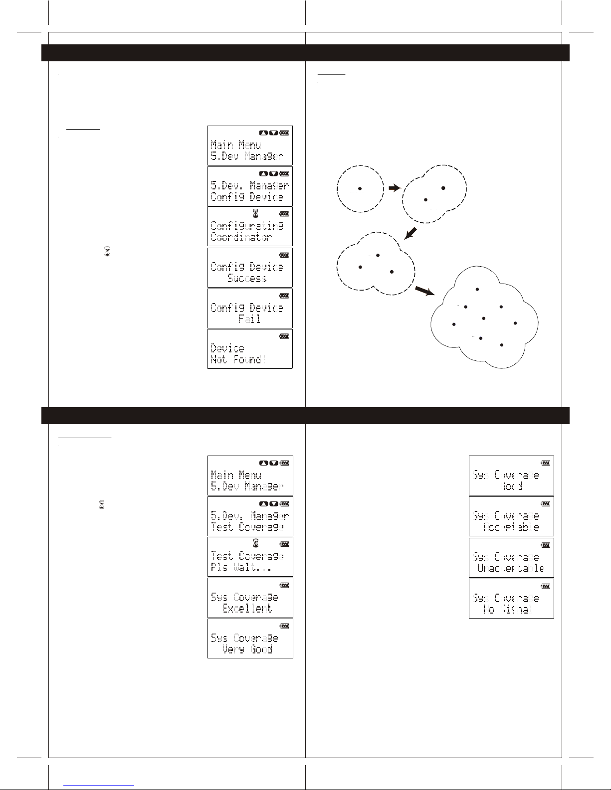
6.1 Coordinator
To configure the coordinator, perform the following
steps.
1 -Power up the Coordinator (CG100C) and Wireless
remote controller(CG100R).
2 -Connect the Wireless remote controller to the
Coordinator through the provided cable.
3 -Press the "Navigation" button of the Wireless
remote controller to enter Menu, and then scroll to
"Dev. Manager" of the Menu.
4 -Press "Yes" button to enter "Dev. Manager" Menu,
and then scroll to find "Config Device".
(Note: All the device in system need to re-configure
if the Coordinator is configured)
5 -Press "Yes" button to configure the Coordinator.
(Note: The icon is indicating that Wireless remote
controller is configuring the Coordinator)
(Note: The process to configure coordinator may
take a minute)
6 -When the coordinator is configured successfully,
the Wireless remote controller will show "Success".
During the configuration of Coordinator, if "Fail" or
"Device Not Found" is shown on the display,
please check the power of the Coordinator and the
connection between the Coordinator and Wireless
remote controller. Then perform step 1 to step 5 again.
6. Device Configuration
6.2 Device
When the Coordinator (CG100C) is configured successfully, user may configure other CG100
devices to establish network connection with the Coordinator. To achieve the best system
performance, user is strongly advised to test the system coverage of the location that is
planned to install the CG100 devices. On the other hand, when a CG100 device is configured
successfully, the system coverage will be increased by the newly added CG100 device
(Figure 6-1).
Therefore, user is strongly recommended to install and configure the CG100 devices which
are close to the Coordinator firstly for extending the system coverage for other CG100
devices which are far from the Coordinator. The procedures to test the system coverage and
to configure the CG100 devices are illustrated in Section 6.2.1 and Section 6.2.2.
Coord inator
Syst em
Cove rage
Coordi nator
System
Covera ge
New
Device
Coord inator
System
Coverage
Device
New
Device
Coordin ator
System
Coverag e
Device
New
Device
New
Device
New
Device
New
Device
New
Device
New
Device
Figure 6-1 newly added device will extend the coverage of system.
6. Device Configuration 6. Device Configuration
6.2.1 Test Converge
To test the system coverage before configurating a new device, perform following steps
1 -Place the Wireless remote controller (which is used to
configure the Coordinator before) to the location
which is planned to install the new device.
2 -Press the "Navigation" button to enter Menu, select
"Dev. Manager", and then go to "Test Coverage"
and press "Yes".
(Note: The icon is indicating the Wireless remote
controller is testing the network coverage.)
3 -After several second, the testing result will show
on the screen.
If the result is either Excellent, Very Good, Good or
Acceptable, user can install the new device to the
tested location. Otherwise, user may need to change
the installation location
After finding a correct location for device installation, user may install the new
CG100 device to such location and prepare to configure the new device.
Coordinator
System
Coverage
New
Device
Coordinator
System
Coverage
Device
Coordinator New
Device
System
Coverage New
Device
New
Device
New
Device
New
Device New
Device
New
Device
Device
Coordinator

2120
2322
6. Device Configuration
7.Group Device
6.2.2 Configuration
To configure a new CG100 device, perform following steps.
1 - Power up the new CG100 device.
2 - Connect the Wireless remote controller
(which is used to configure the Coordinator
before) to the new device through the
provided cable.
3 - Press the navigation button to enter Menu,
then select "Dev. Manager" and go to
"Config Device".
4 - Press "Yes" button to configure the new
device.
(Note: The icon is indicating the new
device is trying to connect to the network).
5 - If the device is configured successfully, the
wireless remote controller will show "Config
Device Success".
During the configuration of new device,
if "Fail" or "Device Not Found" is shown by
wireless remote controller, please check the
power of the new device and the connection
between the new device and wireless
remote controller. Then perform step 1 to
step 4 again.
Repeat steps stated in Section 6.2.1 and Section 6.2.2 to install the rest
of the devices
7.Group Device
6. Device Configuration
6.3 Wireless Remote Controller
During the configuration of coordinator, the wireless remote controller will be self-configured
automatically. User may use such wireless remote controller to configure other new device in
the network. On the other hand, when there are more than one wireless remote controller
within the system, user shall configure the other wireless remote controller (which are not used
to configure coordinator) manually before using the wireless remote controller. To configure
the handheld remote manually, perform following steps.
1 -Connect the new wireless remote controller to any
successful configured CG100 Coordinator/device
through the provided cable.
2 -Press the navigation button to enter Menu, then
select "Dev. Manager" and go to "Config Remote".
3 -Press "Yes" button to configure the wireless remote
controller.
4 -When the wireless remote controller is configured
successfully, the wireless remote controller will show
"Config Remote Success'.
During the configuration of wireless remote controller,
if "Fail" or "Device Not Found" is shown by the wireless
remote controller, please check the power of the
Coordinator/device and the connection between the
Coordinator/device and wireless remote controller. Then
perform step 1 to step 3 again
After the CG100 devices are installed and configured, user may assign a corresponding
button (1-10) on Wireless remote controller to control one or more devices (maximum three),
which is called group control. The procedures of adding device to a group and controlling
grouped devices are illustrated in Section 7.1 and Section 7.2 - 7.3 respectively.
7.1 Add Device to Group
To add device to group control, perform following steps.
1 -Connect the Wireless remote controller
(which is configured before) to the desired device
(eg. One-gang Switch, Two-gang Switch, Dimmer
Switch, Socket, etc.) through the provided cable.
2 -Press the "Navigation" button to enter Menu, then
select "Group Config".
(Note: All the groups will show on the screen, user
may scroll to view the groups.)
(Note: If there is/are device(s) added to the group,
the Wireless remote controller will show the name of the
group. eg. The default group name of the first
group is "Group 1".)
(Note: If there is no device added to the group, the
Handheld will show "(Empty)".)
3 -Press "Yes" button to select the desired group.
(Note: If there is no device added to the group, the
Handheld remote will show "No Device".)
(Note: If there is/are device(s) added to the group,
the Wireless remote controller will show the name of the
device.)
4 -Scroll down to find "Add Device"
(Note: If there are three devices already added to
the group, the "Add Device" function will be
disabled and user may not found such function
within the group.)
5 -Press "Yes" button to add device
The Wireless remote controller will show
"Press Desired Device", and the status LED of
connected device will keep flashing.
6 -Press the desired device control button on the
device to add the device to the group.
For example, when the Wireless remote controller is
connecting with the Two-gang Switch and user press
the second button of the switch, the device control
function of the second button of the switch will be
added to the group.
7 -When the device is added to the group successfully,
the Wireless remote controller will show "Add Device Success"
If "Fail" or "Device Not Found" is shown on the Wireless
remote controller during the above process, please check the
power of the Coordinator/device and the connection
between the Coordinator/device and Wireless remote controller.
And you can also check the memory information of
Wireless remote controller(see Section 9.4). Then perform
step 1 to step 6 again.
7.2 On/OFF Control
After the devices are added to different groups, user may control the group of device(s)
through a single button (1 - 10 buttons) on the Wireless remote controller.
Important: Please ensure the wireless remote controller is within the system coverage
before controlling any device.
Following examples show the procedures to control a group of device.
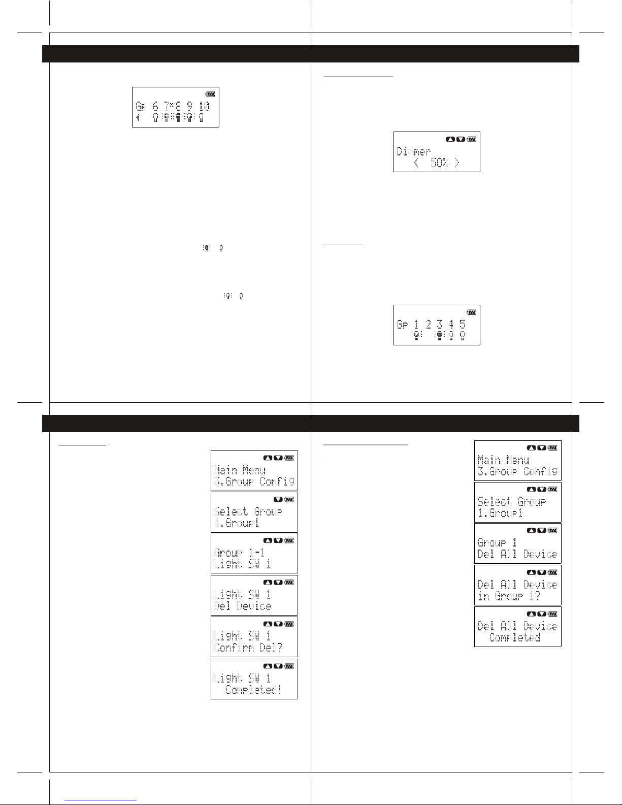
Press and hold the "Back" button to exit the menu and show the device status page.
From the above example of device status page:
Group 1: Device(s) is/are HALF ON
Group 2: No device in Group 2
Group 3: Device(s) is/are ON
Group 4: Device(s) is/are OFF
Group 5: Device(s) is/are OFF
2524
26 27
7.Group Device 7.Group Device
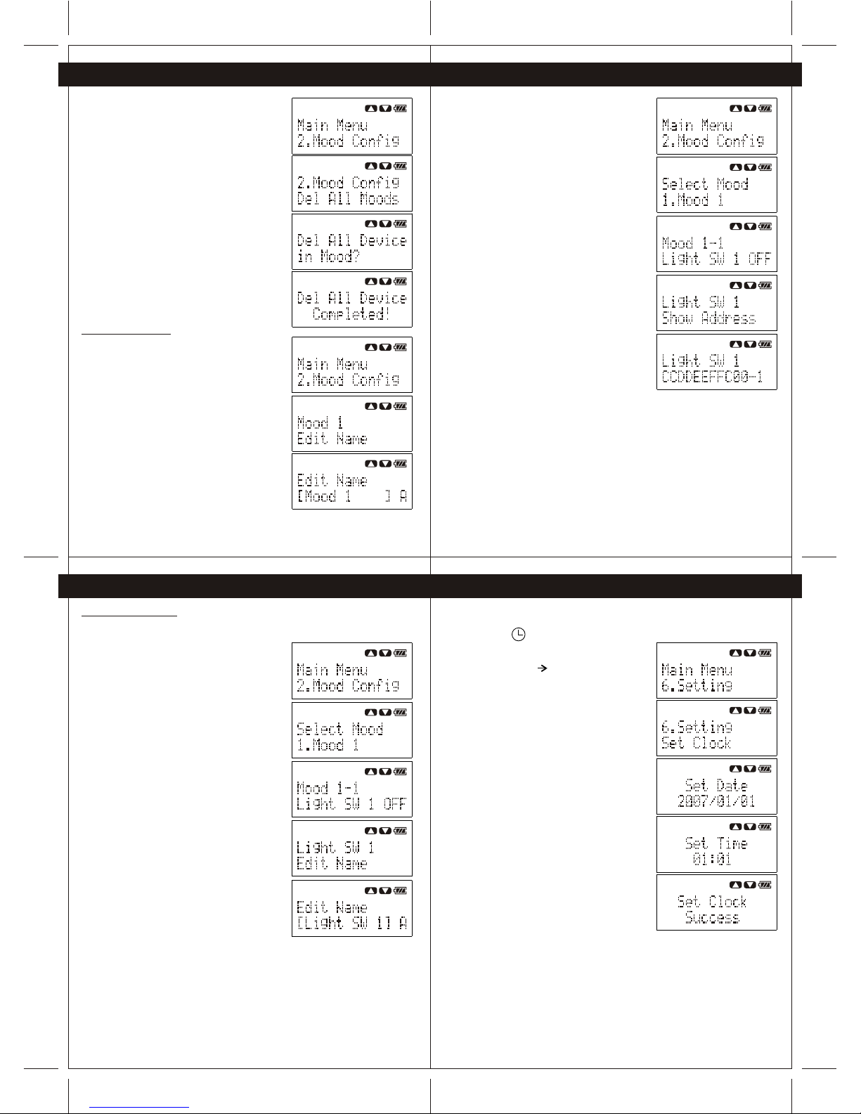
7.5 Delete Device
To delete a device in a group, perform following steps.
1- Press the "Navigation", button to enter Menu, then
select "Group Config", select the target group and
select the target device in the target group.
2- Press "Yes" button to enter the device option
menu, and then select "Del Device".
3- Press "Yes" button again to delete the device.
The Wireless remote controller will show "Confirm Del?",
user may press"Yes" button again to confirm
deleting the device or press "Back" button to
cancel.
4- If the device is deleted successfully, the Wireless
remote controller will show "Complete!".
7.Group Device 7.Group Device
User can use the "Navigation" button and push to right to show the status of group 6 to 10.
From the above example of device status page:
Group 6: Device(s) is/are OFF
Group 7: Device(s) is/are ON, and the timer function of one or
more device(s) within group 7 is/are enabled
(see Chapter 10).
Group 8: Device(s) is/are ON
Group 9: Device(s) is/are HALF ON
Group 10: Device(s) is/are OFF
User may press any button 1-10 on Wireless remote controller to turn ON/OFF of the device.
For example, the statu(s) of device(s) in group 8 is/are ON. When user presses button "8" on
Wireless remote controller, the Wireless remote controller will turn OFF all the devices in group
8.After all the devices in group 8 are OFF, the status of devices will feedback to wireless remote
controller and the status of group 8 will be changed from to
Another example, the statu (s) of device(s) in group 9 is/are HALF ON. When user presses
button "9" on Wireless remote controller, the Wireless remote controller will turn OFF all the
devices in group 9.
After all the devices in group 9 are OFF, the status of devices will feedback to Wireless
remote controller and the status of group 9 will be changed from to .
7.3 Dimmer Level Control
When all the devices within a group are dimmers (CG100DM), user may set an exact dimming
level to control the dimmers. Following example show the procedures to set dimming level of
a group of device.
Press and hold the "Back" button to exit the menu and show the device status page.
Assume all the devices in group 3 are dimmers, press the button "3" to enter dimmer level
control page.
Dimmer level control:
Left: Dim-down.
Right: Dim-up
Up: Turn ON (100%)
Down: Turn OFF (0%)
7.4 Get Status
User may update the status of devices in device status page after the remote is powered ON
or wake-up. Following example show the procedures to get the current status of devices of
in groups.
Important: Please ensure the Wireless remote controller is within the system coverage
before getting status of devices.
Press and hold the "Back" button to exit the menu and show the device status page
Press the "Back" button to update status.
7.6 Delete All Devices in Group
To delete all devices in a group, perform following steps.
1- Press the "Navigation" button to enter Menu,
then select "Group Config". Select the target group
and scroll down to find "Del All Device"
2- Press "Yes" button to delete all the devices in the
target group.
The Wireless remote controller will ask user to confirm
deleting all the device in target group, user may
press "Yes" button again to confirm deleting the
devices or press "Back" button to cancel.
3- If all the devices are deleted successfully, the
Wireless remote controller will show "Complete!"

2928
30
31
7.Group Device 8. Mood Control (Scenario)
7.Group Device 7.Group Device
7.7 Delete All Devices in All Groups
To delete all devices in all groups, perform following
steps.
1- Press the "Navigation" button to enter Menu, then
select "Group Config" and scroll down to find "Del
All Gps"
2- Press "Yes" button to delete all devices in all groups.
The Wireless remote controller will show "Del All
Device in Groups?", User may press "Yes" button again
to confirm deleting the devices or press "Back" button
to cancel.
3- If all the devices are deleted successfully, the
Wireless remote controller will show "Complete!"
7.8 Advanced Function
7.8.1 Edit Group Name
To edit the name of a group, perform following
steps.
1- Press the "Navigation" button to enter Menu, then
select "Group Config" and select the target
group, then scroll down to find "Edit Name"
2- Press "Yes" button to edit the name of selected
group.
"Left/Right" buttons: Change the position of
cursor
"ALL OFF" button" Change the case (a/A/1)
"ALL ON" button: Backspace
"Yes" button: Save the name
"Back" Button: Cancel edit name
7.8.2 Show Device Address
To view the unique address of the device, perform
following steps.
1- Press the "Navigation" button to enter Menu,
then select "Group Config", select the target
group and select the target device in the
target group
2- Press "Yes"button to enter the device option
menu, and then select "Show Address"
3- Press "Yes" button again show the unique
address of all the device.
7.8.3 Edit DeviceName
Toedit the devicename of groupeddevice, perform
following steps
1- Press the"Navigation" button toenter Menu,
then select "GroupConfig", select thetarget
group and selectthe target devicein the
target group.
2- Press "Yes" button toenter the device option
menu, and thenselect "Edit Name".
3- Press "Yes" button toedit the name of
selected device.
"Left/Right" buttons: Changethe position of
cursor
"ALL OFF" button"Change the case(a/A/1)
"ALL ON" button:Backspace
"Yes" button:Save the name
"Back" Button: Canceledit name
After the CG100 devices are installed and configured, user may add devices to different
scenario (Mood 1 to Mood 5) for mood control. The procedures of adding device to Mood and
controlling devices by Mood are illustrated in Section 8.1 and Section 8.2-8.3 respectively.
8.1 Add Device to Mood
To add a device to a mood control, perform following
steps.
1- Connect the Wireless remote controller(which is
configured before) to the desired device (eg. One-gang
Switch, Two-gang Switch, Dimmer Switch, Socket,
etc.) through the provided cable.
2- Press the "Navigation" button to enter Menu, then
select "Mood Config".
(Note: All the moods will show on the screen, user
may scroll to view the moods.)
(Note: If there is any device added to the mood, the
Wireless remote controller will show the name of the
mood. Eg. The default mood name of the first mood is
"Mood 1")
(Note: IF there is no device added to the mood, the
Handheld will show "(Empty)".)
3- Press "Yes" button to select the desired mood.
(Note: If there is no device added to the mood, the
Wireless remote controller will show "No Device".)
(Note: If there is/are device(s) added to the mood,
the Wireless remote controller will show the name and
corresponding action of the device.)
4- Scroll down to find "Add Device"
5- Press "Yes" button to add device.
The Wireless remote controller will show "Press
Desired Device", and the status LED of connected
device will keep flashing
6- Press the desired device control button on the
device to add the device to the mood.
For example, when the Wireless remote controller is
connecting with the Two-gang Switch and user
press the second of the switch, the device control
function of the second load of the switch will add to
the mood.

3332
8. Mood Control (Scenario) 8. Mood Control (Scenario)
8. Mood Control (Scenario) 8. Mood Control (Scenario)
34
35
7- When the device is added to the mood
successfully, the Wireless remote controller will show
"Add Device Success".
8- After all device is added to the mood successfully,
the Wireless remote controller will ask user to set the
action of the device during mood control.
(Note: If the device is a dimmer (CG100DM), user
may also set the dimming level of the dimmer
during mood control.)
(Note: During setting the action of the device, the
Wireless remote controller can also control the device
with the setting action for user to tune the mood.)
If "Fail" or "Device Not Found" is shown by the
Wireless remote controller during the above process,
please check the power of the Coordinator/device and
Wireless remote controller. And also please check the
memory information of Handheld remote (see Section 9.4).
Then perform step 1 to step 8 again.
8.2 Control Devices
After the devices are added to different moods, user may control the devices through the
mood control function of Wireless remote controller.
Important" Please ensure the Wireless remote controller is within the system coverage
before controlling any device.
Following examples show the procedures to apply mood control.
Press and hold the "Back" button to exit the menu and show the device status page.
Press"Yes/Mood" button to enter mood control page.
Press button "1-5" to select the desired mood.
After all the device in the selected mood are controlled, the Wireless remote controller will
show "Completed!"
If there is no device in the selected mood, the Wireless remote controller will show
"Mood is Empty".
8.3 Delete Device
Todelete a devicein a mood,perform following
steps.
1- Press the"Navigation" button toenter Menu, then
select "Mood Config".Select the targetmood
and select thetarget device inthe target mood.
2- Press "Yes" button toenter the device option
menu, and thenselect "Del Devices".
3- Press "Yes" button againto delete the device
The Wireless remotecontroller will show"Confirm
Del?",User may press"Yes" buttonagain to confirm
deleting the devicesof press "Back"button to
cancel.
4- If thedevice is deletedsuccessfully, the
Wireless remote controllerwill show "Complete!"
8.4 Delete AllDevices in AllGroups
Todelete all devicesin all mood,perform following
steps.
1- Press the"Navigation" button toenter Menu,
then select "MoodConfig", select thetarget
mood and scrolldown to find"Del AllDevice".
2- Press "Yes" button todelete all the devices in
the target mood.
The Wireless remotecontroller will askuser to
confirm.
Press "Yes"button again toconfirm deleting the
devices or press"Back" button tocancel.
3- If allthe devices aredeleted successfully,the
Wireless remote controllerwill show "Complete!'
3736
8. Mood Control (Scenario) 9. System Setting
8. Mood Control (Scenario) 8. Mood Control (Scenario)
38
39
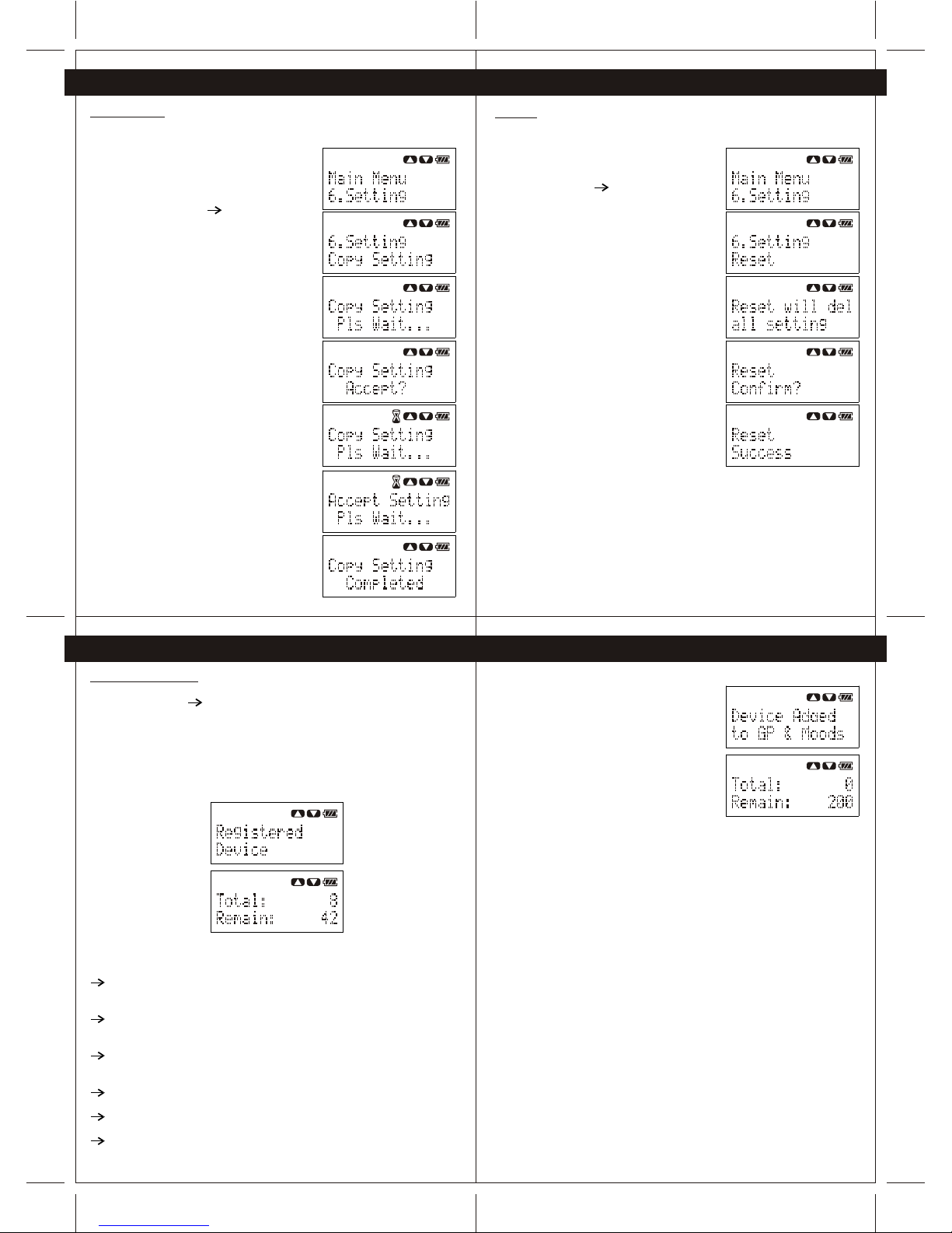
8.5 Delete AllDevices in AllGroups
Todelete all devicesin all mood,perform following
steps.
1- Press thenavigation button toenter Menu, then
select "Mood Config"and the scrolldown to find
"Del AllMoods".
2- Press "Yes" button todelete all devices in all
moods.
The wireless remotecontroller will show"Del All
Device in Moods?",User may press"Yes" button
again to confirmdeleting the devicesor press
"Back"button to cancel.
3- If allthe devices aredele4ted successfully,the
wireless remote controllerwill show "Complete!'
8.6 Advance Function
8.6.1 Edit MoodName
Toedit the nameof a group,perform following
steps.
3- Press thenavigation button toenter Menu, then
select "Mood Config"and select thetarget
mood, the scrolldown to find"Edit Name"
4- Press "Yes" button toedit the name of selected
mood.
"Left/Right" buttons: Changethe position of
cursor
"ALL OFF" button:Change the case(a/A/1)
"ALL ON" button:Backspace
"Yes" button:Save the name
"Back" Button: Canceledit name
8.6.2 Show DeviceAddress
Toview the uniqueaddress of thedevice, perform
following steps.
1- Press the"Navigation" button toenter Menu,
then select "MoodConfig". Select thetarget
mood and selectthe target devicein the target
mood.
2- Press "Yes" button toenter the device option
menu, and thenselect "ShowAddress".
3- Press "Yes" button againshow the unique address
of the device.
8.6.3 Edit DeviceName
Toedit the devicename of devicein mood, perform
following steps.
1- Press the"Navigation" button toenter Menu, then
select "Mood Config",select the targetmood
and select thetarget device inthe target mood.
2- Press "Yes" button toenter the device option
menu, and thenselect "Edit Name".
3- Press "Yes" button toedit the name of selected
device
"Left/Right" buttons: Changethe position of
cursor
"ALL OFF" button:Change the case(a/A/1)
"ALL ON" button:Backspace
"Yes" button:Save the name
"Back" Button: Canceledit name
9.1 System Clock
User is requiredto set thesystem clock fortimer control. Whenthe system clockis
not set, theicon will keepflashing on LCD.Toset the systemclock, perform
following steps:
1- Press the"Navigation" button toenter Menu, and
then select "Setting" "Set Clock".
(Note: Please ensurethe Wireless remotecontroller
is within thecoverage of the system before
setting the systemclock.)
2- Use "Navigation"button and numberbuttons
(1-10) to setthe date andthen press "Yes"
button to continue.
3- Use "Navigation"button and numberbutton
(1-10) to setthe time andthen press "Yes"
button to confirm.
After the systemclock is setsuccessfully, the
Wireless remote controllerwill show "Success".
If the systemclock is failto set, pleasecheck the
system coverage andensure the Coordinatoris
powered ON, andthen repeat step1 to 3again.
4140
9. System Setting 9. System Setting
9. System Setting 9. System Setting
42
43
9.2 Copy Setting
You areable to copythe setting ofWireless remote controllerto another Wireless
remote controller throughthe provided cable.Tocopy the setting,perform follow steps:
1- Connect thesource Wireless remotecontroller to a
destination Wireless remotecontroller through he
provided cable.
2- Press the"Navigation" button toenter Menu,
and then select"Setting" "Copy Setting" on
the source Wirelessremote controller.
3- Press anybutton on destinationWireless
remote controller towake up theremote.
4- Press "Yes" button onthe source Wireless
remote controller toprepare to copysetting.
The destination Wirelessremote controller willask
user to acceptthe setting.
5- Press "Yes" button onthe destination
Wireless remote controllerto accept thesetting.
6- Afterthe setting iscopied successfully,
both the sourceand destination Wirelessremote
controller will show"Copy Setting Completed"
9.3 Reset
User may resetthe Handheld remoteto factory defaultsetting and all the setting of
the Wireless remotecontroller will bedeleted.
Toreset the Wirelessremote controller,perform
following steps.
1- Press the"Navigation" button toenter Menu,
then select "Setting" "Reset"
2- Press "Yes" button tostart reset the Wireless
remote controller.
The Wireless remotecontroller will showthe
warning message "Resetwill del allsetting" and
then ask userto confirm.
3- If theuser confirmes todelete all the
setting, press "Yes" button againto reset the
Wireless remote controller. Otherwise, press
"Back" button tocancel the reset.
4- Afterfinishing reset process,the Wireless
remote controller willshow "Reset Success".
9.4 Memory Information
User may inquirethe memory informationof the Wirelessremote controller fromthe
setting menu ("Setting" "Memory info" ).
There are twotypes of memoryinformation showing forthe user-------- the"Registered
Device" and "DeviceAdded toGps and Moods".
9.4.1 Registered Device
The Wireless remotecontroller can registermaximum 50 devicesto the memoryfor
group or moodcontrol. The numberof device is referring to thenumber of “device loads”
added to theWireless remote controller.
There are someexamples:
When user addedthe load ofa one-gang switchto group 1of the Handheldremote
controller,
the number ofregistered device is1.
When user addedthe load ofone-gang switch togroup3, mood 1and mood 2
of the Wirelessremote controller,
the number ofregistered device isalso 1.
When user addedthe "load 1"and "load 2"of a two-gangswitch to group1 of the
Wireless remote controller,
the number ofregistered device is2.
When user addedthe "load 1"of a two-gangswitch to group1 and "load2" of thesame
two-gang switch togroup 3 ofthe Wireless remotecontroller.
the number registereddevice is 2.
When user addedthe load ofa socket togroup 1 ofthe Wireless remotecontroller
the number ofregistered device is1.
When user addedthe load ofdimmer switch togroup 1 ofthe Wireless remotecontroller
the number ofregistered device is1.
9.4.2 Device Addedto GPs andMoods
The Wireless remotecontroller can beadded with
maximum 200 devicerecords to the
memory for groupor mood control.
There are someexamples:
When user addedthe load ofa one-gang switchto group 1ofthe Wireless remote
controller,
the number ofregistered device is1.
the number ofdevice added toGps and Moodsis 1
When user addedthe load ofa one-gang switchto group 1,group 3, mood1 and
mood 2 ofthe Wireless remotecontroller,
the number ofregistered device is1.
the number ofdevice added toGps and Moodsis 4.
When user addedthe both "load1" and load2"of a two-gangswitch to group1 of the
Wireless remote controller,
the number ofregistered device is2.
the number ofof device addedto Gps andMoods is 2.
When user addedthe "load 1"of a two-gangswitch to group1 and "load2" of the
same two gangswitch to group3 of theWireless remote controller,
the number ofregistered device is2.
the number ofdevice added toGps and Moodsis 2.
When user addedthe load ofa socket togroup 1 ofthe Wireless remotecontroller,
the number ofregistered device is1.
the number ofdevice added toGps and Moodsis 1.
When user addedthe load ofa dimmer switchto group ofthe Wireless remote
controller,
the number ofregistered device is1.
the number ofof device addedto Gps andMoods is 1
When user addedthe load ofa socket toall the groups(group 1 togroup 10) andall
the moods (mood1 to mood5) of theWireless remote controller.
the number ofregistered device is1.
the number ofof device addedto Gps andMoods is 15.

4544
10. Timer Function 11. N-Way Configuration
9. System Setting 10. Timer Function
46
47
9.5 Version
Toview the firmwareversion of Wirelessremote controller,perform following steps.
1- Press the"Navigation" button toenter Menu, then
select "Setting" "About"
2- Press "Yes" button toview the firmware verison.
User is ableto configure thetimer function ofa device afterthe system clockis
configured. To configure the timer of thedevice, perform followingsteps.
Important: Please ensurethe Wireless remotecontroller is withinthe system
coverage and thetarget device isoperating before configuringthe timer function.
1- Press theNavigation button toenter Menu, and
then select "DeviceTimer"/
(Note: Allthe groups andmoods will showon
the screen, usermay scroll to view the groups
and moods.)
(Note: If thereis any deviceadded to the
group/mood, the Wirelessremote controller will
show the nameof the group/mood.)
(Note: If thereis no deviceadded to the
group/mood, the Handheldwith show
"(Empty)".)
2- Press "Yes" button toselect the desired
group/mood.
(Note: if thereis no deviceadded to thegroup,
the Wireless remotecontroller will show "No
Device".)
(Note: If thereis/are device(s) addedto the
group, the Wirelessremote controller will show
the name ofthe device.)
3- Press "Yes" button toselect the device.
The Wireless remotecontroller will getthe timer
setting of theselected device wirelessly.
4- Afterthe timer settingof the deviceis obtained
successfully, theWireless remote controllerwill
show the ONtime, OFF timeand weekly schedule
of the device.
When the timersetting is "--:--". Which is
indicating such timerfunction of thedevice is
disabled. For example,when the timersetting
of a lightswitch is
"Light SW 1ON --:--"
"Light SW 1OFF 12:02"
Which means theON timer ofthe light switchis
disabled and thelight switch willonly turn OFF
at 12:02.
5- Press "Yes" to setON and OFF timer.
If the timerfunction is disabled, press up/down
button to enablethe timer.
If user wantsto disable the timer function,
press up/down todisable the timer.
After theON/OFF timer is set, press "Yes" button
to send thenew timer setting to the device.
6- User mayalso set theweekly schedule ofthe
timer
function:
MON-SUN
MON-FRY Only
SAT&SUN Only
Monday
Tuesday
Wednesday
Thursday
Friday
Saturday
Sunday
Press "Yes"button to enableor disable the
weekly schedule
During setting theweekly schedule:
- Enabled
- Disabled
N-Way function isa special featureof the CG100devices. Through theN-Way
configuration, user mayuse a CG100device to controlthe load ofanother CG100
device wirelessly.
For example, whenthere is awall light installedin the corridorand user isdesired to
control the walllight at bothend of thecorridor. Usermay install twoone-gang
switches to bothend of thecorridor and thewall light mayconnect to only
one of theswitch (Switch B)(see Figure 11-1).
User may configurethe switchA asa N-Way Controllerand Switch Bas a N-Way
Device. AfterN-Way configuration, usercan use thecontrol button onboth
Switch Aand Switch Bto control thesame light.
Note:
When the deviceis a N-WayController, usercannot re-configure thedevice as a
N-Way Device beforeremoving the N-Wayfunction of thedevice.
When the deviceis a N-WayDevice, the usercannot re-configure thedevice as a
N-Way Controller beforeremoving the N-Wayfunction of thedevice.
Toremove the N-Wayfunction of thedevice, please referto Section 11.2..
Wireless Control
Switch A
N-Way
Controller
Switch B
N-Way
Device

4948
11. N-Way Configuration 11. N-Way Configuration
11. N-Way Configuration 11. N-Way Configuration
50
51
11.1 CheckDevice
ToCheck the deviceis configured asN-Way controller orN-Way device,
perform following steps.
1- Connect theWireless remote controllerto the
device through theprovided cable.
2- Press the"Navigation" button toenter Menu, then
select "N-Way Config" "Check Device".
3- Press "Yes" button tostart checking the device.
If the deviceis a N-Waycontroller, theWireless
remote controller willshow "Device isN-Way
Control" If thedevice is aN-Way device, the
Wireless remote controllerwill show "Deviceis
N-Way Device" Ifthe device isnot a N-Way
controller or device,the Wireless remotecontroller
will show "Deviceis Not N-Way"
11.2 RemoveN-Way Function ofDevice
Toremove the N-Wayfunction of aN-Way controller orN-Way device,
perform following steps.
1- Connect theWireless remote controllerto the
device through theprovided cable
2- Press the"Navigation" button toenter Menu,
then select "N-WayConfig" "Remove N-Way".
If the N-Wayfunction is removedsuccessfully,
the Wireless remotecontroller will show
"N-Way Config Success".
5- Afterconfigured the N-WayDevice, the N-Way
controller will tryto communicate withthe
N-Way device wirelessly. If theN-Way controller
can communicate withthe N-Way device
successfully, theWireless remote controllerwill
show "N-Way ConfigSuccess". Otherwise, the
Wireless remote controllerwill show "N-Way
Config Fail".
If N-Way functionis fail toconfigure, please
check:
- Whether thedevice is aN-Way device but
want to configureas N-Way controller.
- Whether thedevice is aN-Way controller but
want to configureas N-Way device.
- The powerof the devices.
- The cableconnection between thedevice and
Wireless remote controller.
- The wirelessconnection between twodevice.
(User may checkthe wireless connectionby using
the Wireless remotecontroller to controlthe device whichis
desired to configureas N-Way deviceat the
location of thedevice which isdesired to configure
as N-Way controller.)
11.3 Configurethe N-Way Function
Toconfigure the N-Wayfunction, perform following
steps.
1- Connect theWireless remote controllerto the
desired N-Way controllerthrough the provided
cable.
2- Press the"Navigation" button toenter Menu, then
select "N-Way Config" "Config Device".
The Wireless remotecontroller will show
"Press Desired Controller",and the statusLED of
connected device willkeep flashing.
User may pressthe desired devicecontrol
button on thedevice to configure the control
button with N-WayController function.
When the desiredcontrol button ispressed,
the Wireless remotecontroller will show
"Controller set Finished"
3- Afterconfigured the desiredcontroller, the
Wireless remote controllerwill show "Plsconnect
other Device" and"Then Press "OK"Or
"Yes"".Connect theWireless remote controllerto
the desired N-Waydevice through theprovided
cable and thepress "Yes"buttonto configure
the N-Way device.
4- The Wirelessremote controller willshow "Press
Desired Device", andthe status LEDof connected
device will keepflashing.
User may pressthe desired devicecontrol
button on thedevice to configurethe load of
device to bea N-Way device.
When the desiredcontrol button ispressed,
the Wireless remotecontroller will show"Device Set
Finished".
53
12. APPENDIX 12. APPENDIX
54
55
12.3 TroubleShootingGuide
Symptom Possible Cause Solution
7. Unknown Try switch offthe MCB, 30
seconds later, switchOn again
1.Wires are not properly
secured or connected in
the terminals
2.MCB is OFF or has been
tripped
3.Fuse has blown out
4.Lightbulbs are not properly
installed or lightbulbs have
burned out
5.The Service switch is in off
position
6.Unknown
7.Improper loads are
connected
Make sure the wires are secured,
screws are fastened and the Live,
Neutral or load wires have been
connected to the correct terminals
Switch on the MCB . If a breaker
continually trips, contact a
registered electrician to determine
the cause of the problem.
Replace the fuse with one of the
same rating
Reinstall the lightbulbs or replace
the light bulbs
Remove the cover plate, and slide
the service switch to ON position
Remove the cover plate, push the
Reset button once
Refer to section 12.1, and check
the load type
Main Light or LEDindicator
does not turn ON
1.Not programmed properly
2.Battery of remote control
is too low
4.Wiring is not correct
5.Physical distance
between two devices is
too far.
6.Remote control is toofar
away
Refer to "Installation of
System" section of thismanual
Replace new battery forRemote
Make sure supply voltageis
within the specification
Re-check wiring according to
this manual
Relocate the devices oradd
another device between them
Try closer location, or add one
more device at boundary
location to extend thecontrol
distance
3.AC Voltage istoo low
Devices is not responding to
the Wireless Remote Controller
1.Provided cable is not
plugged firmly
2.Battery level of Handheld
Remote is too low
3.Improper programming
method
4.Wiring is not correct
5.Fuse is broken ornot
installed
6.Over maximum number
of devices
7.Service switch is inOff
position
Check cable, unplug andthen
plug in again
Replace with new battery
Refer to "Installation of
System" section of thismanual
Check fuse
Check wiring according tothis
manual
Maximum number of devicesis
50, Maximum records is200
Check switch position
Unable to program
52
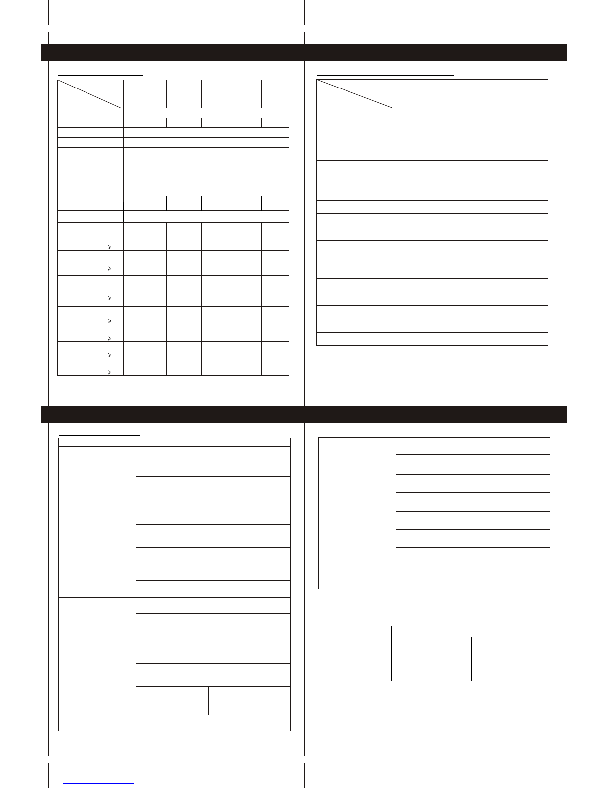
12.1 Specifications--Devices
Specification
Product
Line Frequency
COORDINATOR
(1 Gang switch)
1 Gang Switch 2 Gang Switch AC socket
CG201DM
CG201C CG201S1 CG201S2 CG201SK
Dimmer
Voltage 220 to 240Vac
Maximum Load
Communication standard
Bi-directional control
Radio Frequency
Operating Temperature
Operating Humidity
Mounting Centers
10Amp/250V
Ceramic Tube Fuse
(Time Lag)
Fuse Typeand Rated
Current
2000W 1000W x 2 13A 400W
50 Hz
IEEE802.15.4 ( ZigbeeTechnology)
Yes
2.4GHz
0 to 40 degC
0% to 95%
60.3mm
2000W
Load type
Incandescent Lamp
Fluorescent Lamp
Low voltage
Halogen lamp(12V)
(with Transformer)
Low voltage
Halogen lamp(12V)
(with Dimmable
Electronic
Transformer)
Campact
Fluorescent lamp
Cold Cathode
Neon lamp
Halogen lamp
( 220V)
Energy Saving
Lamp
Yes
Yes
Yes
Yes
Yes
Yes
Yes
Yes
Yes
Yes
Yes
Yes
Yes
Yes
Yes
Yes
Yes
Yes
Yes
Yes
Yes
Yes
Yes
Yes
Yes
Yes
Yes
Yes
Yes
Yes
Yes
Yes
Yes
Not
applicable
Not
applicable
Yes
Yes
Not
applicable
Not
applicable
Not
applicable
12.2 Specifications WirelessRemote Controller
On/off Switch, Dimmer, All on,All off,Device excluding
capability in Allon/ All, Scenariosetting, Timer,RealtimeTime
clock, Device setting, Networking,
Bi-directional control, Device statusmonitoring, Device
Grouping, Multi-way switch setting,Device name Editing,
Remote name Editing. Navigationcontrol setting
Specification
Product Wirless Remote Controller
Control Function
Scenario setting
LCD display
LCD backlight
Battery level indicator
Device control
Battery
Transmission distance
5 Mood Settings
Dot matrix LCD distpaly, STN type
White colour
4 levels
Up to 50
2 x AAA Alkaline Batteries
Over 60M in openarea, (Transmission distancecan be
extended if more devicesare installed - -Wireless Networking
Technology)
Communication Standard
Bi-directional control
Radio Frequency
Operating Temperature
Operating Humidity
IEEE802.15.4 ( ZigbeeTechnology)
Yes
2.4GHz
0 to 40 degC
0% to 95%
12. APPENDIX 12. APPENDIX
Ranges of rated currents
up to and including 4
above 4 up to and including 6
above 6 up to and including 10
Check the Memory infoof
Wireless Remote controller
according to section 9.4
Timer function Yes
Power
Factor
0.85
---
Power
Factor
0.85
Power
Factor
0.85
Power
Factor
0.85
Power
Factor
0.85
Power
Factor
0.85
Power
Factor
0.85
Detail
10Amp/250V
Ceramic Tube Fuse
(Time Lag)
10Amp/250V
Ceramic Tube Fuse
(Time Lag)
BS1362
13A Fuse
5Amp/250V
Ceramic Tube Fuse
(Time Lag)
Rigid conductors (solid orstranded)
Nominal cross-sectional areas
mm
Diameter of largest conductor
mm
A
-
From 0.75 up to 1.5 inclusive
From 1 up to 2.5 inclusive
-
1.45
2.13
2
2
1)
2
3)
12.4
This manual suits for next models
6
Table of contents
Popular Home Automation manuals by other brands


Leviton
Leviton Decora Smart DZPA1 installation instructions

Aqila
Aqila Securehub user guide

X10
X10 HK10A SUPERREMOTE owner's manual

Silux Control
Silux Control Tylten Pro Operation manual

SOMFY
SOMFY DIY AUTOMATION KIT installation guide

RADEMACHER
RADEMACHER RolloTron Basis 1100 Translation of the Original Operating and Assembly Manual