CLA-VAL e-Lift-34 User manual

CLA-VAL e-Lift-34
Electronic Valve Position Indicator
CLA-VAL Europe www.cla-val.ch [email protected] 1-LIN071UE - 08/15
© Copyright CLA-VAL Europe - Specifications subject to change without notice - no contractual illustrations.
User Manual

CLA-VAL e-Lift-34
Electronic Valve Position Indicator
CLA-VAL Europe www.cla-val.ch [email protected] 2-LIN071UE - 08/15
© Copyright CLA-VAL Europe - Specifications subject to change without notice - no contractual illustrations.
Table of Contents
1
Introduction........................................................................................................................3
1.1Precautions Before Starting ......................................................................................................3
1.2Troubleshooting ........................................................................................................................3
1.3General Disclaimer ...................................................................................................................3
1.4Environmental Protection..........................................................................................................3
1.5Typography...............................................................................................................................3
2
e-Lift Characteristics.........................................................................................................4
3
How to Use the e-Lift?.......................................................................................................5
3.1Wiring Diagram .........................................................................................................................5
3.2Technical Data..........................................................................................................................6
3.3Connection................................................................................................................................6
3.4Installation Instructions .............................................................................................................7
3.4.1Assembly Details ...............................................................................................................................7
4
Calibration..........................................................................................................................8
4.1Calibration with Water & without Calibration Tool.....................................................................8
4.2Calibration with the Calibration Tool & without Water...............................................................9
5
Option Menu.....................................................................................................................11
5.1Factory Reset..........................................................................................................................11
5.2Inverting the 4-20 mA Signal...................................................................................................12

CLA-VAL e-Lift-34
Electronic Valve Position Indicator
CLA-VAL Europe www.cla-val.ch [email protected] 3-LIN071UE - 08/15
© Copyright CLA-VAL Europe - Specifications subject to change without notice - no contractual illustrations.
1 INTRODUCTION
1.1 PRECAUTIONS BEFORE STARTING
: Installation and electrical connection should be carried out in accordance with local regulations and only by qualified
technicians!
1.2 TROUBLESHOOTING
Diagnostic for the LED
- At start-up, the LED remains red for 1 second, and then switches to solid Green.
Blinking Green
- Calibration mode.
Permanente Red
- Error, the magnet is not within the proximity of the sensor or is out of the range.
Green
- Status OK.
Instability of the signal 4-20 mA
- Check if the pipe is connected to the ground; connect the 0 V of the 24 V to the same ground.
- Make sure the e-Lift is not located in an area near high voltage or a variable-frequency drive.
1.3 GENERAL DISCLAIMER
In accordance with our policy of continuous development and improvement, CLA-VAL Europe reserves the right to modify or
improve these products at any time without prior notice. CLA-VAL Europe assumes no liability or responsibility for any errors
or omissions in the content of this document.
1.4 ENVIRONMENTAL PROTECTION
Help to preserve and protect the environment. Recycle used batteries and accessories.
1.5 TYPOGRAPHY
Throughout this manual, the following typographical conventions and symbols have been adopted to help readability:
a. "Bold": Menu, command, tab and button.
b. BOLD ITALIC: Important information.
c. (1): Number of the reference marks on image.
d. www.cla-val.ch: Internet address.
e. : Some tips.
f. : Warning!
CLA-VAL e-Lift-34
Electronic Valve Position Indicator
CLA-VAL Europe www.cla-val.ch [email protected] 4-LIN071UE - 08/15
© Copyright CLA-VAL Europe - Specifications subject to change without notice - no contractual illustrations.
2 E-LIFT CHARACTERISTICS
Thank you for purchasing a CLA-VAL e-Lift. With appropriate care, this e-Lift will provide accurate and reliable control of
your valve for many years. The e-Lift is built with the latest technology together with very high quality components.
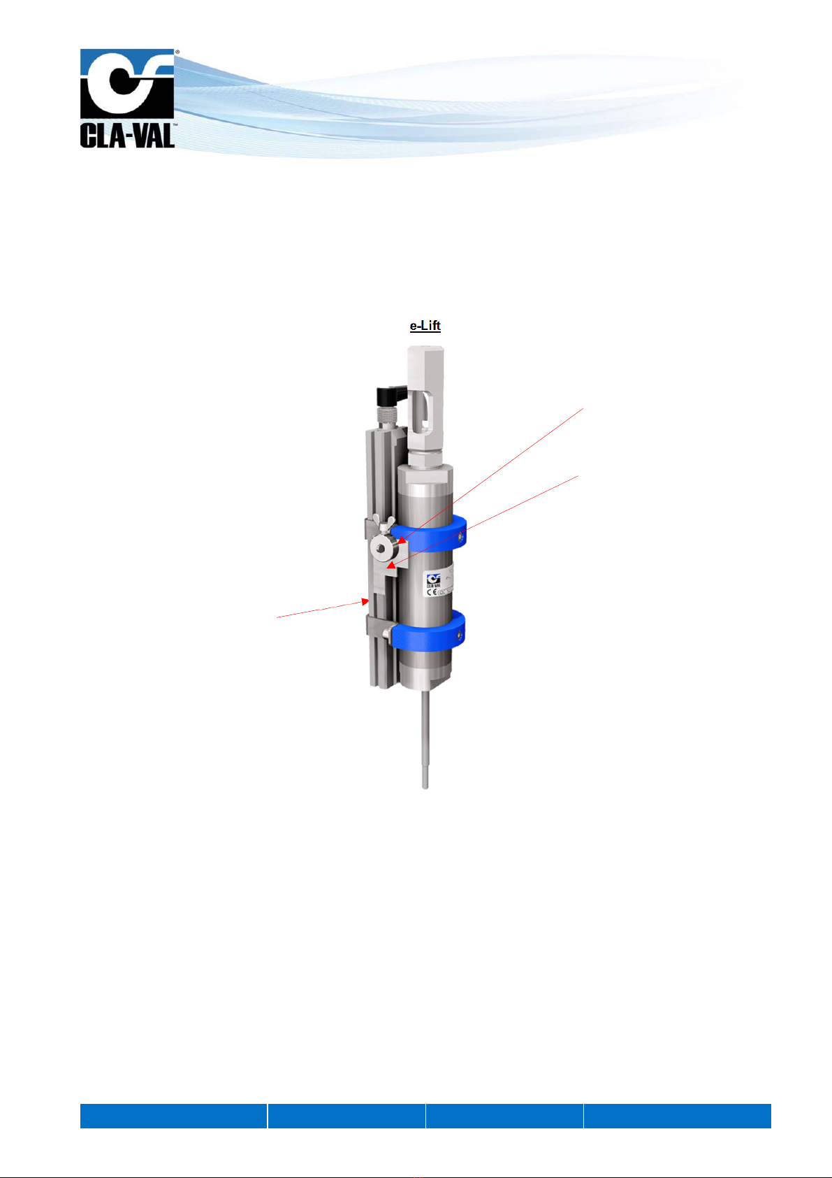
The e-Lift is a unique electronic contact-less valve position indicator. The push buttons included in the junction box provide
an easy method for calibrating your valves.
e-Lift
Electronic sensor
device
Tools for calibration
Wedge
CLA-VAL e-Lift-34
Electronic Valve Position Indicator
CLA-VAL Europe www.cla-val.ch [email protected] 5-LIN071UE - 08/15
© Copyright CLA-VAL Europe - Specifications subject to change without notice - no contractual illustrations.
3 HOW TO USE THE E-LIFT?
3.1 WIRING DIAGRAM
: To improve the EMC, it is strongly recommended to link the 0 V to the earth.
Cable
Cable Entrées Inputs
Code Fonction Function
0 V Masse = à connecter avec la
terre principale bleu Ground = to connect with main
ground blue
DC Alimentation de 10 à 30 VDC brun Power supply 10 to 30 VDC brown
4-20 mA Sortie 4-20 mA (+) vert 4-20 mA output (+) green
4-20 mA Sortie 4-20 mA (-) gris 4-20 mA output (-) grey
LA Entrée programmation N°1 rouge Programming input N°1 red
LB Entrée programmation N°2 blanc Programming input N°2 white
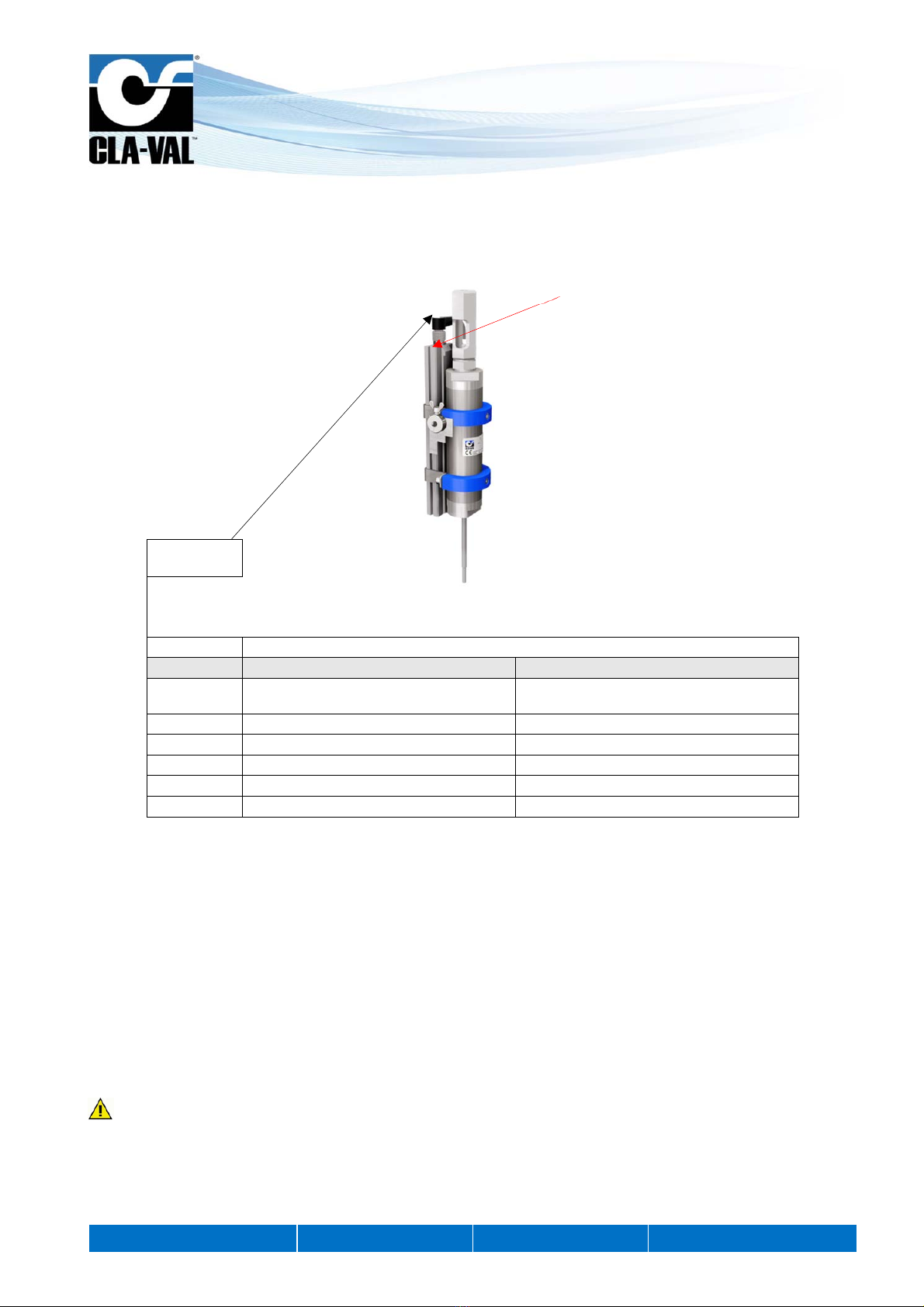
LED indicator

CLA-VAL e-Lift-34
Electronic Valve Position Indicator
CLA-VAL Europe www.cla-val.ch [email protected] 6-LIN071UE - 08/15
© Copyright CLA-VAL Europe - Specifications subject to change without notice - no contractual illustrations.
3.2 TECHNICAL DATA
Electrical Specifications
Electrical Power: 10 to 30 VDC +/- 1%, 100 mA load draw, max peak 900 mA
Power protection: Max. 32 VDC over voltage, reverse polarity & short circuit
70°C stop @ high temperature
Led display: Green & Red LED
Electrical connection: 1x 5 or 10 meters shielded cable (8 wires)
Wire section 0.25 mm2
Cable section 7 mm
Output position & accuracy: 1x 4-20 mA (Output charge ≤500 Ω)
Output 4-20 mA protection: Max. 32 VDC over voltage (Output analogue has the same Common, not
isolated)
Other Specifications
Temperature range: -10°C to +70°C (Electronic only)
Protection: IP68, [validated 1 month at 0.2 bar (2 m water depth)]
Interface: 2x push buttons in a junction box
Optionally CLA-VAL D22 Electronic Valve Controller
Default mode
Troubleshooting: Refer to user manual for LED diagnostics and codes: (Red-Green blinking)
: The e-Lift uses a magnetic sensor; take care to keep the installation free of any magnetic fields (transformers, motors,
high power supply, etc…).
3.3 CONNECTION
Output

CLA-VAL e-Lift-34
Electronic Valve Position Indicator
CLA-VAL Europe www.cla-val.ch [email protected] 7-LIN071UE - 08/15
© Copyright CLA-VAL Europe - Specifications subject to change without notice - no contractual illustrations.
3.4 INSTALLATION INSTRUCTIONS
1. All installation, adjustment and maintenance should be carried out by a competent electrician.
2. Do not exceed the maximum ratings given in the specifications and printed on the label.
3. The electrical connections should be made as described in the user’s manual.
4. Before any maintenance operation the main power should be turned off.
5. Don’t forget to put the spring into the tube after fitting the magnet holder.
6. Make sure the e-Lift rod is located at the bottom of the valve stem.
: Do not attempt to open the product as this will invalidate the warranty!
3.4.1 ASSEMBLY DETAILS
Mounting direction of the sensor
Sticker front of tube face
Junction box with terminal and
push button of calibration
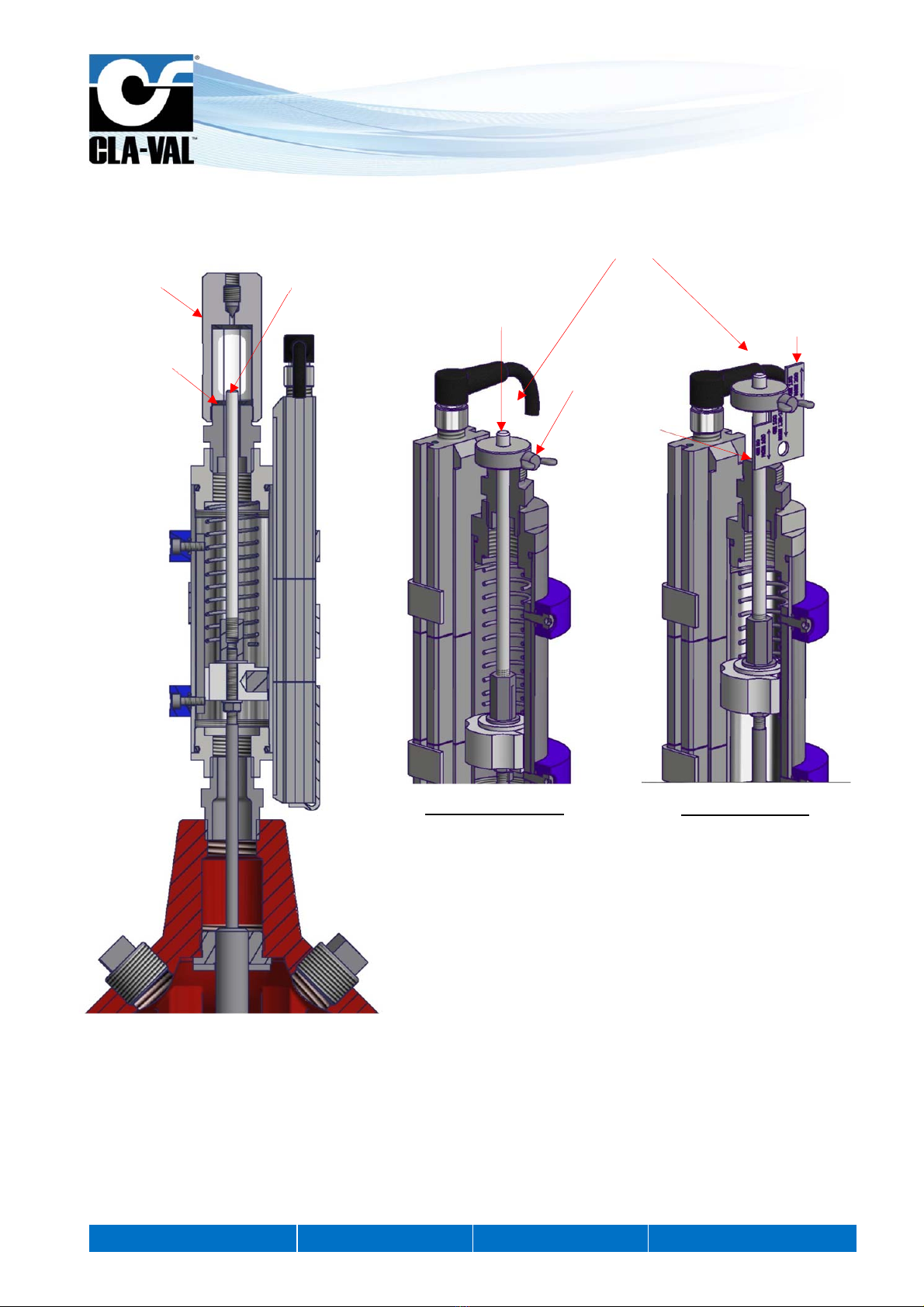
Cut view
Spring
Magnet
Rod
Stem
Magnetic sensor
Anti-rotation plate
Magnet holder
CLA-VAL e-Lift-34
Electronic Valve Position Indicator
CLA-VAL Europe www.cla-val.ch [email protected] 8-LIN071UE - 08/15
© Copyright CLA-VAL Europe - Specifications subject to change without notice - no contractual illustrations.
4 CALIBRATION
4.1 CALIBRATION WITH WATER & WITHOUT CALIBRATION TOOL
Initial situation: The magnet of e-Lift should be within measuring range sensor; The LED should be green before starting
calibration.
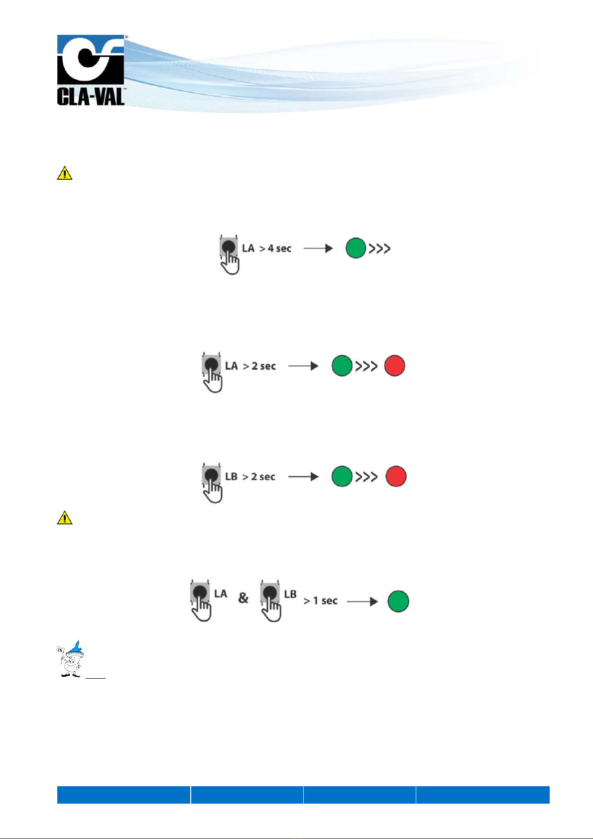
1. Activate calibration mode
- Press button marked LA for at least 4 secs. or until the LED starts blinking green.
2. Set 0% closed position
- Close the valve to reach lowest position.
- Press button marked LA for at least 2 secs. or until the LED appears red.
3. Set 100% open position
- Open the valve to reach the highest position.
- Press button marked LB for at least 2 secs. or until a solid red LED appears.
If the time taken to fully open the valve from the closed position exceeds 40 seconds, the calibration process times out
and you will need to repeat the process. Please proceed step 1 first then step 3.
4. End calibration mode
- Press buttons LA and LB simultaneously (< 1s) to finish calibration and read current value.
Note:
Any of the individual steps for settings can be selected independently. The calibration process can be ended at any time
(step 4).
This mode shows how the valve was calibrated without tools.
CLA-VAL e-Lift-34
Electronic Valve Position Indicator
CLA-VAL Europe www.cla-val.ch [email protected] 9-LIN071UE - 08/15
© Copyright CLA-VAL Europe - Specifications subject to change without notice - no contractual illustrations.
4.2 CALIBRATION WITH THE CALIBRATION TOOL & WITHOUT WATER
Mechanical details:
X101 Delrin stem
e-Lift surface
Wing screw
Closed position view
Delrin stem Wedge
e-Lift surface
Open position view
Adapt
Wedge
position
according to
size of valve
Calibration tool

CLA-VAL e-Lift-34
Electronic Valve Position Indicator
CLA-VAL Europe www.cla-val.ch [email protected] 10 -LIN071UE - 08/15
© Copyright CLA-VAL Europe - Specifications subject to change without notice - no contractual illustrations.
The e-Lift can be calibrated using the calibration tool and push buttons in the junction box (or optionally with the D22
Electronic Valve Controller interface). Alternatively, please isolate the main valve cover chamber before proceeding with
calibration using the tools.
1. Close the main valve
2. Unscrew the X101 stem position indicator (if supplied)
3. In place of the X101, insert the calibration tool with the wing screw unscrewed on the Delrin (white plastic) stem
4. Once the calibration tool is placed on the Delrin stem & e-Lift surface position, screw the wing screw onto the Derlin
stem
5. Activate calibration mode
- Press the LA button for at least 4 secs. until the LED starts blinking green.
6. Set 0% Close Position
- Press the LA button for at least 2 secs. until the LED appears solid red.
7. After setting the new closed position, lift the calibration tool and place the wedge corresponding to the valve size
between the surface of the e-Lift and the nut of the calibration tool (see drawing above).
8. Set 100% Open position
- Press the LB button for at least 2 secs. until the LED appears solid red.
9. End calibration mode
- Press buttons: LA and LB simultaneously (< 1sec.) to finish calibration and read current values.
10. Remove wedge then unscrew the calibration tool from the Delrin stem
11. Once the calibration tool is removed, replace the X101 (if supplied)
12. Open the isolation cocks to restore valve operate
The calibration is completed!
CLA-VAL e-Lift-34
Electronic Valve Position Indicator
CLA-VAL Europe www.cla-val.ch [email protected] 11 -LIN071UE - 08/15
© Copyright CLA-VAL Europe - Specifications subject to change without notice - no contractual illustrations.
5 OPTION MENU
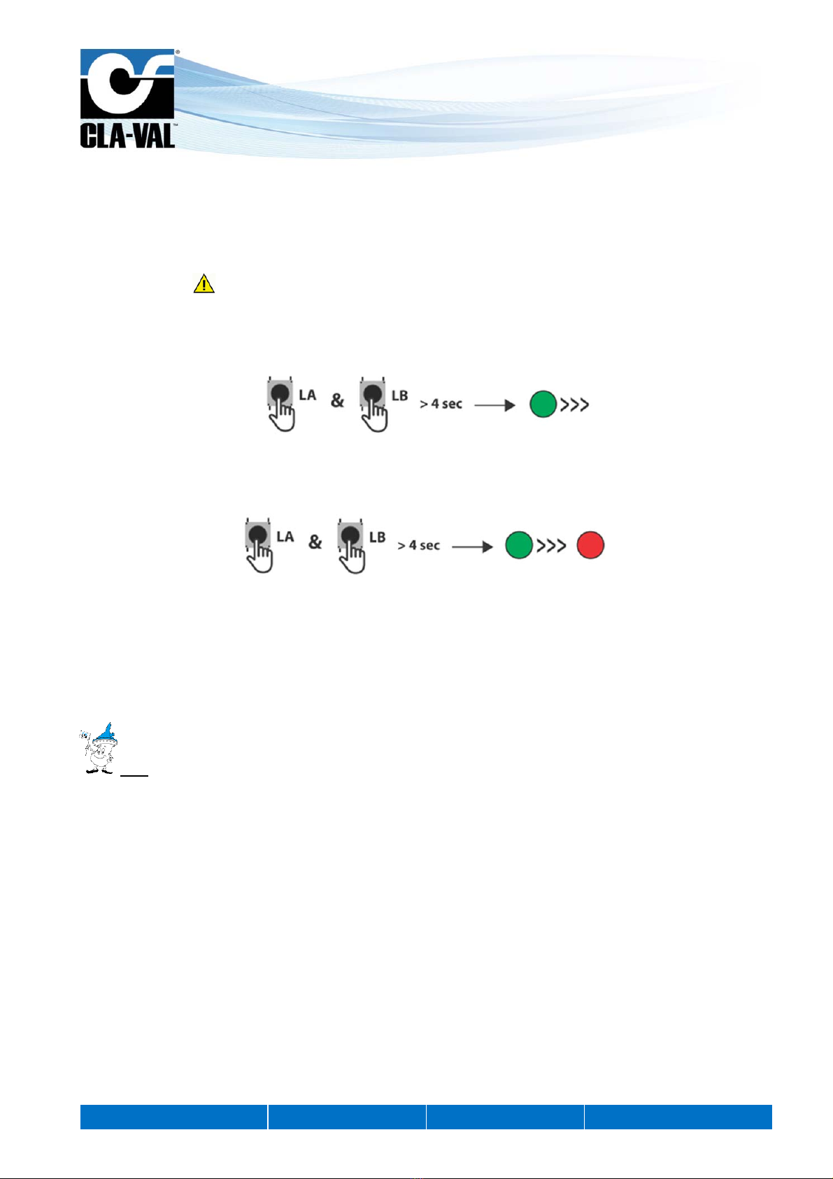
5.1 FACTORY RESET
The e-Lift can be reset to restore all setting to the factory settings.
Please note if using factory reset, all values and positions displayed will be lost.
1. Activate reset
- Press buttons LA and LB simultaneously for at least 4 secs. until the LED starts blinking green.
2. Reset
- Pressure buttons LA and LB simultaneously for at least 4 secs. until the LED appears red to complete the reset.
3. After reset
- All values are reset.
- Current position of the magnet is displayed.
- Reset is deactivated (permanent green LED).
Note:
Resetting can be aborted without any changes before step 2.
To abort reset, activate LA & LB simultaneously (< 1sec).
CLA-VAL e-Lift-34
Electronic Valve Position Indicator
CLA-VAL Europe www.cla-val.ch [email protected] 12 -LIN071UE - 08/15
© Copyright CLA-VAL Europe - Specifications subject to change without notice - no contractual illustrations.
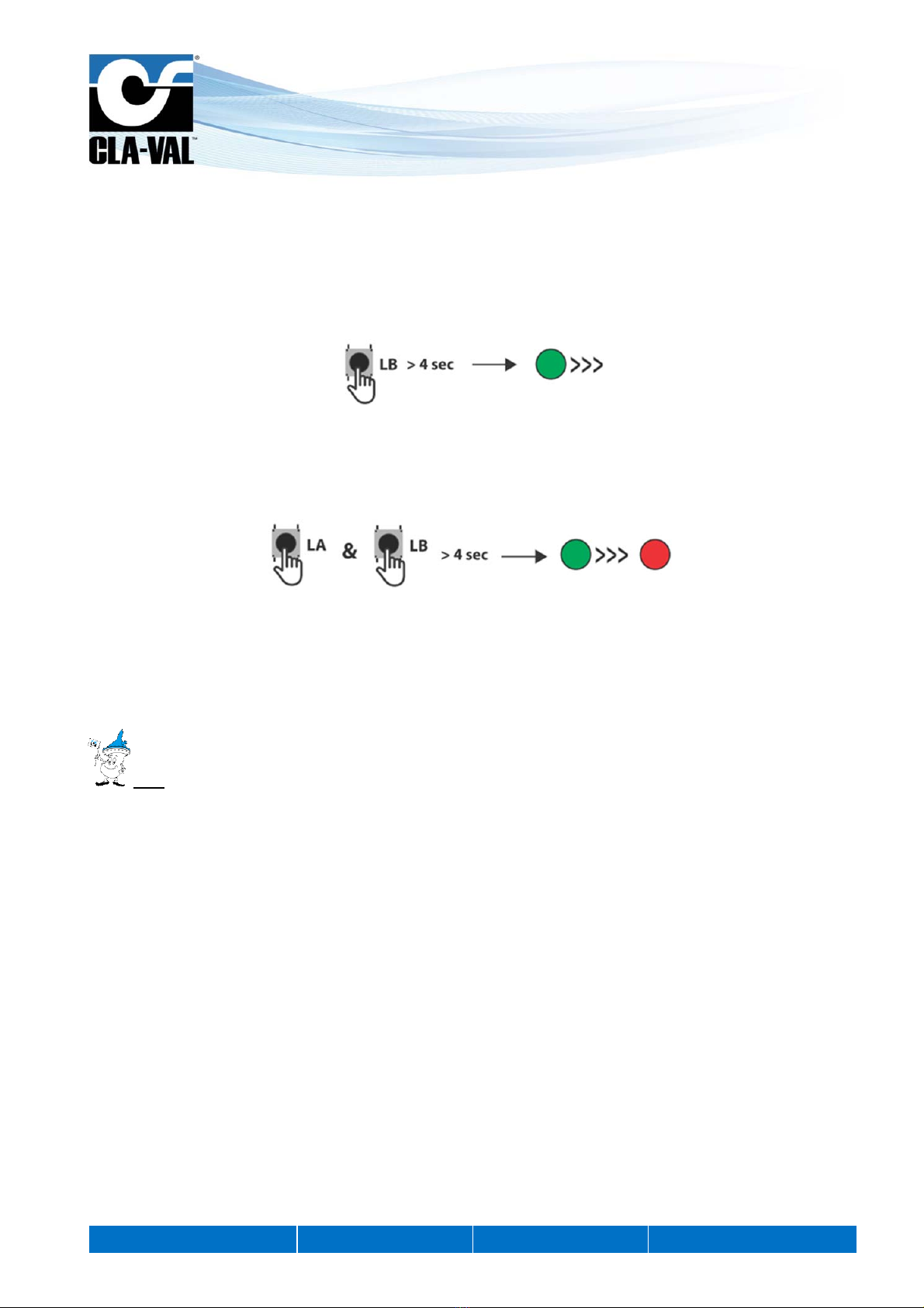
5.2 INVERTING THE 4-20 MA SIGNAL
The signal 4-20 mA of the e-Lift can be inversed (valve close = 20 mA & valve fully open = 4 mA).
This option can be useful in some cases for SCADA systems.
1. Activate invert
- Press button LB button at least 4 secs. until the LED starts blinking green.
2. Invert signal
- Press buttons LA and LB simultaneously for at least 4 secs until the solid red LED appears to complete the invert
signal.
3. After inverting
- The output signal is inverted.
- Current position of magnet is displayed.
- Inverting is deactivated (permanent green LED).
Note:
Inverting can be aborted without any changes before step 2.
To abort inverting, activate LA & LB simultaneously (< 1 s).
Table of contents
Other CLA-VAL Measuring Instrument manuals


Popular Measuring Instrument manuals by other brands

Endress+Hauser
Endress+Hauser Proline Promag 50 operating instructions

Laser Reference
Laser Reference ProShot L5 Operation guide

Hanna Instruments
Hanna Instruments HI 96759C instruction manual

PFlow Industries
PFlow Industries P116 instruction manual

Endress+Hauser
Endress+Hauser Gammapilot FMG50 technical information

Gutermann
Gutermann HISCAN Safety Guidelines & Installation Manual


