CLA-VAL X144D e-FlowMeter Owner's manual


A view inside the X144D e-FlowMeter
Plug-and-Play Metering:Cla-Val X144D e-FlowMeter
Proven Technology from
the Industry Leader
Laboratory Tested • Field Proven • Performance Assured
Log-on to
www.cla-val.com and click Electronic
Products to learn more about our
complete line of e-products.
flow direction

X144D e-FlowMeter Installation,
Operation and Maintenance
Table o Contents
Topic Page #
ntroduction . . . . . . . . . . . . . . . . . . . . . . . . . . . . . . . . . . . . . . . . . . . . . . . . . . . . . . . . . . . . . . . 4
Section1:System Components and How They Work:
1.1 - Theory of Operation . . . . . . . . . . . . . . . . . . . . . . . . . . . . . . . . . . . . . . . . . . . . . . . . . . 5
1.2 - Supplied Parts List . . . . . . . . . . . . . . . . . . . . . . . . . . . . . . . . . . . . . . . . . . . . . . . . . . . 6
1.3 - Non-Supplied Parts List. . . . . . . . . . . . . . . . . . . . . . . . . . . . . . . . . . . . . . . . . . . . . . . . 7
Section 2: nstallation & Removal of the X144D e-FlowMeter
2.1 - Installation Location Recommendations . . . . . . . . . . . . . . . . . . . . . . . . . . . . . . . . . . . 8
2.2 - Materials Required for Installation. . . . . . . . . . . . . . . . . . . . . . . . . . . . . . . . . . . . . . . . 9
2.3 - Mounting the X144D e- lowMeter . . . . . . . . . . . . . . . . . . . . . . . . . . . . . . . . . . . . . . . 10
2.4 - Step-By-Step Instructions: Mechanical Installation . . . . . . . . . . . . . . . . . . . . . . . . . 11-14
2.5 - Step-By-Step Instructions: Wiring Diagrams . . . . . . . . . . . . . . . . . . . . . . . . . . . . . . 15-17
2.6 - VC-22D Wiring Schematic . . . . . . . . . . . . . . . . . . . . . . . . . . . . . . . . . . . . . . . . . . . . . 18
Section 3: X144D e-FlowMeter Configuration and Startup
3.1 - Startup Checklist . . . . . . . . . . . . . . . . . . . . . . . . . . . . . . . . . . . . . . . . . . . . . . . . . . . . 19
3.2 - Shutdown / Removal of the X144D e- lowMeter. . . . . . . . . . . . . . . . . . . . . . . . . . . 20-21
3.3 - Programming . . . . . . . . . . . . . . . . . . . . . . . . . . . . . . . . . . . . . . . . . . . . . . . . . . . . . . 22-24
Section 4: Maintenance and Repair
4.1 - Routine Maintenance . . . . . . . . . . . . . . . . . . . . . . . . . . . . . . . . . . . . . . . . . . . . . . . . . 25
4.2 - Cleaning Debris from Measurement Cylinder . . . . . . . . . . . . . . . . . . . . . . . . . . . . . . 25
4.3 - Dealing with Sensor Tip Damage. . . . . . . . . . . . . . . . . . . . . . . . . . . . . . . . . . . . . . . . 25
Section 5:Specifications
Table 2: Electrical Specifications . . . . . . . . . . . . . . . . . . . . . . . . . . . . . . . . . . . . . . . . . . . . 26
Table 3: Mechanical Specifications. . . . . . . . . . . . . . . . . . . . . . . . . . . . . . . . . . . . . . . . . . . 26
Dimensional Drawing: X144D e- lowMeter . . . . . . . . . . . . . . . . . . . . . . . . . . . . . . . . . . . . 27
Table 4: X144D e- lowMeter Dimensions . . . . . . . . . . . . . . . . . . . . . . . . . . . . . . . . . . . . . 27
Dimensional Drawing/Data: Insertion Tool . . . . . . . . . . . . . . . . . . . . . . . . . . . . . . . . . . . . . 28
Table 5: Insertion Tool Chart. . . . . . . . . . . . . . . . . . . . . . . . . . . . . . . . . . . . . . . . . . . . . . . . 28
Table 6: low Ranges . . . . . . . . . . . . . . . . . . . . . . . . . . . . . . . . . . . . . . . . . . . . . . . . . . . . . 29
Table 7: X144D e- lowMeter Analog Range (4-20mA Scaling):. . . . . . . . . . . . . . . . . . . . . 29
actory Settings
Appendix
Quick Start Installation and Removal Instructions . . . . . . . . . . . . . . . . . . . . . . . . . . . . . . 30-33
Quick Start Programming. . . . . . . . . . . . . . . . . . . . . . . . . . . . . . . . . . . . . . . . . . . . . . . . . 34-37
Menu Structure Overview . . . . . . . . . . . . . . . . . . . . . . . . . . . . . . . . . . . . . . . . . . . . . . . . . . 38
Troubleshooting Guide. . . . . . . . . . . . . . . . . . . . . . . . . . . . . . . . . . . . . . . . . . . . . . . . . . . 39-41
X144 to X144D Retrofit Kit Instructions . . . . . . . . . . . . . . . . . . . . . . . . . . . . . . . . . . . . . . 42-46
www.cla-val.com

4
NTRODUCT ON:
X144D e-FlowMeter nstallation, Maintenance and Operation
The X144D is an insertion flow meter designed to provide flow information from inside a Cla-Val Control
valve.This innovative device measures flow information using standard Cla-Val control valve bodies at locations
where typical flow meters cannot provide accurate measurements. As opposed to industry standard insertion
flow meters, the X144D e- lowMeter can be installed directly into the inlet side of a Cla-Val Control Valve,
eliminating the need for costly downtime and pipe work. The X144D can also be inserted in valves at piping
locations not usually permitted for flow measurement, such as directly downstream of a flow disturbance such
as elbows, valves or reducer within just a few pipe diameters (see installation recommendations for conditions.)
This manual will help you install, operate, and maintain the X144D e- lowMeter.
mportant Safety nformation
The following safety notices are used in this manual:
• CAUT ON: indicates that minor personal injury, product or property damage may occur if
the notice is ignored.
• NOTE: indicates special instructions that are important but are not related to hazards.
Please see examples shown below:
NOTE:The X144D e- lowMeter may
be installed in inlet tap of either side of
the Cla-Val Automatic Control Valve.
CAUT ON: ailure to install the unit
correctly could result in faulty operation
and/or damage to the unit.
CAUT ON:
Valve in which X144D e- lowMeters
are installed MUST have upstream
and downstream Isolation Valves to
ensure that the line is locked out and
not under pressure during
installation, maintenance or removal
of the X144D e- lowMeter.
CAUT ON:
In all cases, installation should be done by
qualified mechanical or electrical
personnel.
CAUT ON: BEFORE removing pipe plug,
make sure that the pressure in the valve
has been bled off to prevent injury to
personnel or damage to non-waterproof
equipment.
CAUT ON 1: ailure to use the
provided Insertion Tool W LL result
in damage to the e- lowMeter
CAUT ON2: To avoid injury, isolate
the valve and bleed pressure prior
to removing the e- lowMeter
for assistance, call
800.942.6326
5
SECT ON 1: System Components and How They Work
1.1 - Theory of Operation
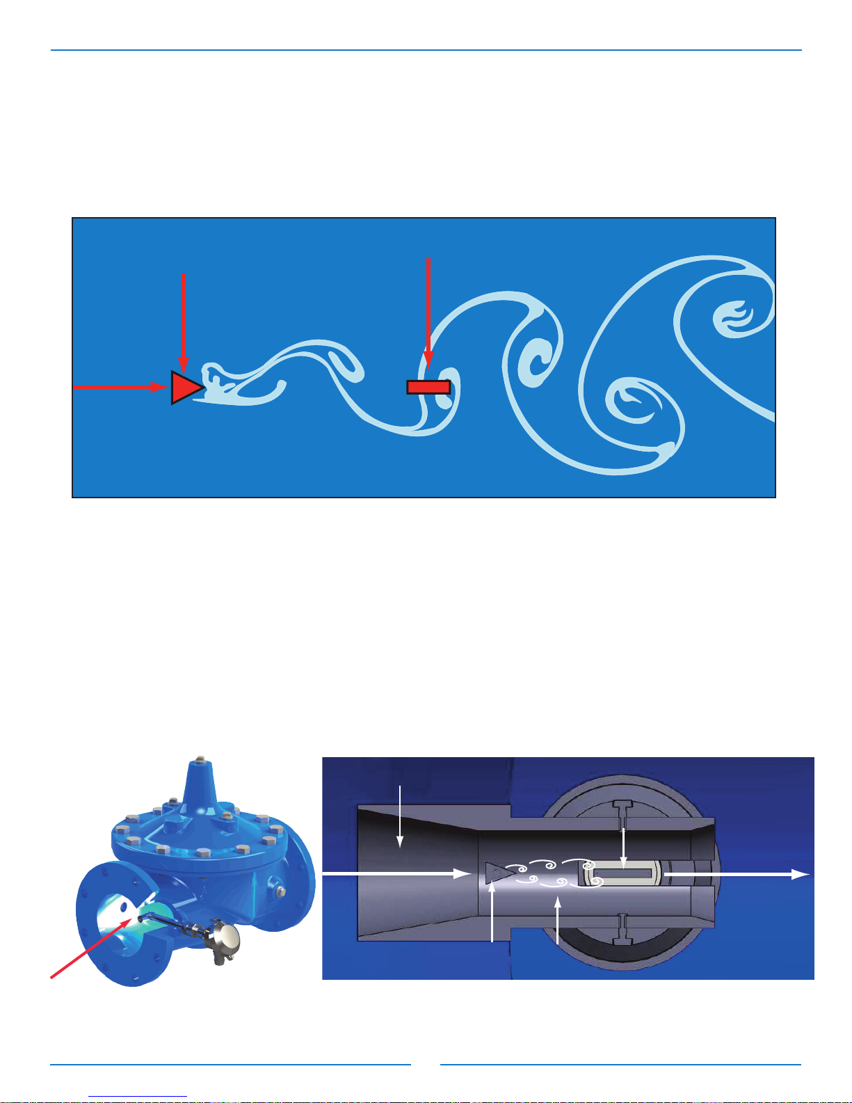
The X144D e- lowMeter is an insertion vortex flowmeter based on a phenomenon which generates of a
succession of alternating swirls called Karman vortex street ( igure 1-1).
When the fluid meets an obstacle (called a bluff body) which is placed in parallel with the flow of the fluid it
divides the flow and generates small swirls or vortices alternately on both sides downstream of the obstacle.
The generation of the swirls is directly proportional to the speed of the fluid. The detached swirls generate
zones of variable pressure that are detected by the forces acting on a small piezoelectric crystal
encapsulated in the transmitter ( igures 1-2 and 1-3).
The X144D e- lowMeter employs an innovative feature called the Swivel Measurement Cylinder which
allows for the proper distance between the bluff body and the sensor, while still retaining the capability of
being inserted into a tapping as small as 1/2-inch NPT.
Bluff Body
Sensor
Karman
Vortex
Street
Flow
Direction
Figure 1-1: Karman Vortex Street
Meter Bluff Body
Flow
Direction
Integral Sensor
Flow
Direction
Vortices
Measurement Cylinder
Figure 1-3
Figure 1-2
flow direction

6
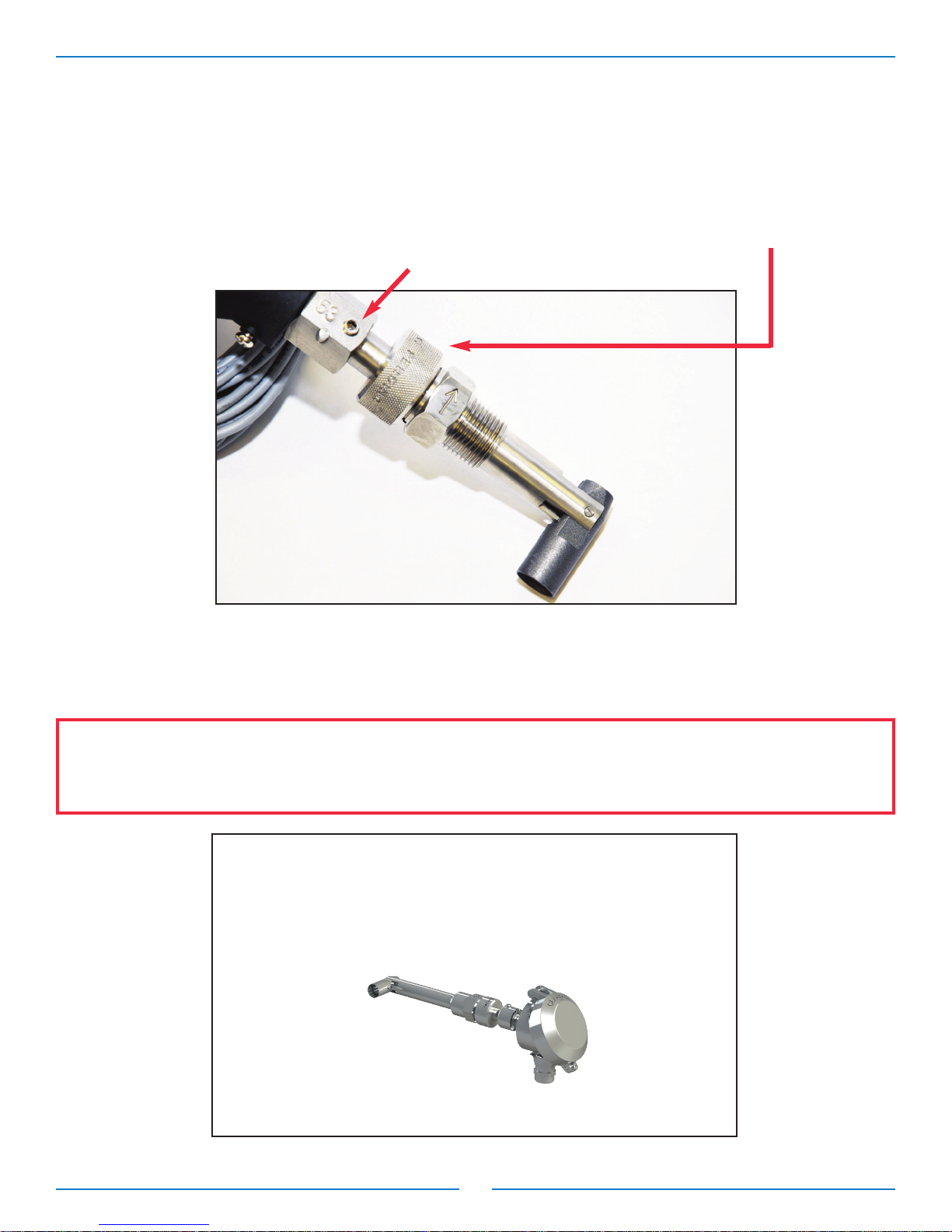
Figure 1-4: e-FlowMeter
X144D e-FlowMeter Parts
1) IP68 Submersible Electronics Housing 2) Knurled Lock 3) Centering Pin
4) O-Ring 5) Shaft 6) Sensor
1
2
6
53
Swivel Threaded nsert Parts
1) Straight Threads
2) Centering Groove
3) Tapered Threads
4) Sleeve
5) Swivel Measurement Cylinder
SECT ON 1: System Components and How They Work (continued)
1.2 – Supplied Parts List
X144D Equipment - Supplied by Cla-Val
1) e- lowMeter with Swivel Threaded Insert
( igures 1-4 and 1-5)
2) Insertion Tool ( igure 1-6)
3) 20 feet of Electrical Cable (See Section 2.5)
Figure 1-5: e-FlowMeter Swivel Threaded Insert Detail
X144D e- lowMeter
Swivel
Threaded Insert
4
1
3
4
2
5
Figure 1-6: Insertion Tool Kit
nsertion Tool Kit Parts
1) Bevel
2) Tool
3) Score Marks
4) Thumb Set Screw
5) Tool Lock
6) lat Tipped End
7) Locking Collar
1
4
2
53
6
7

7
SECT ON 1: System Components and How They Work (continued)
1.3 – Non-Supplied Parts List
The following parts are necessary for installation and operation but not included with the e- lowMeter:
• Cla-Val Automatic Control valve in which to insert the e- lowMeter - Globe or Angle Pattern, 2" - 36".
• Power supply
- 6-30 VDC, 0.7 Watts minimum
- Can be powered with batteries or AC/DC Converter
• Power supply/battery housing
with optional equipment to pair with
the X144D e-FlowMeter™
X144D e-FlowMeter Schematic
X144D
e-FlowMeter
Cla-Val Automatic Control Valve
6 - 30 VDC
Battery
SCADA
System
8
Section 2: nstallation of the X144D e-FlowMeter
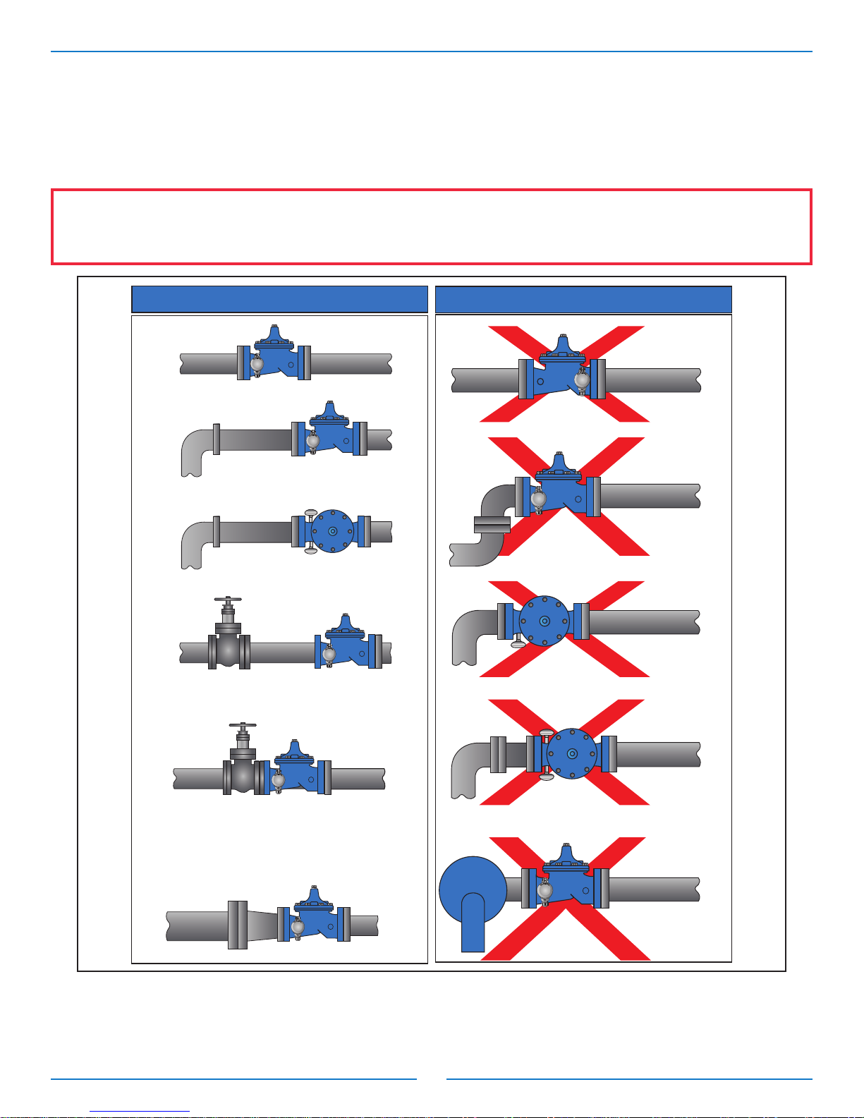
2.1 - nstallation Locations:
or optimum performance, it is recommended that the valve in which the X144D e- lowMeter is installed be
located as shown in the “Optimum Installations” illustration below, igure 2-1.
CAUT ON: Valves in which X144D e- lowMeters are installed MUST have upstream and downstream
Isolation Valves to ensure that the line is locked out and NOT under pressure during installation, maintenance
or removal of the X144D e- lowMeter.
pump
Unacceptable Installations
CLA-VAL
CLA-VAL
In Outlet Tapping
Downstream of
Double Elbow
Inside of
an Elbow
(top view)
1 to 5 Pipe
Diameters
Outside
or Inside
(top view)
On Discharge
of a Pump
CLA-VAL
pump
Optimum Installations
Downstream
of an Elbow
Pipe Reducer Upstream
> 5 Pipe Diameters
Either Inlet Tapping (top view)
(vertical rise)
CLA-VAL
CLA-VAL
In Inlet Tapping
CLA-VAL
CLA-VAL
Install Isolation Valve (any style) a minimum
of 5 pipe diameters upstream of the control valve
For installation directly onto the inlet flange of the
control valve or where less than 5 pipe diameters
upstream is the only option, an Isolation Valve MUST
be a ful ported, wide open Gate or Sluice style valve.
In this scenario, the Isolation Valve MUST NOT
be a Butterfly style valve.
CLA-VAL
Note: Do not use with 40 Series Rate-of- low Controllers with orifice on inlet
Do not use butterfly valves adjacent to X144D installations
Figure 2-1: nstallation Guidelines

9
Section 2: nstallation of the X144D e-FlowMeter (continued)
2.2 - Materials Required for nstallation
nsertion tool
• Tool allows the proper installation and alignment of the
bluff body to be parallel to upstream flow, ( igure 1-5).
Power Supply
• 6-30 VDC, 0.7 Watts minimum. If more than one piece of equipment will be connected to
this power supply, you must verify that the power supply is large enough to handle all the power needs of
the entire system, not just the X144D e- lowMeter.
• You will also need the appropriate equipment to connect the X144D to each the power supply. See your
local electrical specifications to determine the appropriate wire and connection hardware.
Pipe and Fittings Mounting Hardware
• The X144D connects directly into the control valve on an inlet port and the size of the thread is dependent
on the specific valve size for which it it has been calibrated - no additional fittings are required.
Cabling
• The X144D has 30 feet cable supplied and attached as a factory standard. If additional lengths of cable
are
needed, the connections should be made with #22 AWG or larger cable and may need to be shielded in
some environments where high electrical noise may exist. If using shielded cable, one end of the shielding
should be connected to an earth ground, such as a piping system fitting, etc.
CAUT ON:
• In all cases, installation should be done by qualified mechanical or electrical personnel.
Figure 1-5: Insertion Tool
Log-on to www.cla-val.com
and to learn more about Cla-Val’s
complete line of automatic control valves
10
Section 2: nstallation of the X144D e-FlowMeter (continued)
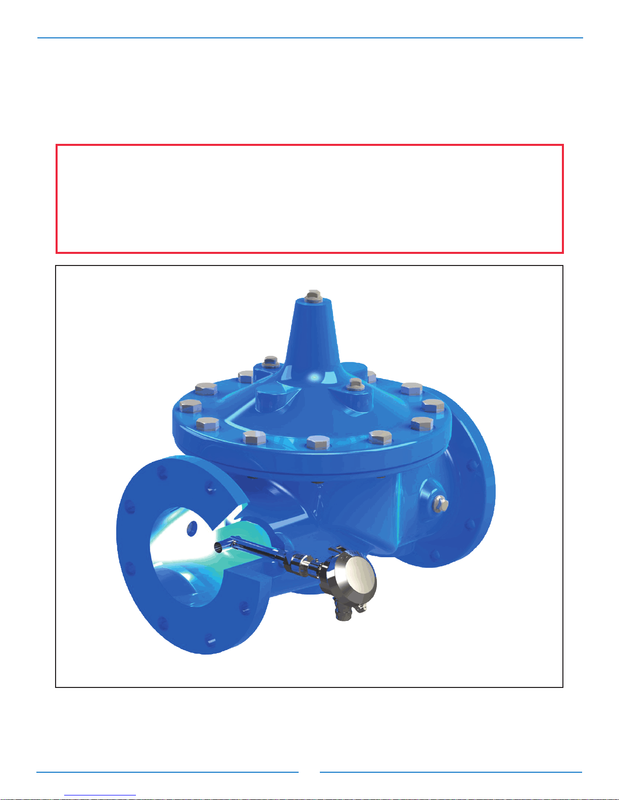
2.3 - Mounting the X144D e-FlowMeter
Mount the X144D e- lowMeter in a proper orientation as shown in igure 2-2.
NOTE:The X144D e- lowMeter may be installed in inlet tap of either side of the
Cla-Val Automatic Control Valve.
CAUT ON: ailure to install the unit correctly could result in faulty operation and/or damage
to the unit.
Figure 2-2: X144D e-FlowMeter correctly installed in a Cla-Val Control Valve

11
Section 2: nstallation of the X144D e-FlowMeter (continued)
2.4 - Step-by-Step nstructions: Mechanical nstallation
CAUT ON: BE ORE removing pipe plug, make sure that the pressure in the valve has been bled
off to prevent injury to personnel or damage to non-waterproof equipment
1) Isolate valve/pipe from pressure and flow.
2) Remove pipe plug on INLET boss of valve.
3) Remove sensor/head unit from threaded pipe insert
by unscrewing the knurled lock and sliding the sensor
out of the threaded insert ( igure 2-3).
Set aside sensor head, making sure to protect the
sensor tip
4) Apply Teflon®thread tape and/or pipe thread compound to tapered threads on pipe insert,
shown below ( igure 2-4):
5) Straighten the Measurement Cylinder by hand to create a slight angle ( igure 2-5); Tighten the
locking collar on the straight threads of the insert (2); and tighten the thumb
set screw (3); to maintain the slight angle of the Measurement Cylinder.
Figure 2-3
Figure 2-4
Figure 2-5
1 2 3
12
Section 2: nstallation of the X144D e-FlowMeter (continued)
2.4 - Step-by-Step nstructions Mechanical nstallation
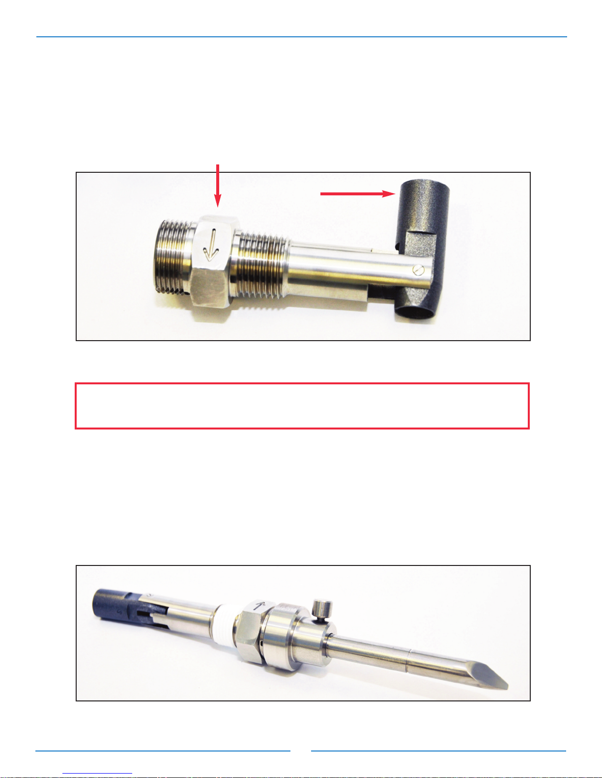
6) Screw threaded insert into the inlet tap of the control valve, tighten properly and align so that the
arrow points to downstream flow making sure that the wrench flat with arrow is level with the
valve cover,and the measurement cylinder is facing (parallel to) upstream flow. ( igure 2-6).
7) Measurement Cylinder Swivel Procedure
a) Position of Threaded Insert + Insertion Tool, just prior to installation into valve, ( igure 2-7).
b) Slide Insertion Tool straight out, then insert the opposite side flat tipped end into the
threaded insert.
c) Insert tool, flat tipped end first, making sure to feel for the Insertion Tool to engage the
measurement cylinder, then push straight into the insert until the tool seats, which puts
the measurement cylinder to roughly 90° to the sleeve of the threaded insert (see igure 2-8).
d) It may help to wiggle the tool slightly while pushing firmly.
Figure 2-6
Figure 2-7
Please note that the flat with the engraved arrow must be positioned so that arrow
is in line with the flow direction. Failure to do so will result in inaccurate readings.

13
Section 2: nstallation of the X144D e-FlowMeter (continued)
2.4 - Step-by-Step nstructions Mechanical nstallation
8) Once the measurement cylinder rotates, remove the tool lock then use the score marks on
the Insertion Tool to verify measurement cylinder is locked in 90° orientation, ensure that
the tool seated to appropriate ½” or ¾” score marks, ( igure 2-9).
9) Insert sensor into threaded pipe insert. Ensure that the centering pin is aligned
with the centering groove on the threaded insert, ( igure 2-10). Push firmly to
seat the o-ring.
Figure 2-9
Figure 2-10
pressure
Measurement
Cylinder swivels
to proper
position
Figure 2-8
replace this
photo with one
showing pin &
groove
14
Section 2: nstallation of the X144D e-FlowMeter (continued)
2.4 - Step-by-Step nstructions Mechanical nstallation
10) Ensure that the e- lowMeter is properly seated and tight using the knurled lock, hand tight only,
( igure 2-11). Tighten M3 Allen set screw to lock orientation of head.
Figure 2-11
Log onto www.cla-val.com
and click on the X144D e-FlowMeter icon to
learn more
CAUT ON: If the e- lowMeter is not properly seated, it will not hold pressure and will leak. To avoid
potential damage from water leaking at the tap, be sure that the e- lowMeter is tight and
seated.

15
Section 2: nstallation of the X144D e-FlowMeter (continued)
2.5 - Step-By-Step nstructions: Wiring Diagrams
X144D
e-Flow Meter
Required:
6 - 30 VDC,
Power Supply
Optional:
Pulse
grey
pink
red
blue
Pulse Output
Circuit Wiring
white
brown
4-20mA Loop
Power
Circuit Wiring
Optional:
4-20mA signal is passive.
Must be powered by 6-30 VDC
power supply/battery.
Figure 2-12:
X144D e-FlowMeter Wiring Overview

16
Section 2: nstallation of the X144D e-FlowMeter (continued)
2.5 - Step-by-Step nstructions: Wiring Diagrams
1) Connect V+ and V- wires to 6-30 VDC power source
2) Connect the wires marked 4-20mA (+/-) to the proper recording/measurement device. Connect device
per manufacturer’s recommendations.
3) If possible, use handheld multi-meter to verify mA readings prior to leaving installation.
a) When there is no flow present, the X144D e- lowMeter should read very close to 4.0 mA.
Note: AC/DC converters must be properly grounded in order to prevent electronic noise.
6-30 VDC
white wire
4-20mA
brown wire
4-20mA signal is passive.
Must be powered by 6-30 VDC
power supply/battery.
Note: When connecting 4-20mA
circuit, place all reading/ logging
equipment (if any) in series
X144D e-FlowMeter™
SCADA
System
Key: accessory equipment not supplied with e-FlowMeter
red
blue
grey
pink
white
brown
6 - 30 VDC
Power Supply/Battery
Figure 2-13: X144D e-FlowMeter
using 4-20mA Output

17
Section 2: nstallation of the X144D e-FlowMeter (continued)
2.5 - Step-by-Step nstructions: Wiring Diagrams
1) Connect V+ and V- wires to 6-30 VDC power source
2) Connect the wires marked pulse (+/-) to the proper recording/measurement device. Connect device per
manufacturer’s recommendations.
Note: AC/DC converters must be properly grounded in order to prevent electronic noise.
X144D e-FlowMeter™
Key: accessory equipment not supplied with e-FlowMeter
red
blue
grey
pink
white
brown
6 - 30 VDC
Power Supply/Battery
SCADA
System
Figure 2-14: X144D e-FlowMeter
using Pulse Output

18
Section 2: nstallation of the X144D e-FlowMeter (continued)
2.6 - Wiring nstallation
Power
Connections
4-20mA
Connections
Red
6-30 VDC
Blue
0 VDC
DIP
Switch 2
ON
White
PO1
Brown
AI2+
4-
Figure 2-15:
Wiring Diagram: X144D e-FlowMeter
with VC-22D Controller (4-20mA Output)
Power
Connections
Pulse
Connections
Red
6-30 VDC
Blue
0 VDC
Pink
0V
Gray
DI1
Figure 2-16:
Wiring Diagram: X144D e-FlowMeter
with VC-22D Controller (Pulse Output)

19
SECT ON 3: X144D e-FlowMeter Operation
3.1 – Startup Checklist
ollow this procedure when starting the installation for the first time or after shutting the system down for
maintenance of the Control Valve.
1) Check all connections to power supply and other User Devices (data loggers, telemetry, etc.)
2) Ensure all wiring is properly connected per wiring diagrams.
3) Open shut-off valves and allow water into the system.
4) Check the system for water leaks, at both the tapered threads, as well as the straight threads
with knurled lock.
5) Check surrounding piping and auxiliary equipment for leaks.
6) Verify X144D is configured to correct valve size.
7) Verify mA scaling between X144D and PLC/display match. (per table 1):
Table1: X144D e-FlowMeter Analog Range (4-20mA Scaling)
Log onto www.cla-val.com
and click on the X144D e-FlowMeter
icon to learn more
*2" X144D e- lowMeter may be installed on new valves only
Note: Consult actory for Angle Pattern Applications
Port Style Line Size
inches (mm)
**2"
(50)
(100-49
Body)
2-1/2"
(65)
3"
(80)
4"
(100)
6"
(150)
8"
(200)
10"
(250)
12"
(300)
14"
(350)
16"
(400)
18"
(450)
20"
(500)
24"
(600)
30"
(750)
Full Port
Valves
4mA = 0
(GPM -
l/s)
20mA Range
(GPM) 260 375 575 1000 2250 3900 6000 8750 10500 14000 17500 22000 31000 52000
20mA Range
(l/s) 16.4 23.7 36.3 63.1 142 246 379 552 663 883 1104 1388 1956 3281
Full Port
Pulse
Weight*
Gal/Pulse 1 1 1 1 1 1 1 2 2 3 3 4 6 9
l/Pulse 0.63 0.63 0.63 0.63 0.63 0.63 0.63 0.13 0.13 0.19 0.19 0.25 0.38 0.57
Reduced
Port
Valves
4mA = 0
(GPM-
l/s)
20mA Range
(GPM)
not available
675 1600 2900 4500 5650 7750 9350
Consult Factory
20mA Range
(l/s) 42.5 101 183 284 356 489 590
Reduced
Port
Valves
Pulse
Weight*
Gal/Pulse 1 1 1 1 1 2 2
l/Pulse 0.63 0.63 0.63 0.63 0.63 0.13 0.13

20
SECT ON 3: X144D e-FlowMeter Operation
3.2 – Shutdown/Removal of X144D e-FlowMeter
1) Close the shut-off valves to stop the flow of water, bleed pressure.
2) Disconnect all wiring.
3) ollow the steps below to remove the X144D e- lowMeter
from the Control Valve.
a) Unscrew knurled lock and remove the sensor from the
threaded insert and set aside, making sure to protect the sensor tip.
b) Orient the Insertion Tool so that the bevel is facing downstream, away from the centering groove,
and insert into the threaded insert.
c) The tool will engage the top face of the measurement cylinder and force it to the 45° position,
as shown below.
CAUT ON 1: ailure to use
the provided Insertion Tool
W LL result in damage to
the e- lowMeter
CAUT ON2: To avoid injury,
isolate the valve and bleed
pressure prior to removing
the e- lowMeter
remove
insert and apply light force
Figure 3-1
Figure 3-2
Figure 3-3
Other manuals for X144D e-FlowMeter
2
Table of contents
Other CLA-VAL Measuring Instrument manuals


