CLA-VAL VC12 Programming manual

Hardware
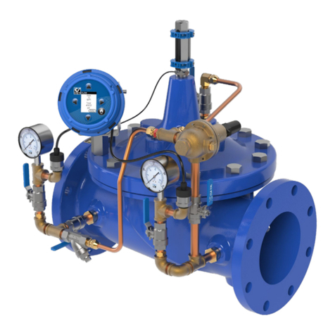
VC12 Assembly X-143MP & CVM-33 Assembly
CPM Assembly
X143MP
CPM pilot
3-Way valve
X43 Strainer
CLA-VAL VC12
Quick Start Instructions
Visit www.cla-valpacic.com for more details. Contact the Factory at info@cla-valpacic.com 1

Visit www.cla-valpacic.com for more details. Contact the Factory at info@cla-valpacic.com 2
Mounting Instructions
Install the VC12 on the wall
a) Fix the wall-mounting plate with the provided screws
b) Mount the VC12 on the wall-mount fixing plate
c) Secure with the wing nuts provided
IMPORTANT!
For communicating devices, if the antenna is plugged directly
on the device (without extension lead), please ensure that the
VC12 is mounted vertically with the USB and antenna connectors
on the top.
The connection to the VC12 controller is made via circular plug
connectors which are pre-wired, therefore no internal wiring is
necessary. Each connector has a pre-defined function which
only allows the relevant component to be connected (dedicated
connectors).
1
3
4Connect the various elements to the VC12
VC12 controller packaging
delivered with accessories
a)
b)
c) Antenna
USB
Flow: Flowmeter connection
P1: Inlet pressure sensor connection
P2: Outlet pressure sensor connection
e-Power MP : e-Power X-143MP/2MP turbine connection
3
4
15
6
2
1. Wall-mount fixing bracket
2. VC12 controller
3. Magnetic stick
4. Calibration certificate and
USB stick
5. Antenna (optional)
6. Pressure sensor(s)
ratiometric
a) To run the VC12, connect the e-Power-MP connector
or the start key on socket (a)
b) When the connector above is connected,
the VC12 is powered (internal battery is activated)
c) When the connector is removed from socket (a),
the VC12 is disabled (internal battery is de-activated)
d) IMPORTANT!
To access the internal USB port, perform operation in a dry
and clean environment. If not possible, make sure that no
humidity or dust enters the device.
2
Run the VC12
d)
(a)

Visit www.cla-valpacic.com for more details. Contact the Factory at info@cla-valpacic.com 3
Laptop Wifi pairing and parameters
6-24 VDC IN: External power supply connection
2: Solenoid #2 output connection
1: Solenoid #1 output connection
CVP/CVM: CVP/CVM actuators connection
e-Lift: CLA-VAL valve position sensor connection
I/O:General Input/Output signal connection
a:CLA-VAL Antenna connection
b:USB-A port connection
a) b)
2 Activate the VC12 controller
Hold the magnetic stick over the button of the VC12
(approximately 5 seconds) until a green light flashes.
Check that the Wifiicon is present in the toolbar of your
computer. If not, please refer to the user manual of your
computer to activate the Wifiinterface.
1 Activate the Wifiinterface on the computer
3 Display the list of Wifidiscovered devices on your
computer
a) Click on the Wifi icon and select the VC12 in the devices list for
connection via Wifi.
b) Enter the Wifi security key shown on the VC12 OLED display to
allow Wifi Peering to the VC12 controller.
a)
b)
VC12-Loic
VC12-Loic
5

Visit www.cla-valpacic.com for more details. Contact the Factory at info@cla-valpacic.com 4
Mobile Wifi pairing and parameters
a) Launch a VNC viewer (for instance TightVNC Viewer).
b) Enter the IP address shown on the VC12 OLED screen in the
VNC viewer application.
c) Establish the connection.
d) Enter the password shown on the VC12 OLED screen in the
second screen of VNC viewer application.
Check that the Wifiicon is displayed in the toolbar of your
mobile. If not, please refer to the user manual of your mobile to
activate the Wifiinterface.
4 Connect to the VC12 controller
2 Activate the VC12 controller
1 Activate the Wifiinterface on the mobile device
b) Click on the Wifi icon and select the VC12 in the devices list for
connection via Wifi.
a)
3 Display the Wifidiscovered devices on your mobile
Hold the magnetic stick over the button of the VC12
(approximately 5 seconds) until a green light flashes.
VC12-Loic
VC12-Loic

Visit www.cla-valpacic.com for more details. Contact the Factory at info@cla-valpacic.com 5
You are connected on VC12.
4 Connect to the VC12 controller
b) Enter the Wifi security key shown on OLED display to allow Wifi
peering to the VC12 controller.
b)
b)
c)
a) Launch a VNC viewer (for instance VNC Viewer).
b) Create a new connection & enter the IP address and
password shown on the VC12 OLED screen in the VNC
viewer application.
c) Launch the connection and click OK for unencrypted
connection, then Introduce the password shown on the VC12
OLED screen in second screen of VNC viewer application.
VC12-Loic
VC12-Loic
VC12-Loic
VC12-Loic

Visit www.cla-valpacic.com for more details. Contact the Factory at info@cla-valpacic.com 6
1VC12 commissioning
2VC12 in service
b) 1st battery connection or VC12 in standby mode
(OLED display off): upper LED stays green and
lower LED blinks green during system boot up
(OLED display and Bluetooth activation).
a) Wake up the OLED display and establish
Bluetooth communication, or put the device in
standby mode, by holding the magnet stick on the
symbol for 5 seconds (lower LED (1) remains
Green) until the upper LED (2) blinksGreen once.
c)
After the VC12 commissioning is completed, the
OLED display is off. Lowest LED flashes green
every 10 seconds
.
d) During data transfer, the OLED display and
magnetic contacts are disabled (not possible to
wake-up display).
Lowest LED flashing red (slight flashing red on
upper LED.
2) 1 x blinking
Green LED
1) 5 sec Fixed
Green
Fixed Green
Blinking Green
Off
Blinking green
every 10 seconds
Slight Red
blinking
Blinking red
Once
commissioned
Data transfer
1st Connection
or Standby
Wake-up
LED Diagnostics
IMPORTANT!
Disconnect the CVM actuator from the VC12 controller
before calibrating the CPM pilot. Please refer to the
dedicated CPM document for its adjustment.
1Auto mode: The CPM hydraulic pressure
reducing pilot setting is controlled by the
CVM actuator.
2Manual mode: The CVM actuator is
isolated from the CPM hydraulic pressure
reducing pilot. Outlet pressure returns to
the lower Pressure setting of the CPM
pilot.
Auto Mode or Manual Mode Settings
(
2
F
)
(
2G
)
(
2
F
)
(
2
G
)
Open ball valve (2F)
Close ball valve (2G)
Close ball valve (2F)
Open ball valve (2G)

pressure until the pressure is a minimum
Initial setting
1) Low pressure adjusting screw must be fully
screwed in.
2) 3-Wayvalve handle must point towards the red
tube (connected from the Inlet pressure)
: Remove air from bias chamber of the
modulation pilot using the bleed screw (5).
HIGH PRESSURE limit PH
ADJUSTMENT
3) Adjust the high pressure hydraulic limit PHin
dynamic conditions with the high-pressure
adjusting screw
: The setting should be min. 2mhd higher
than your programmed profile.
LOW PRESSURE limit PLADJUSTMENT
4) Close 3-Way valve asillustrated.
5) Adjust the low pressure hydraulic limit PLunder
flowing conditions with the low-pressure
adjusting screw using the screwdriver provided.
Access is via the hole in the high pressure
adjusting screw. Slowly unscrew (anti-clockwise)
the low pressure adjusting screw to adjust low
PL
2mhd below the minimum programmed profile.
: During this adjustment, ensure that the main
valve is under flow conditions.
: Do not apply any force on the low pressure
adjusting screw as this will affect outlet pressure
during adjustment.
Electronic operation (Auto)
6) Turn the 3 -Way valve handle towards the Green
tube (connected to the CVM Motor)
1)
3)
PH
5)
CPM Pilot Adjustment
PACIFIC
AUTOMATIC CONTROL VALVES
45 KENNAWAY ROAD
WOOLSTON
CHRISTCHURCH 8023
!"#$%#"&
#'()*+(,-&!).(/)0&%+0123&4)/&5).6&7,00,.8
!"#$%#"&'#()*)(
+,&-.//#0#1 23#45&633"783/5&!9:)78(9;:(95&<.0&=.#"#/4
>."?&@A+&BCDE&FA+&+GAC
H$I#)"?J#(7#".7K("#$L#"M(3N
6?&000M("#$L#"J#()*)(M(3N
Cla-Val Pacic
45 Kennaway Road, Woolston, Christchurch
Tel: +64 (0)3 964 4860
Email: aspacsales@cla-val.com
www.cla-valpacic.com
!"#$%#"&
#'()*+(,-&!).(/)0&%+0123&4)/&5).6&7,00,.8
7
Other manuals for VC12
1
This manual suits for next models
2
Table of contents
Other CLA-VAL Measuring Instrument manuals
Popular Measuring Instrument manuals by other brands
ILX Lightwave
ILX Lightwave LDX-32420 user guide
Hanna Instruments
Hanna Instruments HI98198 OPDO instruction manual
Endress+Hauser
Endress+Hauser Micropilot II manual
Velleman
Velleman DVM8681 user manual

York Survey Supply
York Survey Supply 354420 operating instructions
SIGLENT
SIGLENT SSA3000X Plus quick guide
