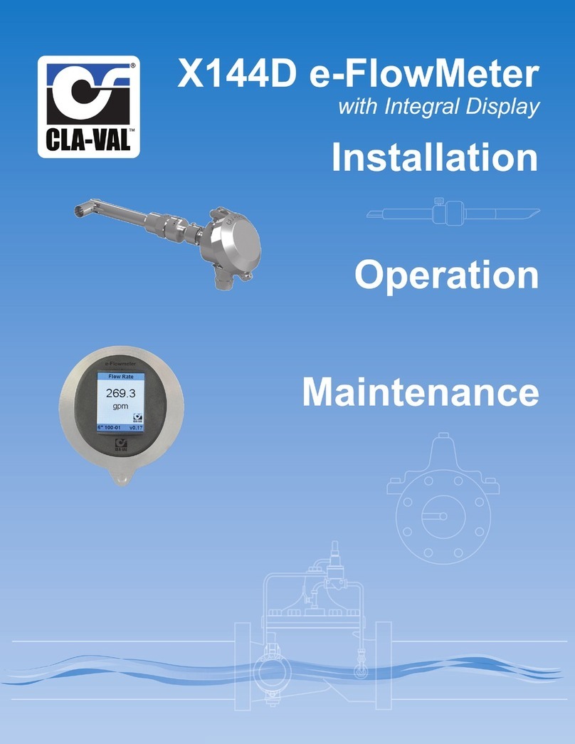
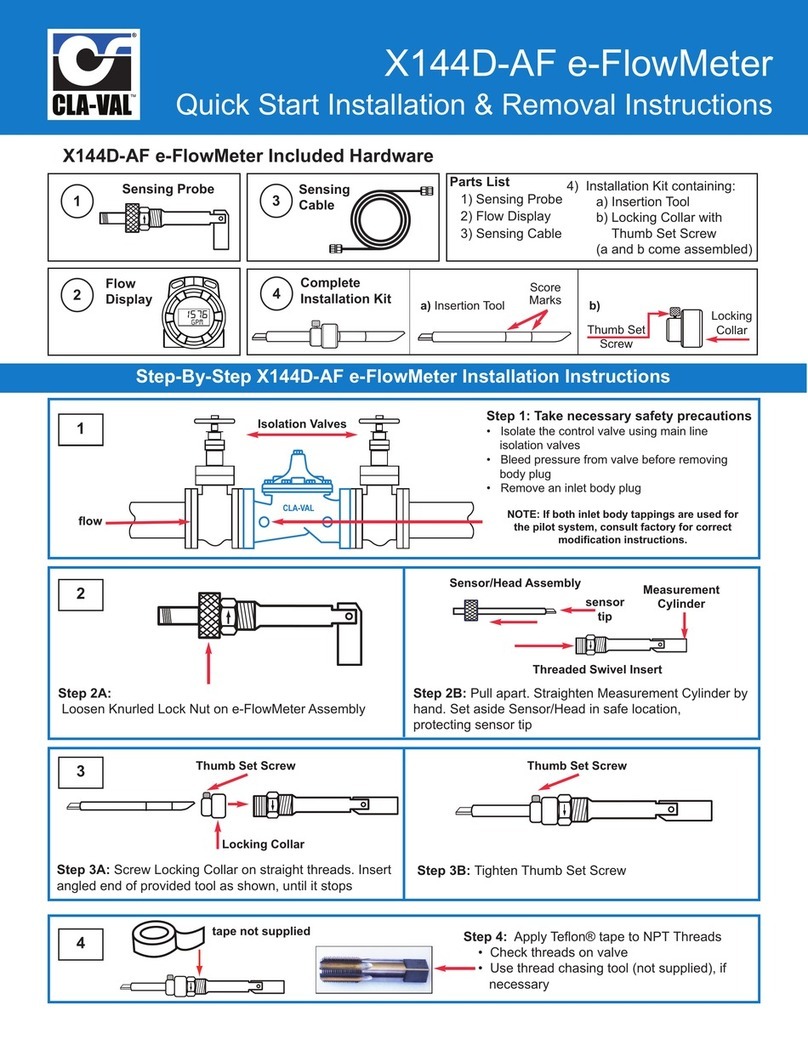
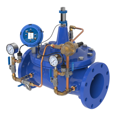
CLA-VAL e-FlowMeter User manual

CLA-VAL e-FlowMeter
Vortex Flow Meter
CLA-VAL Europe www.cla-val.ch [email protected] 1-LIN041UE C 11/20
© Copyright CLA-VAL Europe - Specifications subject to change without notice - no contractual illustrations. Reduce your waste - Sort your rubbish
User Manual

CLA-VAL e-FlowMeter
Vortex Flow Meter
CLA-VAL Europe www.cla-val.ch [email protected] 2-LIN041UE C 11/20
© Copyright CLA-VAL Europe - Specifications subject to change without notice - no contractual illustrations. Reduce your waste - Sort your rubbish
Table of Contents
1Introduction........................................................................................................................ 3
1.1Precautions Before Starting ......................................................................................................3
1.2Default Calibration and Set Time ..............................................................................................3
1.3General Disclaimer ...................................................................................................................3
1.4Environmental Protection..........................................................................................................3
1.5Typography...............................................................................................................................3
2Operation of the e-FlowMeter ...........................................................................................4
3Installation of the e-FlowMeter .........................................................................................6
3.1Installation Locations ................................................................................................................6
3.2Installation Instructions .............................................................................................................7
3.3Installation and Removal...........................................................................................................7
3.3.1Materials Required for Installation .....................................................................................................7
3.3.2Installation..........................................................................................................................................8
3.3.3Removal Instructions .......................................................................................................................10
3.3.4e-FlowMeter Wiring..........................................................................................................................12
4Specification ....................................................................................................................13
4.1Calibration...............................................................................................................................13
4.2Technical Data........................................................................................................................13
4.3Flow Parameters Factory Calibrated ......................................................................................14
4.4Dimensions .............................................................................................................................14
5Maintenance and Repair .................................................................................................15
5.1Routine Maintenance..............................................................................................................15
5.2Cleaning Debris from Measurement Cylinder .........................................................................15
5.3Dealing with Sensor Tip Damage ...........................................................................................15
6Software and Firmware ...................................................................................................16
6.1Connexion PC / e-FlowMeter..................................................................................................16
6.2Firmware Update (Internal Software)......................................................................................17
6.34-20 mA, Pulse and Pulse Digital Ouput Configuration ..........................................................19
6.4Calibration...............................................................................................................................20

CLA-VAL e-FlowMeter
Vortex Flow Meter
CLA-VAL Europe www.cla-val.ch [email protected] 3-LIN041UE C 11/20
© Copyright CLA-VAL Europe - Specifications subject to change without notice - no contractual illustrations. Reduce your waste - Sort your rubbish
1 INTRODUCTION
1.1 PRECAUTIONS BEFORE STARTING
Before use, please connect to our webside www.cla-val.ch to:
Download and install the USB driver on your PC [Refer to the driver USB installation manual (LIN006UE)]
Download and install the latest version of the product software on your PC
Check that the product has the latest firmware version
1.2 DEFAULT CALIBRATION AND SET TIME
: By default, the e-FlowMeter is factory calibrated according to the DN and the valve model requested see chapter 4.3
« Flow Parameters Factory Calibrated ». But it is possible to change some parameters, for examples values of the 4 mA,
20 mA, pulse weight and pulse width by using the e-FlowMeter Software available on our website www.cla-val.ch
1.3 GENERAL DISCLAIMER
In accordance with our policy of continuous development and improvement, CLA-VAL Europe reserves the right to modify or
improve these products at any time without prior notice. CLA-VAL Europe assumes no liability or responsibility for any errors
or omissions in the content of this document.
1.4 ENVIRONMENTAL PROTECTION
Help to preserve and protect the environment. Recycle used batteries and accessories.
1.5 TYPOGRAPHY
Throughout this manual, following typographical conventions and symbols have been adopted to help readability:
a. "Bold":Menu, command, tab and button.
b. BOLD ITALIC: Important information.
c. (1): Reference numbers of images.
d. www.cla-val.ch: Internet address.
e. : Some tips.
f. : Warning!

CLA-VAL e-FlowMeter
Vortex Flow Meter
CLA-VAL Europe www.cla-val.ch [email protected] 4-LIN041UE C 11/20
© Copyright CLA-VAL Europe - Specifications subject to change without notice - no contractual illustrations. Reduce your waste - Sort your rubbish
2 OPERATION OF THE E-FLOWMETER
The CLA-VAL e-FlowMeter is a vortex shedding insertion flow meter designed to be factory assembled or retrofitted into a
CLA-VAL Automatic Control Valve to provide accurate flow measurement data without the need to install a separate meter.
Configured to be installed in the inlet tapping of a CLA-VAL Automatic Control Valve, the e-FlowMeter can be used in valves
directly downstream of a turbulent flow such as elbows, valves or reducers. The e-FlowMeter employs an innovative and
patented swivel mechanism allowing the meter to be inserted into tappings as small as 1/2".
The e-FlowMeter measures and transmits flow information as a 4-20 mA signal, digital pulse or pulse. It can be directly
connected to a SCADA system, various market loggers or products in the CLA-VAL e-Line range.
e-FlowMeter
See chapter 3 «Installation of the e-FlowMeter» for installation
CLA-VAL valve
e-FlowMeter
Electronic housing
Power supply and
signal output
Piezoelectric
sensor
Insert

CLA-VAL e-FlowMeter
Vortex Flow Meter
CLA-VAL Europe www.cla-val.ch [email protected] 5-LIN041UE C 11/20
© Copyright CLA-VAL Europe - Specifications subject to change without notice - no contractual illustrations. Reduce your waste - Sort your rubbish
Karman Vortex Street
The e-FlowMeter is a vortex shedding insertion flow
meter, based on the phenomenon of generating an
alternating series of vortices called «Karman vortex
street».
When the fluid encounters an obstacle placed in the
axis of fluid flow, it divides and creates small vortices
alternating on either side downstream of the obstacle.
The frequency of vortex shedding, or generation of
vortices is directly proportional to fluid velocity. These
detached vortices generate variable pressure zones
that are detected in the form of short bursts of
pressure, using a measuring sensor placed
downstream of the obstacle.
Frequency measurement
The frequency of pressure surges or generation of vortices is
counted using a piezoelectric crystal encapsulated in the
sensor head. The latter is connected by 2 wires to the circuit
board for signal processing.
Measurement cylinder orientation
Upon insertion of e-FlowMeter in the valve, the measurement
cylinder is oriented parallel to the direction of flow. After
inserting the CLA-VAL tool which allows 90 degree rotation of
the measurement cylinder, it is locked in position by the
piezoelectric sensor insert. This unique 90 degree swivel
mechanism makes it possible to increase the length of the
measurement cylinder up to 40 mm allowing stabilization of
the fluid. This unique design allows it to be inserted into a
valve body tapping of ½".
Signal processing and output information
Existing Vortex flow meters operate in turbulent steady
flow defined by a Reynolds number exceeding 5’000.
This flow regime establishes stable and easily
detectable «Karman vortex street» using
unsophisticated electronics. Velocities are detected, in
general, above 0.5 m/s.
Through the innovative electronic card developed by
CLA-VAL, e-FlowMeter can measure flow from a
velocity of 0.1 m/s to obtain an accurate signal. This is
then converted to 4-20 mA, pulse or digital pulse to suit
the desired application.
Bluff body Piezoelectric
sensor The path of the
Karman Vortex street
Printed Circuit Board
Piezoelectric
sensor
Measurement
cylinder
Insert
Bluff body
Flow direction

CLA-VAL e-FlowMeter
Vortex Flow Meter
CLA-VAL Europe www.cla-val.ch [email protected] 6-LIN041UE C 11/20
© Copyright CLA-VAL Europe - Specifications subject to change without notice - no contractual illustrations. Reduce your waste - Sort your rubbish
3 INSTALLATION OF THE E-FLOWMETER
3.1 INSTALLATION LOCATIONS
Optimum Installations Unacceptable Installations
In Inlet Tapping In Outlet Tapping
Downstream of an Elbow (Vertical rise) Downstream of double Elbows
(Directly) Ouside Elbow Inside of an Elbow
> 5 Pipe Diameters 1 to 5 Pipe Diameters
Directly upstream of a CLA-VAL H-Strainer (1)* On discharge of a Pump
Pipe Reducer Upstream
*(1) Needs a special calibration, contact CLA-VAL

CLA-VAL e-FlowMeter
Vortex Flow Meter
CLA-VAL Europe www.cla-val.ch [email protected] 7-LIN041UE C 11/20
© Copyright CLA-VAL Europe - Specifications subject to change without notice - no contractual illustrations. Reduce your waste - Sort your rubbish
3.2 INSTALLATION INSTRUCTIONS
1- All installations, adjustments and maintenance should be carried out by a competent person.
2- Do not exceed the maximum ratings given in the specifications and printed on the label.
3- The electrical connections should be made as described in the user’s manual.
4- Before all maintenance operations, shut down the power supply.
: DO NOT ATTEMPT TO OPEN THE PRODUCT AS THIS WILL INVALIDATE THE WARRANTY!
3.3 INSTALLATION AND REMOVAL
3.3.1 MATERIALS REQUIRED FOR INSTALLATION
3.3.1.1 Insertion Tool
The insertion tool is not provided with the e-FlowMeter.
The insertion tool is needed for the installation and removal of the e-FlowMeter in a CLA-VAL valve. It allows the rotation of
the measurement cylinder in the right position.
The insertion tool with a length of 165 mm is used for e-FlowMeter sizes 1,2a and 2b, the insertion tool with a length of
368 mm is used for e-FlowMeter sizes 3 and 4.
3.3.1.2 Power supply for pulse and digital pulse output
There are 2 ways to power the e-FlowMeter for the pulse output. The first is 5 VDC, the second is 6-24 VDC with stabilized
power supply, battery, turbine e-Power MP or IP. 3 mA minimum are required (see schematic chapter 3.3.4).
3.3.1.3 Power supply for 4-20 mA output
The voltage needed is 8 - 32 VDC, 20 mA minimum are required. Take care that the loop is closed to obtain a signal
4-20 mA.
3.3.1.4 Cabling
The e-FlowMeter has a 3 or 10 meter cable with 12 wires of 0.22 mm
2
supplied and attached as a factory standard. If
additional lengths of cable are needed, the connections should be made with 0.22 mm
2
or larger wire and may need to be
shielded in some environments where high electrical noise may exist. If using shielded cable, one end of the shielding
should be connected to an earth, such as piping system fitting, etc.
Score marks
Locking collar
Insertion Tool Knurled screw

CLA-VAL e-FlowMeter
Vortex Flow Meter
CLA-VAL Europe www.cla-val.ch [email protected] 8-LIN041UE C 11/20
© Copyright CLA-VAL Europe - Specifications subject to change without notice - no contractual illustrations. Reduce your waste - Sort your rubbish
3.3.2 INSTALLATION
CARE OF THE EQUIPMENT!
The tip of the flow sensor is a precision-built part of the equipment and must be handled with care.
When the flow sensor is not installed, sensor must be protected by the yellow protection cap.
Physical damage to the flow sensor affects the performance and invalidates the warranty.
IMPORTANT !
a) Isolate the control valve using main line isolation valves.
b) Bleed pressure from the valve.
c) Remove body plug from valve inlet. If both inlet body
tappings are used for the pilot system, consult
CLA-VAL factory for correct modification instructions.
e-FlowMeter delivered in 2 parts: A and B
a) Straighten the measurement cylinder as illustrated (Fig.1).
b) Screw locking collar to the end of the swivel insert
assembly.
c) Insert angled end of the tool provided as shown, until it
stops. Then tighten knurled screw. Apply Teflon® tape to
threads of the insert.
a) Screw swivel insert into the valve and orient arrow marked
on the hexagonal section to point downstream and parallel
to the direction of flow.
IMPORTANT !
Swivel insert assemby must be parallel to the direction of
flow.
Inlet body tapping
1
2
3
4
Measurement cylinder
Swivel insert
Fig.2
Angled end
Fig.1
Sensor with
protective
cap
Sensor assembly
B
A
Mounting part A

CLA-VAL e-FlowMeter
Vortex Flow Meter
CLA-VAL Europe www.cla-val.ch [email protected] 9-LIN041UE C 11/20
© Copyright CLA-VAL Europe - Specifications subject to change without notice - no contractual illustrations. Reduce your waste - Sort your rubbish
a) Loosen knurled screw and remove locking collar from tool.
Remove tool and insert opposite end into the assembly.
(Fig.1 & 2)
b) Turn gently until tool engages. Then push firmly until score
mark is flush with the face of the swivel insert assembly.
(Fig.3)
a) Remove insertion tool. Remove the protection cap by
pulling upright. (Fig.1)
b) Reassemble e-FlowMeter by inserting the sensor assembly.
(Fig.2)
c) Guide for the pin is positioned in the groove as show.(Fig.3)
Fully engage the sensor assembly and tighten the knurled
nut. HAND TIGHT ONLY.
d) To orient the sensor assembly, loosen the headless screw
(Fig.3), orient the assembly as required then and tighten the
headless screw. Proceed in accordance with wiring
diagrams.
5
Fig.1
Fig.2
Fig.3
6
Fig.2
Fig.3
Pin
Headless screw
Fig.1
Mounting part B

CLA-VAL e-FlowMeter
Vortex Flow Meter
CLA-VAL Europe www.cla-val.ch [email protected] 10 -LIN041UE C 11/20
© Copyright CLA-VAL Europe - Specifications subject to change without notice - no contractual illustrations. Reduce your waste - Sort your rubbish
3.3.3 REMOVAL INSTRUCTIONS
IMPORTANT !
a) Isolate the control valve using main line isolation valves.
b) Bleed pressure from the valve before removing the
e-FlowMeter
c) Disconnect power to all electronic devices on valve,
including e-FlowMeter
a) Hand loosen the knurled lock from straight threads (Fig.1)
b) Remove the e-FlowMeter sensor / head assembly by pulling
straight outward (Fig.2), taking extra care to protect the
sensor tip.
1
2
Fig.1 Fig.2

CLA-VAL e-FlowMeter
Vortex Flow Meter
CLA-VAL Europe www.cla-val.ch [email protected] 11 -LIN041UE C 11/20
© Copyright CLA-VAL Europe - Specifications subject to change without notice - no contractual illustrations. Reduce your waste - Sort your rubbish
a) Orient the installation tool as shown on picture and insert
into the threaded swivel insert. (Fig.1)
b) Push the tool with light force to orient the measurement
cylinder. (Fig.2)
c) Slide installation tool straight out, then rotate 180° (Fig.3).
d) Push the tool to straighten the measurement cylinder, and
then secure the installation tool in place with locking collar
in locked position (Fig.4)
e) Unscrew and remove threaded swivel insert from the
valve tapping with the measurement cylinder
straightened.(Fig.5)
Insert body plug into tapping while servicing the
e-FlowMeter
3
Fig.4
Fig.5
Fig.3
Fig.1
Fig.2

CLA-VAL e-FlowMeter
Vortex Flow Meter
CLA-VAL Europe www.cla-val.ch [email protected] 12 -LIN041UE C 11/20
© Copyright CLA-VAL Europe - Specifications subject to change without notice - no contractual illustrations. Reduce your waste - Sort your rubbish
3.3.4 E-FLOWMETER WIRING
3.3.4.1 Standard wiring
3.3.4.2 Wiring example: 4-20 mA output

CLA-VAL e-FlowMeter
Vortex Flow Meter
CLA-VAL Europe www.cla-val.ch [email protected] 13 -LIN041UE C 11/20
© Copyright CLA-VAL Europe - Specifications subject to change without notice - no contractual illustrations. Reduce your waste - Sort your rubbish
4 SPECIFICATION
4.1 CALIBRATION
The e-FlowMeter is factory calibrated according to the part number. The calibration is specific to the type and size of the
valve. The calibration has been set according to the CLA-VAL IT050 quality test.
4.2 TECHNICAL DATA
Electrical Specifications
Power supply:
(recommended
CLA-VAL turbine power source)
4-20 mA Mode:
Voltage: 8-32 VDC (e-Power IP)
Consumption: 4-20 mA
Mode voltage pulse or digital pulse:
5 VDC (e-Power MP with super capacitor)
6 - 24 VDC
Consumption: 3 mA
Power protection:
Connection:
Repeatability:
4-20 mA Mode:
Over Voltage: max. 40 VDC
Inversion: max. 40 VDC
Pulse or Digital Pulse Mode:
a) Voltage 5 VDC:
Over Voltage: max. 5.5 VDC
Inversion: unprotected
b) Voltage: 6 - 24 VDC:
Over Voltage: max. 40 VDC
Inversion: max. 40 VDC
1 cable of 12 wires 0.22 mm2
< 1 %
Other Specifications
Valve size and model: (mm) NGE 65 - 600 / GE 65 - 400 (Note: NGE 65 and NGE 80 factory tapped ½")
Operating pressure: PN 25 bar standard
Temperature range: - 10°C to + 80°C (electronics only)
Protection: IP68
Software interface:
Calibration
Plug & Play / NT / 2000 / XP / Vista / Win 7 (32 & 64 bit)
Factory standard
Default Modes
Loss of signal: After 30 seconds (default), the 4-20 mA signal is 4 mA (default) or pulse mode
frequency = 0

CLA-VAL e-FlowMeter
Vortex Flow Meter
CLA-VAL Europe www.cla-val.ch [email protected] 14 -LIN041UE C 11/20
© Copyright CLA-VAL Europe - Specifications subject to change without notice - no contractual illustrations. Reduce your waste - Sort your rubbish
4.3 FLOW PARAMETERS FACTORY CALIBRATED
Valve DN (mm) 50 65 80 100 125 150 200 250 300 350 400 450 500 600
Flow at 20 mA (l/s) 12 20 35 50 75 110 200 310 445 600 785 980 1225 1770
Pulse weight (liter) 10 10 10 10 10 100 100 100 100 100 1000 1000 1000 1000
Note: The default flow at 4 mA = 0 l/s, Pulse width = 62.5 ms
All these values could be changed using e-FlowMeter Software (see chapter 6.3 « 4-20 mA, Pulse and Pulse Digital Ouput
Configuration »).
4.4 DIMENSIONS
e-FlowMeter sizes 1 2a 2b 3 4
NGE Valves sizes (mm)
65*
80*
100
-
125
150
200
250
300
350
400
450
500
600
GE Valves sizes (mm)
50
65
80
100
150 - 200
250
300
400
Overall length
(mm) A 225 240 275 335 455
Insertion length
(mm) B 58 70 108 165 287
Pipe thread
R (ISO 7-1) C 1/2" 3/4" 3/4" 1" 1"
Overall width
(mm) D 85 85 85 85 85
Clearance from wall or
other obstruction 254 266 304 361 483
*NGE 65 mm and NGE 80 mm to be factory tapped 1/2" instead of standard 3/8" tapping.

CLA-VAL e-FlowMeter
Vortex Flow Meter
CLA-VAL Europe www.cla-val.ch [email protected] 15 -LIN041UE C 11/20
© Copyright CLA-VAL Europe - Specifications subject to change without notice - no contractual illustrations. Reduce your waste - Sort your rubbish
5 MAINTENANCE AND REPAIR
5.1 ROUTINE MAINTENANCE
The e-FlowMeter does not have any moving mechanical parts and so is not affected by fatigue wear from mechanical stress.
The system should be inspected routinely for leaks. It is recommended the equipment be turned off during inspection.
5.2 CLEANING DEBRIS FROM MEASUREMENT CYLINDER
If the reading from the e-FlowMeter begins to act in an unreliable manner, then the measurement cylinder should be
inspected and cleaned out to ensure proper operation.
Procedure:
1) Close the shut-off valves to stop the flow of water.
2) Disconnect all wiring.
3) Go through the removal steps (chapter 3.3.3 «Removal
instructions») to remove the e-FlowMeter from the
Control Valve, using the Insertion Tool.
4) With the sensor still removed from the threaded insert,
inspect the measurement cylinder; look specifically for
debris caught on the bluff body, as shown on the
figure.
5) Use pick or small screw driver and tweezers to remove
all of the debris from the measurement cylinder, bluff
body and anywhere else that is has accumulated.
6) Reinstall e-FlowMeter according to chapter 3.3.2
«Installation».
5.3 DEALING WITH SENSOR TIP DAMAGE
If the sensor tip is bent, broken or damaged in the course of the handling or installation, the e-FlowMeter will not function
properly. The sensor should be straight with respect to the sleeve. Since it is designed to sense micro-motion, if the sensor
is forced to enough to detect the movement with the naked eye, it may have been damage. In that case, contact CLA-VAL
Customer Service.
Debris

CLA-VAL e-FlowMeter
Vortex Flow Meter
CLA-VAL Europe www.cla-val.ch [email protected] 16 -LIN041UE C 11/20
© Copyright CLA-VAL Europe - Specifications subject to change without notice - no contractual illustrations. Reduce your waste - Sort your rubbish
6 SOFTWARE AND FIRMWARE
6.1 CONNEXION PC / E-FLOWMETER
When launching the e-FlowMeter Software, if no e-FlowMeter is connected to your PC, the list allowing e-Line product multi-
connection is empty (see image below), select "Cancel".
If you are connected to one or more e-FlowMeter or other e-Line products, click on "View All" and select the product line
you wish to connect to.
If your e-Line product is not up to date on the multi-connection, the e-Line product list remains empty. Click on "View All".
The e-Line product is visible under "Generic e-Line" (see image below). Select the line to communicate with the e-Line
product.
In order to display the name and serial number of the e-Line product in the e-Line List, a firmware update is required (see
Chapter 6.2 "Firmware Update [Internal Software]").

CLA-VAL e-FlowMeter
Vortex Flow Meter
CLA-VAL Europe www.cla-val.ch [email protected] 17 -LIN041UE C 11/20
© Copyright CLA-VAL Europe - Specifications subject to change without notice - no contractual illustrations. Reduce your waste - Sort your rubbish
6.2 FIRMWARE UPDATE (INTERNAL SOFTWARE)
1. The e-FlowMeter must be powered.
2. Connect the connection cable to the USB port of your computer.
3. Connect the e-FlowMeter to the connection cable.
4. Open the e-FlowMeter software (latest version).
5. A selection window appears:
The name of product and the Firmware version are displayed
6. Click on the e-FlowMeter line, the software opens.
7. Click on "Read parameters": retrieve information about the device and set the output parameters.
8. Check that the e-FlowMeter has the latest firmware version available via our website www.cla-val.ch.
9. If yes, go directly to the next chapter.
10. If no, select "Firmware update" in the "Parameters" tab.
11. Click "Save screen to .BMP file" to save an image of the e-FlowMeter calibration settings on your computer.

CLA-VAL e-FlowMeter
Vortex Flow Meter
CLA-VAL Europe www.cla-val.ch [email protected] 18 -LIN041UE C 11/20
© Copyright CLA-VAL Europe - Specifications subject to change without notice - no contractual illustrations. Reduce your waste - Sort your rubbish
12. Click "Update" to update the Firmware, the following window appears:
13. Open the corresponding "hex" file, previously downloaded from our website www.cla-val.ch.
14. Then click on "Read parameters" in order to view the firmware version update.
15. Calibrate the e-FlowMeter by choosing "Metric units", select the size and the model of the valve (see chapter 4.4
« Dimensions » for more information).
16. Click on "Write Calibration":
17. The following message appears:
18. Click on "OK", the Firmware is updated.

CLA-VAL e-FlowMeter
Vortex Flow Meter
CLA-VAL Europe www.cla-val.ch [email protected] 19 -LIN041UE C 11/20
© Copyright CLA-VAL Europe - Specifications subject to change without notice - no contractual illustrations. Reduce your waste - Sort your rubbish
6.3 4-20 MA, PULSE AND PULSE DIGITAL OUPUT CONFIGURATION
The e-FlowMeter is factory calibrated. Calibration depends on the model and size of the valve (see chapter 4.3 « Flow
Parameters Factory Calibrated » for the corresponding values). But if necessary, it is possible to change the 4-20 mA
scaling or pulse weight and pulse width.
When starting e-FlowMeter Software, the window below appears:
Informations: Display information: Serial number, Firmware version, calibration units (Metric units in l/s or US units in
GPM), valve model and programming date.
Display unit: It is possible to change the display unit (l/s, GPM (Gallon Per Minute), GPH (Gallon Per Hour), Ml/d (Mega liter
per day), m3/h, m3/min et CFS (Cubic Feet per Second) then click "Write Parameters".
4-20 mA output: Allow the 4 mA and 20 mA values to change, then click "Write Parameters".
Offset and Gain: If there are some special applications, use Offset and/or Gain to obtain a better measurement.
Output values: When "Dynamic Reading" is clicked, it shows the frequency measured by the pieozoelectric sensor,
4-20 mA output, flow and volume. To put the volume to 0, click on "Reset Volume"
Pulse or digital pulse activation: If the "Pulse Mode on Serial Output" is ticked, the pulse output is activated, if it is
disabled, the digital pulse is activated, then click "Write Parameters".
Pulse output parameters: In standard the pulse output is activated with a Pulse weight of 100 liter for valve size DN 150
mm and below, 1000 liter for valve size DN 150 mm and above. The Pulse Width is 250 ms (millisecond). Both values could
be changed if necessary, then click "Write Parameters".
Informations
Pulse or digital pulse
activation
Pulse output
parameters
Display unit
4-20 mA scaling
Offset and gain
Output
values

CLA-VAL e-FlowMeter
Vortex Flow Meter
CLA-VAL Europe www.cla-val.ch [email protected] 20 -LIN041UE C 11/20
© Copyright CLA-VAL Europe - Specifications subject to change without notice - no contractual illustrations. Reduce your waste - Sort your rubbish
6.4 CALIBRATION
According to table from chapter 4.4 « Dimensions », an e-FlowMeter size covers more than 1 valve model. For example, it is
possible to take an e-FlowMeter calibrated for a NGE 80 valve and to recalibrate for a NGE 100 valve. To do this:
1) Start the e-FlowMeter Software and click on "Calibration".
2) Select "Metric units", choose size of the e-FlowMeter then the model of the valve, in our case size 1 and NGE 100
then click on "Write Calibration":
3) The following message appears:
4) Click on "OK", the e-FlowMeter is calibrated.
Table of contents
Other CLA-VAL Measuring Instrument manuals
Popular Measuring Instrument manuals by other brands
pizzi instruments
pizzi instruments Water Level Meter instruction manual

Stanley
Stanley FatMax TruLaser TLM 300 user manual
Twilight
Twilight FW-541019001 quick start guide
Sokkia
Sokkia CX Series Operator's manual
PCB Piezotronics
PCB Piezotronics IMI SENSORS 627A01 Installation and operating manual
CAI
CAI 600 Series user manual
