Trotec BE 38 User manual

TRT-BA-BE38-TC-003-EN
BE 38
EN
OPERATING MANUAL
CLAMP METER

1 EN
Operating manual – clamp meter BE 38
table of contents
Notes regarding the operating manual.................................1
Safety .....................................................................................2
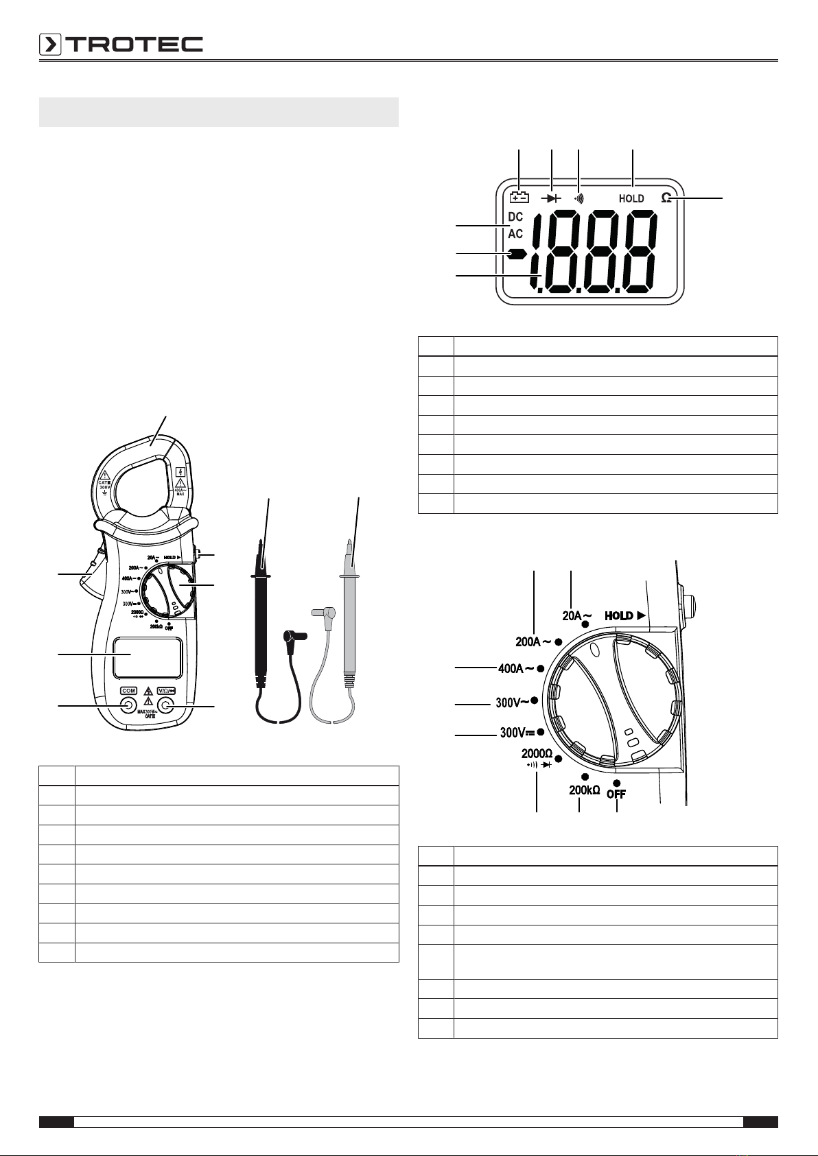
Information about the device................................................3
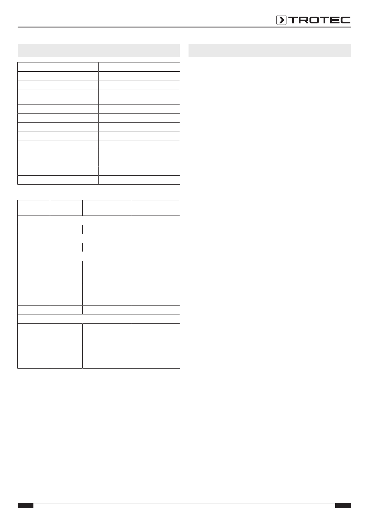
Technical data .......................................................................4
Transport and storage...........................................................4
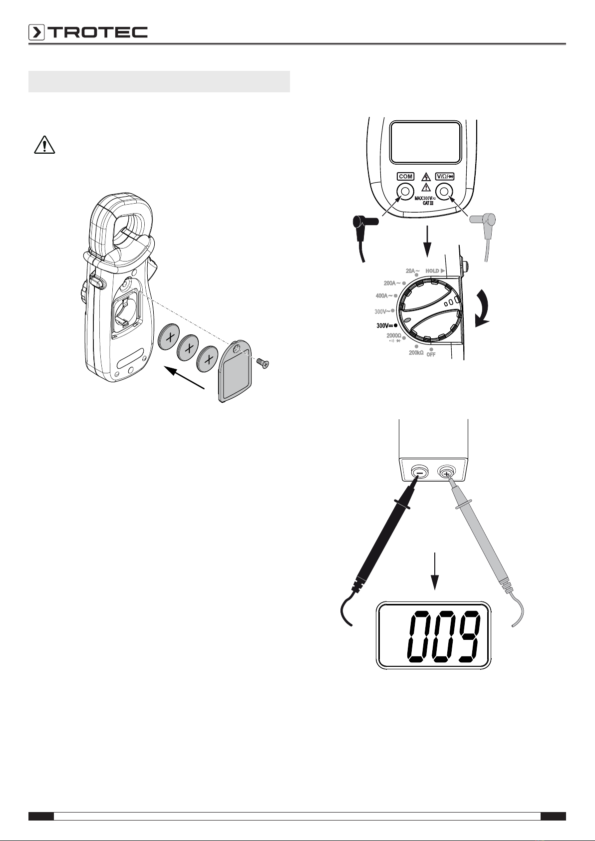
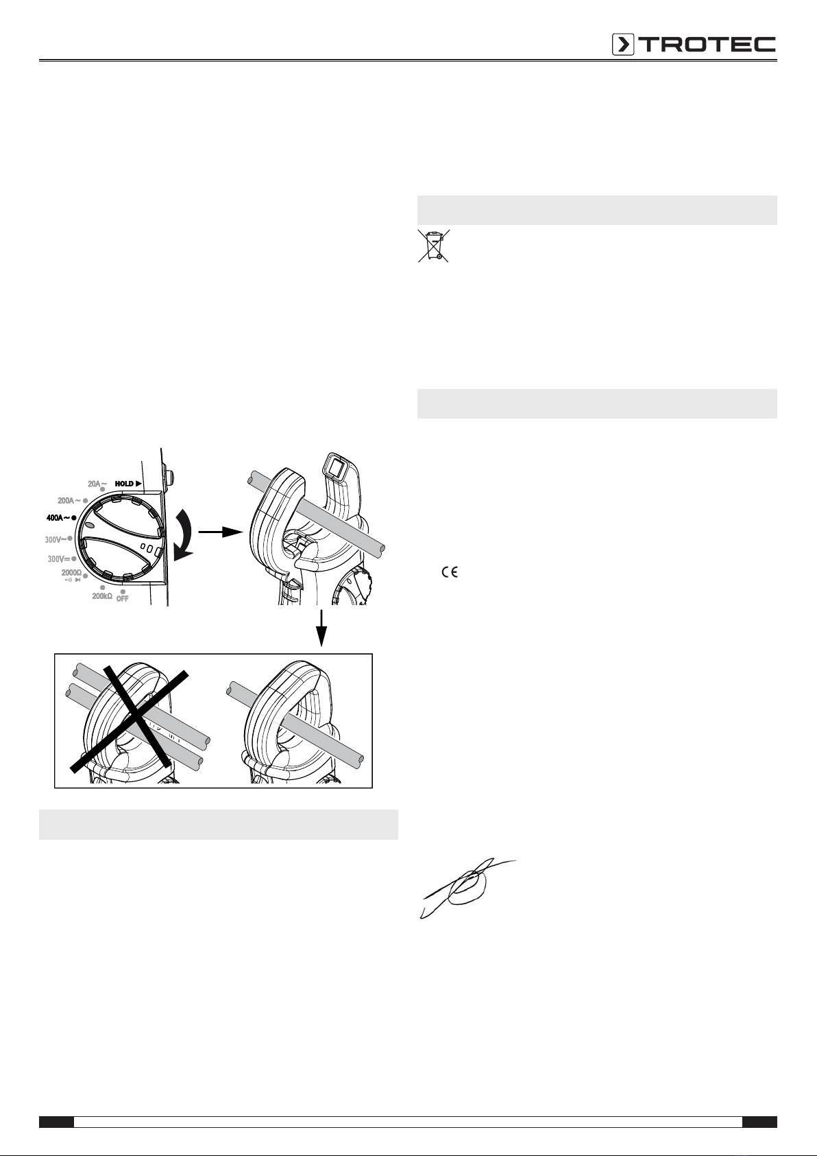
Operation ...............................................................................5
Maintenance and repair ........................................................6
Disposal .................................................................................6
Declaration of conformity .....................................................6
Notes regarding the operating manual
Symbols
Danger from electric current
Warns about hazards from electric current which can
lead to injuries or even death.
Danger
Warns of a hazard which can lead to personal injury.
Caution
Warns of a hazard which can lead to property damage.
The current version of the operating manual can be found at:
BE38
http://download.trotec.com/?sku=3510205239&id=1
Legal notice
This release replaces all previous versions. No part of this
publication may be reproduced without written permission from
Trotec. The same applies for electronically processing,
duplicating or spreading the publication. Subject to technical
changes. All rights reserved. Trademarks are used without
guarantee that they may be used freely and primarily following
the spelling of the manufacturer. Product names are registered.
Changes to construction in the interests of constant
improvements to the product, as well as changes to the shape
and colour are reserved.
The scope of delivery may vary from product images. This
document was created with all due care. Trotec accepts no
liability whatsoever for possible mistakes or omissions.
The only party responsible for determining valid measured
results, drawing conclusions and deriving actions is the user!
Trotec accepts no claims of warranty for the correctness of the
determined measured values or measured results. Further,
Trotec accepts no liability whatsoever for possible mistakes or
damage which have been caused by utilising the determined
measured results.
© Trotec
Warranty and liability
The device complies with the fundamental health and safety
requirements of the applicable EU regulations and was tested at
the factory for perfect functionality multiple times.
If malfunctions occur nonetheless, please contact your dealer or
distributor.
When manufacturer's instructions or legal regulations have not
been followed, or after unauthorised changes to the device are
made, the manufacturer is not responsible for the resulting
damages. Changes to the device or unauthorised replacement
of individual parts can drastically impact the electrical safety of
this product and leads to the forfeit of the warranty. Liability
does not extend to damages to people or property caused by the
device being used other than as described in the instructions in
this operating manual. Subject to changes to technical design
and model changes as part of constant development and
product improvement without prior notice.
No liability is accepted for damages resulting from improper
use. In such a case, any warranty claims be voided also.

EN 2
Operating manual – clamp meter BE 38
Safety
Read this manual carefully before starting or using the
device. Always store the manual in the immediate vicinity
of the device or its site of use!
• Do not use the device in potentially explosive rooms.
• Do not use the device in aggressive atmosphere.
• Protect the device from permanent direct sunlight.
• Do not remove any safety signs, stickers or labels from the
device. Keep all safety signs, stickers and labels in legible
condition.
• Do not open the device with a tool.
• Observe the storage and operating conditions (see chapter
Technical data).
Intended use
This device is intended for measurements in the measuring
range specified in the technical data.
Improper use
Do not use the device in potentially explosive atmospheres,
when wet or very humid.
Unauthorized modifications of the device are forbidden.
Personnel qualifications
People who use this device must:
• have read and understood the operating manual, especially
the Safety chapter.
Residual risks
Danger
Electric shock from contact with live parts. Do not
touch any live parts. Secure neighbouring live parts by
insulating them or switching them off.
Danger
Electric shock from insufficient insulation. Check the
device for damages and proper functioning before each
use.
If you notice damages, no longer use the device.
Do not use the device when the device or your hands
are damp or wet!
Do not use the device when the battery compartment
or the housing are open.
Danger from electric current
Work on the electrical components must only be
carried out by an authorised specialist company!
Danger
Dangers can occur at the device when it is used by
untrained people in an unprofessional or improper way!
Observe the personnel qualifications!
Danger
Do not leave the packaging lying around. Children may
use it as a dangerous toy.
Danger
The device is not a toy and does not belong in the
hands of children.
Caution
To prevent damages to the device, do not expose it to
extreme temperatures, extreme humidity or moisture.
Caution
Do not use abrasive cleaners or solvents to clean the
device.

3 EN
Operating manual – clamp meter BE 38
Information about the device
Device description
Using the clamp meter BE38 alternating current, AC voltage, DC
voltage, resistances or the continuity of circuits, fuses and
contacts can be checked.
The current measurement is effected without contact via the
electromagnetic field, which is why the electric circuit doesn't
have to be interrupted for this method. Therefore, running
systems, which cannot be switched off separately, can also be
checked.
Owing to the galvanic isolation, the measuring signal is also
potential-free towards the variable to be measured.
Device depiction
Ⅲ
1
2
5
6
8
9
3
7
4
No. Designation
1 Clamp
2 Measuring cable (black)
3 Measuring cable (red)
4 Freeze display
5 Rotary switch
6 Connection for measuring cable (red)
7 Connection for measuring cable (black)
8 Display
9 Lever for opening the clamp
Display
13
14
15
17
121110
16
No. Designation
10 Battery indication
11 Diode measurement indication
12 Continuity measurement indication
13 Display is frozen
14 Resistance measurement indication
15 Measurement value display
16 Display of positive and negative poles inverted
17 Direct or alternating current display
Rotary switch
18 19
202122
23
24
25
No. Designation
18 Measuring alternating current of up to 200 A
19 Measuring alternating current of up to 20 A
20 Switching the device off
21 Measuring resistance of up to 200kΩ
22 Measuring resistance of up to 2000Ω / diode testing / continuity
testing
23 Measuring DC voltage of up to bis 300V
24 Measuring AC voltage of up to bis 300V
25 Measuring alternating current of up to 400 A

EN 4
Operating manual – clamp meter BE 38
Technical data
Parameter Value
Model BE38
Weight 127 g (incl. batteries)
Dimensions
(height x width x depth in mm)
148 x 27 x 60
Max. diameter of conductor Approx. 25 mm
Measuring rate 3 per second
Input resistance (VAC and VDC) 9MΩ
Frequency range alternating current 50/60 Hz (AAC)
Frequency range AC voltage 40 - 400 Hz (VAC)
Surrounding conditions 0 °C to 40 °C with up to 75%RH
Storage conditions -20 °C to 60 °C with up to 85%RH
Battery 3x 3V CR2032 button cell batteries
Overvoltage protection Category lll 300 V
Measuring ranges
Measuring
range
Resolution Accuracy Measuring range
exceeded
AC voltage
300 V 1 V ± (1.2 % + 3 digits) - (*)
DC voltage
300 V 1 V ± (1.0 % + 2 digits) - (*)
Alternating current
20 A 10 mA ± (3.0 % + 5 digits) The figure1 will be
indicated on the
display.
200 A 100 mA ± (2.5 % + 5 digits) The figure1 will be
indicated on the
display.
400 A 1 A ± (2.5 % + 5 digits) - (*)
Resistance
2000 Ω 1 Ω ± (1.2 % + 2 digits) The figure1 will be
indicated on the
display.
200 kΩ 100 Ω ± (1.5 % + 2 digits) The figure1 will be
indicated on the
display.
(*): When exceeding the measuring range, the measured value
might be displayed nonetheless.
Please observe the measuring range and the overvoltage
protection! Measurements above the given measuring range are
not permitted!
Scope of delivery
• 1 x Clamp meter BE38
• 3 x button cells 3V CR2032
• 1 x Getting started guide
Transport and storage
Transport
For transporting the device use a suitable bag to protect it from
external influences.
Storage
When the device is not being used, observe the following
storage conditions:
• Dry.
• Protected from dust and direct sunlight.
• With a cover to protect it from invasive dust, if necessary.
• Remove the batteries from the device.

5 EN
Operating manual – clamp meter BE 38
Operation
Inserting the batteries
• Insert the supplied batteries before first use.
Caution
Make sure that the surface of the device is dry and the
device is switched off.
1. Loosen the screw and open the cover of the battery
compartment.
2. Remove the used batteries, if any, and dispose of them
according to the national regulations.
3. Insert the new batteries in the battery compartment with
correct polarity.
4. Close the battery compartment and fasten the cover in
place.
Note:
Note that moving from a cold area to a warm area can lead to
condensation forming on the device's circuit board. This
physical and unavoidable effect can falsify the measurement. In
this case, the display shows either no measured values or they
are incorrect. Wait a few minutes until the device has become
adjusted to the changed conditions before carrying out a
measurement.
Measurement with cable
Example: battery measurement

EN 6
Operating manual – clamp meter BE 38
Resistance measurement
1. Set the rotary switch to position 2000Ω or 200kΩ.
2. Hold the measuring tips to the object to be tested.
ðThe measuring result will be indicated in the
measurement value display.
Continuity measurement / diode test
1. Set the rotary switch to the 2000Ω position.
2. Connect the measuring tips to the diode or the circuit to be
tested.
ðIf during the continuity measurement the resistance is
less than or equal to 30Ω, an acoustic signal will be
emitted.
ðFor the diode test the voltage will be indicated on the
measurement value display in mV.
Measurement with clamp
Maintenance and repair
Cleaning
Clean the device with a soft, damp and lint-free cloth. Ensure
that no moisture enters the housing. Do not use any sprays,
solvents, alcohol-based cleaning agents or abrasive cleaners,
but only clean water to moisten the cloth.
Repair
Do not modify the device or install any spare parts. For repairs
or device testing, contact the manufacturer.
Battery change
A battery change is required when the battery status indication
flashes or the device can no longer be switched on (see chapter
Inserting the batteries).
Disposal
In the European Union, electronic equipment must not be
treated as domestic waste, but must be disposed of
professionally in accordance with Directive 2002/96/EC of the
European Parliament and of the Council of 27January 2003 on
waste electrical and electronic equipment (WEEE). At the end of
its life, please dispose of this device according to the valid legal
requirements.
Declaration of conformity
in accordance with the EC Low Voltage Directive 2006/95/EC
and the EC Directive 2004/108/EC about electromagnetic
compatibility.
Herewith, we declare that the device BE38 was developed,
constructed and produced in compliance with the named EC
directives.
The marking is found on the rear of the device.
Manufacturer:
Trotec GmbH & Co. KG
Grebbener Straße 7
D-52525 Heinsberg
Phone: +49 2452 962-400
Fax: +49 2452 962-200
E-mail: [email protected]
Heinsberg, 01.09.2015
Detlef von der Lieck
Managing Director

Trotec GmbH & Co. KG
Grebbener Str. 7
D-52525 Heinsberg
+49 2452 962-400
+49 2452 962-200
www.trotec.com
Other manuals for BE 38
3
Table of contents
Other Trotec Measuring Instrument manuals

Trotec
Trotec BZ05 User manual

Trotec
Trotec SpeedMarker 700 CL User manual

Trotec
Trotec BM12 User manual

Trotec
Trotec BS30WP User manual

Trotec
Trotec BF06 User manual

Trotec
Trotec BE20 User manual

Trotec
Trotec BA16WP User manual

Trotec
Trotec LD20HC User manual

Trotec
Trotec VSC206 User manual

Trotec
Trotec BB30 User manual
Popular Measuring Instrument manuals by other brands

NEO TOOLS
NEO TOOLS 75-106 user manual

Endress+Hauser
Endress+Hauser Proline Prosonic Flow 91 operating instructions

Olympus
Olympus USPM-RUIII Series Hardware operation manual

Smart Impulse
Smart Impulse SMART X instruction manual

Radiodetection
Radiodetection RD8100 user guide

ANDalyze
ANDalyze AND1100 user manual