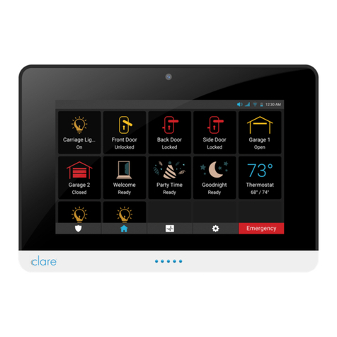
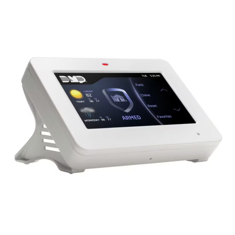
clare ClareOne CLR-C1-PNL1 User manual

ClareOne Wireless Security and
Smart Home Panel User Manual
Model CLR-C1-PNL1
Last modified: 02/20/20
DOC ID - 1871 • Rev 01

Copyright
© 20FEB20 Clare Controls, LLC. All rights reserved.
This document may not be copied in whole or in part or otherwise
reproduced without prior written consent from Clare Controls, LLC.,
except where specifically permitted under US and international
copyright law.
Trademarks and
patents
The ClareOne name and logo are trademarks of Clare Controls,
LLC.
Other trade names used in this document may be trademarks or
registered trademarks of the manufacturers or vendors of the
respective products.
Manufacturer
Clare Controls, LLC.
7519 Pennsylvania Ave., Suite 104, Sarasota, FL 34243, USA
FCC compliance
FCC ID: 2AC9I-C1-PNL1
Contains FCC IDs: XMR201609EC21V and 2AATL-8223A-SR
This device complies with Part 15 of the FCC Rules. Operation is
subject to the following two conditions: (1) this device may not cause
harmful interference, and (2) this device must accept any
interference received, including interference that may cause
undesired operation.
Note: This equipment has been tested and found to comply with the
limits for a Class B digital device, pursuant to Part 15 of the FCC
Rules. These limits are designed to provide reasonable protection
against harmful interference in a residential installation. This
equipment generates, uses and can radiate radio frequency energy
and, if not installed and used in accordance with the instructions,
may cause harmful interference to radio communications. However,
there is no guarantee that interference will not occur in a particular
installation.
If this equipment does cause harmful interference to radio or
television reception, which can be determined by turning the
equipment off and on, the user is encouraged to try to correct the
interference by one or more of the following measures:
-- Reorient or relocate the receiving antenna.
-- Increase the separation between the equipment and receiver.
-- Connect the equipment into an outlet on a circuit different from that
to which the receiver is connected.
-- Consult the dealer or an experienced radio/TV technician for help.
Warning: changes or modifications not expressly approved by the
party responsible for compliance could void the user’s authority to
operate the equipment.
This equipment complies with FCC radiation exposure limits set forth
for an uncontrolled environment. This transmitter must no be co-
located or operating in conjunction with any other antenna or
transmitter.

EU compliance
EU directives
1999/5/EC (R&TTE directive): Hereby, Clare Controls, Llc. declares
that this device is in compliance with the essential requirements and
other relevant provisions of Directive 1999/5/EC.
2004/108/EC (EMC directive): Hereby, Clare Controls, Llc. Declares
that this device is in compliance with the essential requirements and
other relevant provisions of Directive 2004/108/EC.
2006/95/EC (Low Voltage directive): Hereby, Clare Controls, Llc.
Declares that this device is in compliance with the essential
requirements and other relevant provisions of Directive 2006/95/EC.
2002/96/EC (WEEE directive): Products marked with this symbol
cannot be disposed of as unsorted municipal waste in the European
Union. For proper recycling, return this product to your local supplier
upon the purchase of equivalent new equipment, or dispose of it at
designated collection points. For more information see:
www.recyclethis.info.
2006/66/EC (battery directive): This product contains a battery that
cannot be disposed of as unsorted municipal waste in the European
Union. See the product documentation for specific battery
information. The battery is marked with this symbol, which may
include lettering to indicate cadmium (Cd), lead (Pb), or mercury
(Hg). For proper recycling, return the battery to your supplier or to a
designated collection point. For more information see:
www.recyclethis.info.
Contact information
For contact information, see www.clarecontrols.com.


ClareOne i
Content
Important information...iii
Limitation of liability...iii
Introduction...1
Packages contents...1
Specifications...2
Installing the panel...4
ClareOne setup wizard...15
ClareOne Panel menus...18
ClareOne menu bar...18
ClareOne status bar...19
ClareOne quick settings menu...20
Security...22
Security user management...22
Operating security...22
Favorites...28
Activity...31
Settings...32
Display...32
User Settings...33
Installer Settings...34
About...34
User and Installer Settings...35
User Management...36
WiFi...42
Time Zone...43
Security & Arming...44
Sensor Management...46
Restart...52
System Test...52
Check for Updates...56
Panel Reset...58
Demo Mode...59

ii ClareOne
Emergency...61
Basic operation...65
Panel states...65
Panel LED...65
Maintenance...66
Contact...67
Evacuation plan...68
Glossary...71
Appendices...72
Quick reference...73
Trouble conditions...76
Panel zone list tracking...77
Sensor installations and specifications...79
ClareOne Keyfob Installation Sheet...80
ClareOne Door/Window Sensor Installation Sheet...84
ClareOne PIR Motion Sensor Installation Sheet...92
ClareOne Panic Pendant Installation Sheet...102

ClareOne iii
Important information
Limitation of liability
To the maximum extent permitted by applicable law, in no event will Clare
Controls, LLC. be liable for any lost profits or business opportunities, loss of use,
business interruption, loss of data, or any other indirect, special, incidental, or
consequential damages under any theory of liability, whether based in contract,
tort, negligence, product liability, or otherwise. Because some jurisdictions do not
allow the exclusion or limitation of liability for consequential or incidental
damages the preceding limitation may not apply to you. In any event the total
liability of Clare Controls, LLC. shall not exceed the purchase price of the
product. The foregoing limitation will apply to the maximum extent permitted by
applicable law, regardless of whether Clare Controls, LLC. has been advised of
the possibility of such damages and regardless of whether any remedy fails of its
essential purpose.
Installation in accordance with this manual, applicable codes, and the instructions
of the authority having jurisdiction is mandatory.
While every precaution has been taken during the preparation of this manual to
ensure the accuracy of its contents, Clare Controls, LLC. assumes no
responsibility for errors or omissions.


ClareOne 1
Introduction
The ClareOne Wireless Security and Smart Home Panel (CLR-C1-PNL1) is a
smart home hub featuring customizable home automation and security control.
The ClareOne eliminates the need for separate control and customization
devices.
Package contents
Note: Ensure all accessories are included. If not, contact the dealer.
•1 x ClareOne panel (CLR-C1-PNL1)
•1 x Battery (CLR-C1-BATT, located inside battery compartment of the panel)
•1 x Wall mount bracket and Kickstand (CLR-C1-STND)
•1 x Power supply (CLR-C1-12VA)
•1 x USB-C Ethernet adapter (CLR-C1-ETH)
•1 x ClareOne Quick Start Guide (DOC ID 1885)
•Mounting hardware (screws and wall anchors)
•1 x ClareOne bezel –white (CLR-C1-BZL-W)
•1 x ClareOne bezel –black (CLR-C1-BZL-B, attached to panel)
Optional kits may include:
•ClareOne Door/Window Sensor, white (CLR-C1-DW-W)
•ClareOne Keyfob (CLR-C1-KF)
•ClareOne PIR Motion Sensor (CLR-C1-PIR)
Additional accessories available include:
•ClareOne Door/Window Sensor, brown (CLR-C1-DW-B)
•ClareOne CO Sensor (CLR-C1-CO)
•ClareOne Smoke Sensor (CLR-C1-SMK)
•ClareOne Panic Pendant (CLR-C1-PNC)
•ClareOne Water Sensor (CLR-C1-WTR)
•ClareOne Rate of Rise Heat Detector (CLR-C1-HT)
•ClareOne Glass Break Detector (CLR-C1-GB)
•ClareOne Z-Wave Siren (CLR-C1-ZW-SRN)

2 ClareOne
Specifications
Touchscreen
Size
7 in (18 cm)
Resolution
1024 × 600
User Interface
Status LED
Multi-color
Voice announcement
System state, sensor state, disarm state
User codes
Up to 99 users and 10,000 possible codes
Proximity sensor
5 ft (1.52 m) auto-wake up motion detection
Radio/Network
WiFi
WiFi 802.11 a/b/g/n/ac dual band 2.4/5G
Ethernet/LAN
USB-C to ethernet adapter
Z-Wave
Z-Wave Plus
Cellular
Verizon LTE with two-way voice
Security R/F
Encrypted, two-way, 433MHz, 1 partition, 128 sensor zones
Siren and Audio
Internal
Piezo, above 87db at 10 ft (3.04 m)
Contact closure port
1
Wireless
Z-Wave
Audio detection
T3 and T4 alarm detection (smoke and CO)
Power/Battery
DC Power
12VDC 2500mA, Input 100-240VAC 50/60Hz
Connector
Micro USB or screw terminals
Power consumption
30W maximum
Battery type
Rechargeable lithium-ion battery, 5200mAh
Maximum battery voltage
4.35V
Battery duration
24 hours + 4 minutes of continued alarm after the 24-hour period
Changeable battery
Yes, user can change
Mechanical
Tamper switch
Panel tamper switch with spring release and status reporting
Operational temperature
32 to 120° F (0 to 48.8° C)
Humidity
85 ± 5% at 86 ± 3°F for 24 hours
Mount
Includes wall and two position tabletop stand
Panel dimensions
(W × H × D)
7.7 × 5.3 × .8 in. (194.8 × 134.9 × 20.6 mm)

ClareOne 3
Figure 1: ClareOne Panel - front
(1) Camera
(2) IR sensors (2 on each side)
(3) Microphones (on each side)
(4) LED
Figure 2: ClareOne Panel - exterior rear
(1) Tamper button
(2) Back plate secure screw
(3) Rear panel cover
(4) Mounting holes
(5) Siren
(6) DC routing hole #1
(7) DC routing hole #2
(8) LAN routing hole
(9) Siren routing hole

4 ClareOne
Figure 3: ClareOne Panel - interior rear
(1) DC wiring terminal
(2) DC micro USB port
(3) LAN port (USB-C)
(4) Panel reset hole
(5) SIM card slot
(6) Battery connection
(7) Battery
(8) Siren wiring terminal
Installing the panel
Only qualified installation technicians should install the panel. Clare Controls
does not assume responsibility for damages caused by improper installation,
connection to the network, or use of the device.
Installation options
The ClareOne panel can be installed using a desktop stand or a wall mount.
Power options
The panel can be powered by the provided power supply with a micro USB
cable, using the provided power supply with Cat5/6 cable, or using the provided
power supply with 22AWG or thicker shielded security wiring. For details on the
ClareOne panel power options, see Power supply options on page 9.
Note: In the case of a power outage, the battery in the panel lasts 24 hours plus
an additional 4 minutes of alarm signaling.

ClareOne 5
Installation option 1: Desktop
Option 1 uses the included kickstand.
To desktop mount the panel:
1. Remove the panel’s back plate by pressing down on the 2 tabs and pulling
the back plate outward, exposing the battery.
2. Route the power supply cable through the hole in the bottom right side of the
kickstand.
3. Verify that the battery is plugged in, and then attach the power supply to the
panel.
Note: For other power options, see Power supply options on 9.

6 ClareOne
4. Attach the panel’s back cover, gently pressing it into place. Verify that the
tabs are both fully pressed in.
5. Press the sides of the back plate against the back of the panel, making sure
there is no gap between the back plate and the panel.
6. Align the mounting holes in the back of the panel with the stubs on the
kickstand, and then press kickstand to the rear of the panel.
7. Slide the panel down, locking it into place.
8. Plug the opposite end of the power supply into an electrical outlet.
The panel automatically powers up.
Note: Do not connect to a receptacle controlled by a switch.
9. (Optional) The viewing angle of the panel can be adjusted by pressing the
kickstand tab and sliding the base up or down to the desired position, locking
it into place.

ClareOne 7
Installation option 2: Wall mounted
Option 2 uses the included wall mount bracket. The recommended height for
mounting the panel is 48 in. +/- 12 in. based on the comfort level of the end user.
To wall mount the panel:
1. Select a location for the panel that is close to an outlet, and then run a
connection from the 12VDC supply to the selected installation location.
2. Place the mounting bracket against the selected wall location or gang box,
ensuring that the power cable goes through the center of the mounting
bracket.
Note: The cable does not need to go through the mounting bracket if the
power cable does not run through the wall.
3. Using included screws securely attach the bracket to the gang box or wall.
See the methods below.
a. Gang box: Using 2 of the included machine screws, secure the
bracket to the existing gang box.
b. Mounting hole: Mark the locations of the 4 holes in the wall mount
bracket on the wall, be sure to keep the bracket level when marking
the locations. Using a power drill with 5 mm bit, drill a hole at each
location. Insert one of the included wall anchors into each of the 4
holes. Match the wall mount bracket to the anchor locations. Secure
the panel to the wall using the provided screws in the 4 holes.
4. Remove the panel’s back plate by pressing down on the 2 tabs and pulling
the back plate outward.

8 ClareOne
5. Verify that the battery is plugged in, and then attach the power supply to the
panel.
6. Attach the panel’s back cover, gently pressing it into place.
7. Press the sides of the back plate against the back of the panel, making sure
there is no gap between the back plate and the panel.
8. Press the panel onto the mounting bracket, and then slide the panel down
until it locks into place.
9. Plug the opposite end of the power supply into an electrical outlet.
The panel automatically powers up.
Note: Do not connect to a receptacle controlled by a switch.

ClareOne 9
Power supply options
The ClareOne Panel has 2 power options: localized (using provided power
supply with micro USB within 6 ft of the installation location) and remote (using
CAT5/6 or 22AWG or thicker shielded security wire to extend the reach up to
100 ft from the installation location).
Localized power
The power supply provided with panel come with a 6 ft micro USB cable
attached.
Note: Only use the provided 12VDC power supply. Do not use any other power
supply with the panel.
To use localized power:
1. Remove the panel’s back plate by pressing down on the 2 tabs and pulling
the back plate outward.
2. Plug the micro USB cable into the panel’s micro USB DC port. See Figure 3:
ClareOne Panel - interior rear on page 4.
3. Replace the back plate, and then plug the power supply into the closest wall
outlet.
Note: Do not connect to a receptacle controlled by a switch.
Remote power
For installation locations that are further than 6 ft from the nearest outlet, the
power supply cable can be removed and replaced with a CAT5/6 cable or an
22AWG or thicker shielded security wire. This allows the power supply to be
located up to 100 ft away from the panel. For details regarding wire gauges and
distance, see ClareOne Remote Power Tech Bulletin (DOC ID 1937).
Note: When using CAT5/6 cable the single wires must have a minimum gauge of
24AWG. In addition, a twisted pair of the wires must be used to connect to each
of the positive and negative terminals in order to reach 100 ft.
To power a panel more than 6 ft away from an outlet:
1. Remove the panel’s back plate by pressing down on the 2 tabs and pulling
the back plate outward, exposing the rear interior.
2. Carefully insert the positive end of the wire into the positive terminal of the DC
power terminal.

10 ClareOne
3. Carefully insert the negative end of the wire into the negative terminal of the
DC power terminal.
4. Replace the back plate on the panel.
5. Connect the wires to the positive and negative terminals on the power supply.
6. Secure the power supply mounting bracket to the closest wall outlet using the
provided screws, and then plug the power supply into the outlet.
Note: Do not connect to a receptacle controlled by a switch.
7. Use the provided zip tie to loop through the mounting bracket, securing the
power supply.

ClareOne 11
Panel battery specifications and maintenance
The ClareOne Panel uses a rechargeable lithium-ion battery, specs listed below.
Table 1: ClareOne Panel Battery Specifications
Battery type
Rechargeable Lithium-ion battery, 5200mAh
Maximum battery voltage
4.35V DC
Maximum charging current
2600mA
Charging time
6.5 hours (at standard charge rate of 1040mA)
Manufacturer
Guangdong Pow-Tech New Power Co., Ltd.
Manufacturer part number
PT985082-PCM5200
Connector
3 pin latching connector
Battery duration
24 hours + 4 minutes of continued alarm after the
24-hour period
Changeable battery
Yes, user can change
Battery maintenance
The battery is rated to last over 18 years in typical installation environments. For
proper upkeep and panel reliability, the rechargeable battery should be
periodically tested by verifying that the panel operates without AC power. If the
battery needs to be replaced, a replacement battery can be ordered using Clare
Controls part number CLR-C1-BATT. The current battery capacity is displayed by
the battery indicator in the Status Bar (Figure 9).
To replace the battery:
1. Remove the panel’s back plate
2. Press down on the battery cable header tab, and then carefully pull down on
the header, releasing it from the connector on the panel.
3. Remove the battery and dispose of it properly.

12 ClareOne
4. Insert the new battery’s header into the battery port on the panel
5. Gently place the battery into position with the battery’s cabling going above
the battery in the back of the panel.
6. Return the panel’s back plate.
Wired siren
The ClareOne Panel has a 2 pin terminal connector to attach an external wired
siren. The connector is labeled as “SIREN” and uses a 2-screw terminal. The
siren output acts as a simple contact closure, resulting in the wiring polarity being
irrelevant for connection. The wired siren and its power supply should be
connected as shown below. Use Class B wiring for all connections.
For more information on ClareOne Panel wired sirens, see ClareOne Wired
Sirens Integration Notes (DOC ID 1936).
Other manuals for ClareOne CLR-C1-PNL1
4
Table of contents
Other clare Control Panel manuals
