manuals.online logo
Brands
  1. Home
  2. •
  3. Brands
  4. •
  5. Clarion
  6. •
  7. Car Video System
  8. •
  9. Clarion CC4100E User manual

Clarion CC4100E User manual

Other Clarion Car Video System manuals

Clarion OHM733 User manual

Clarion

Clarion OHM733 User manual

Clarion PN-2940S-A User manual

Clarion

Clarion PN-2940S-A User manual

Clarion NX602 User manual

Clarion

Clarion NX602 User manual

Clarion NX404E User manual

Clarion

Clarion NX404E User manual

Clarion VT1010E Manual

Clarion

Clarion VT1010E Manual

Clarion VT101OE Repair manual

Clarion

Clarion VT101OE Repair manual

Clarion VX316A User manual

Clarion

Clarion VX316A User manual

Clarion NX405 User manual

Clarion

Clarion NX405 User manual

Clarion VX404E User manual

Clarion

Clarion VX404E User manual

Clarion VT800B User manual

Clarion

Clarion VT800B User manual

Clarion VMA7191 User manual

Clarion

Clarion VMA7191 User manual

Clarion NX316AU User manual

Clarion

Clarion NX316AU User manual

Clarion NX807E User manual

Clarion

Clarion NX807E User manual

Clarion NX403EV User manual

Clarion

Clarion NX403EV User manual

Clarion OHM102/OHM153 Service manual

Clarion

Clarion OHM102/OHM153 Service manual

Clarion VRX585USB Repair manual

Clarion

Clarion VRX585USB Repair manual

Clarion NX602 User manual

Clarion

Clarion NX602 User manual

Clarion VRX878RVD Repair manual

Clarion

Clarion VRX878RVD Repair manual

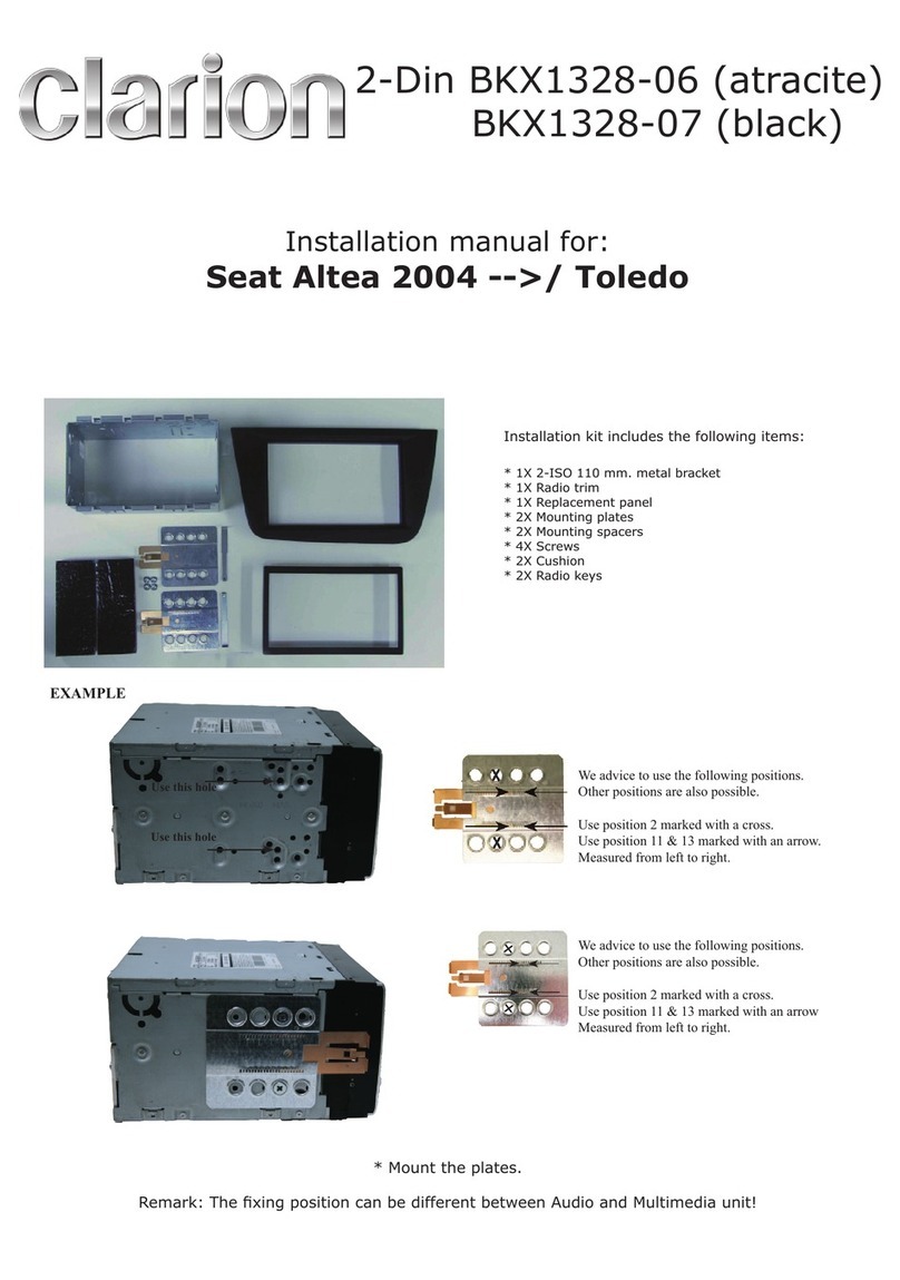
Clarion BKX1328-06 User manual

Clarion

Clarion BKX1328-06 User manual

Clarion VRX868RVD Repair manual

Clarion

Clarion VRX868RVD Repair manual

Clarion BKX-1094-03 User manual

Clarion

Clarion BKX-1094-03 User manual

Clarion NX505E User manual

Clarion

Clarion NX505E User manual

Clarion CC-2012E User manual

Clarion

Clarion CC-2012E User manual

Clarion CJ-981E Repair manual

Clarion

Clarion CJ-981E Repair manual

Popular Car Video System manuals by other brands

Farenheit MD-1510CM instruction manual

Farenheit

Farenheit MD-1510CM instruction manual

Mazda Connect manual

Mazda

Mazda Connect manual

RCA DRC97983 Manual de usuario

RCA

RCA DRC97983 Manual de usuario

Panasonic CY-VHD9401U Service manual

Panasonic

Panasonic CY-VHD9401U Service manual

Stinger HEIGH10 RB10RAM13B installation manual

Stinger

Stinger HEIGH10 RB10RAM13B installation manual

Alpine IVA-W203 - 6.5" Touch Screen 2-DIN DVD In-Dash... owner's manual

Alpine

Alpine IVA-W203 - 6.5" Touch Screen 2-DIN DVD In-Dash... owner's manual

Eonon E1057 instructions

Eonon

Eonon E1057 instructions

Milion D2223 user manual

Milion

Milion D2223 user manual

Metra Electronics 99-8153 installation instructions

Metra Electronics

Metra Electronics 99-8153 installation instructions

Voxx Electronics HR8MA1 owner's manual

Voxx Electronics

Voxx Electronics HR8MA1 owner's manual

Axxera AV604Bi quick start guide

Axxera

Axxera AV604Bi quick start guide

Pyle view PLDN74BTi owner's manual

Pyle view

Pyle view PLDN74BTi owner's manual

RCA DRC6296 - Twin 9" Mobile DVD System Manual Del Usuario

RCA

RCA DRC6296 - Twin 9" Mobile DVD System Manual Del Usuario

Fiat Uconnect 5.0 manual

Fiat

Fiat Uconnect 5.0 manual

Lanzar SVDVD5 owner's manual

Lanzar

Lanzar SVDVD5 owner's manual

Eonon E1060 instructions

Eonon

Eonon E1060 instructions

Macrom M-AN900 user manual

Macrom

Macrom M-AN900 user manual

Hyundai BAPE-L3000N user manual

Hyundai

Hyundai BAPE-L3000N user manual

manuals.online logo
manuals.online logoBrands
  • About & Mission
  • Contact us
  • Privacy Policy
  • Terms and Conditions

Copyright 2025 Manuals.Online. All Rights Reserved.

CC4100E
ULTRA COMPACT COLOR CAMERA with Heavy Duty
Mounting Bracket and Metal Shroud
Installation manual
Printed in China 20011/6 274-0383-00
1. FEATURES
■High-performance 1/4" color CMOS sensor
■130° (horizontal) wide-angle lens, allowing broad field of view
■Mirror-image inversion function presents optimum conditions for confirming rear view
(same right-left orientation as seen through a rear-view mirror)
■Small size and weight for easy installation
2. PRECAUTIONS
This equipment has been tested and found to comply with the limits for a Class B digital device, pursuant
to Part 15 of the FCC Rules.
These limits are designed to provide reasonable protection against harmful interference in a residential
installation.
This equipment generates, uses, and can radiate radio frequency energy and, if not installed and used
in accordance with the instructions, may cause harmful interference to radio communications. However,
there is no guarantee that interference will not occur in a particular installation.
If this equipment does cause harmful interference to radio or television reception, which can be determined
by turning the equipment off and on, the user is encouraged to consult the dealer or an experienced radio/
TV technician for help.
INFORMATION FOR USERS:
CHANGES OR MODIFICATIONS TO THIS PRODUCT NOT APPROVED BY THE MANUFACTURER
WILL VOID THE WARRANTY AND WILL VIOLATE FCC APPROVAL.
• Thisdevicehasbeendesignedexclusivelyforusewithavehicularmountedrear-viewtelevision
system. It should not be used for other purposes.
• Disconnectthevehicle’snegative(–)terminalwheninstallingwiring.
• Donotattempttodisassembleormodifythisproduct.
• Intheeventitisnecessarytodrillholesinthevehicleformounting,conrmthatthedrillbitor
camera wiring will not strike or interfere with piping, gas tank, electrical wiring or other functional
parts of the vehicle.
• Donotrelysolelyonthemonitorimagewhenreversingthevehicle.
The rear-view monitor is an auxiliary device meant for confirming the presence of obstacles to the
rear of the vehicle, and is limited in its range. It should be used only in conjunction with direct visual
observations.
• Alwaysreverseatlowspeeds.
The rear-view monitor produces a wide-angle image, with the result that actual distances may be
different than they subjectively appear in the monitor.
• Donotusewhentheimagingsurfaceorotherpartsaremalfunctioning.
• Wheninstallationandwiringarecompleted,conrmthatthevehicle’shorn,brakeandwarning
lights, and other electrical equipment function properly as designed.
• InstallonlyasdirectedintheInstallationManual.
• Installaccessorypartsasdirected.
• Whendrillingholesinthevehicleforinstallationofwiring,alwaysuseinsulatedgrommetsinthe
holes to protect the wiring.
• Ifholesaredrilledinthevehicletoinstallthecamera,orwheninstallingwiring,usesilicon
sealant to seal any gaps.
• Donotdamageorscarthecamerawiring.
• Aftercompletingthecamerawiring,usecableclampsorinsulationtapetobundlethewiring
together.
• Theimagesproducedfromtherear-viewmonitorareinvertedright-leftinthesamewayas
imagesseeninthevehicle’srear-viewmirrors.Theimagemaydifferdependingonthevehicle
type.
• Donotusehigh-pressurecarwashingdevicesaroundthecamera.
The camera is a high-precision instrument and should not be subjected to high-pressure water
stream impacts.
• Periodicallycheckthetightnessoftheinstallationscrewsandretightenifnecessary.
WARNING
CAUTION
3.PACKAGECONTENTS
1Camera (with 0.5 m cable) ............................. 1
2Mounting bracket ............................................ 1
3Protective cover.............................................. 1
4Installation screws (hex head M3 x 6) ............ 2
1
2 3
5
87
6
4
5Installation screws (hex head M3 x 15) .......... 2
6Installation screws (pan head M3 x 7) ............ 2
7Flange nuts (M3) ............................................ 2
8Owner’s manual & Installation manual ........... 1
4. INSTALLATION
Before installation
• Beforeinstallingthecameraoritswiring,readallsafetywarningsandbesuretoinstalltheunitcorrectly.
• Beforeinstallingthecamerapermanently,useadhesivetapetomountthecamerainitsproposed
position, then check the image in the monitor to confirm proper display before fixing the camera in its
final position.
• Disconnectthebattery’snegative(–)terminalinstallingwiring.
Installing the camera
1. Attach mounting bracket to vehicle
Using two installation screws (hex head M3 x 15), attach the mounting bracket to the vehicle.
Mounting bracket
Flange nuts (M3)
Installation screws
(hex head M3 x 15)
2. Attach the protective cover to the camera
Use two installation screws (pan head M3 x 7) to attach the protective cover to the camera
body.
Protective cover
Camera
Installation screws (pan head M3 x 7)
3. Attach the camera to the mounting bracket
Using two installation screws (hex head M3 x 6), attach the camera to the mounting bracket
as shown. Adjust the angle of the camera as desired before tightening the screws holding the
protective cover to the mounting bracket.
Mounting bracket
Installation screws
(hex head M3 x 6)
Camera Protective cover
• Whenadjustingthecameraposition,donotallowthecameracabletobeexcessivelystretched
or loose.
• Periodicallycheckthetightnessoftheinstallationscrewsandretightenifnecessary.
■ Adjustingcameraangle(example)
Whenthecameraanglehasbeenchanged,therangedisplayedbytheimageonthemonitorwill
change. Always confirm by direct observation when backing the vehicle.
37.5°
WARNING
CAUTION
CAUTION
Precaution:
• Takecarenottodamagethecamera
bodywheninstallingthecover.
5.WIRING
1Lead the camera cable into the vehicle and align it along the vehicle weather stripping. Fix the wires in
place and prevent them from being pinched in hinges or dampers.
2Using an optional extension cable, the camera cable can be installed under the vehicle floor (carpet) to
connect to a Clarion rear-view monitor.
Exclusive waterproof relay cable (sold separately)
Inside the vehicle
Outside the vehicle
Securely tighten the connectors.
CMOS camera
Monitor for
Clarion rear-view
CCA-532-100 (7 m)
CCA-533-100 (10 m)
CCA-534-100 (15 m)
Use:
When used as part of a Clarion vehicle-mounted rear-view camera system, the rear-
view image is displayed on the monitor when the vehicle’s transmission is placed in
reverse, or when the monitor’s manual switch is used.
■ WaterproofConnectorFasteningProcedureandCautions
1wMark : Align the arrow marks on both connectors in order to connect the cable.
Exclusive waterproof
relay cable (female)
Camera cable (male)
2Hold the two connectors together and twist the ring on the camera cable’s connector as far as it will go.
Twist the ring in the direction
of the arrow while holding both
connectors together.
Twist the yellow ring until there is no gap between the ring and the connector.
Should∫ïhere be any gap between the ring and the connector, twist the ring to close it.

Gap
Note:
• SeetheInstructionManualsuppliedwiththe
monitorforinformationregardingwiring,operation,
andcompositionofthemonitorunit.
CAUTION
7. SPECIFICATIONS
Power source/voltage: DC 9 V (±0.5 V)
Power consumption: 100 mA or less
Image sensor: 1/4" color CMOS
Angle of view: 130° (horizontal)
98.8° (vertical)
Minimum subject illumination: 3 LUX or less
SN ratio: 36 dB or more
Weight: About 80 g (bracket and 0.5 m cable)
Dimensions: 24 (W) ×24 (H) ×22 (D) mm
Note:
• Specicationsanddesignaresubjecttochangewithoutnoticeforfurtherimprovement.
6.TROUBLESHOOTING
Symptom
No image
Poor image is produced
Reason
Wiring is incomplete or disconnected.
A fuse is burned out.
The lens cover is soiled.
Sunlight or headlights from a vehicle
in the rear are shining directly in the
camera.
The environment is too dark.
The level of illumination outside the
vehicle changed too abruptly.
Solution
Check wiring once again and confirm
correct connections.
When using an independent power
supply box, check the fuse and, if
burned out, replace with a new one
of the same capacity (1 A). If the fuse
burns out repeatedly, consult your
dealer or nearest Clarion Service
Center.
Wipe lightly with a damp soft cloth.
Do not rub harshly with dry cloths
since scratches may be produced.
The image will return to normal when
the light striking the lens is removed.
The image display will be poor at
night or in dim light.
The image will return to normal in
conditions of brighter illumination.
When moving from a bright to a
dark location (especially from bright
sunlight to shade), the image may
appear excessively dark.
When moving from a dark to a bright
location (especially from shade into
bright sunlight), the screen image
may appear excessively bright.
This model CC4100E is following the provisions of Directive
2004/108/EC and Directive 2004/104/EC.
Authorized Representative
Clarion Europe S.A.S.
Z.I. du Pré à Varois, Route de Pompey, 54670 Custines, France
telephone: +33 (0)3 83 49 44 00 facsimile: +33 (0)3 83 49 44 21