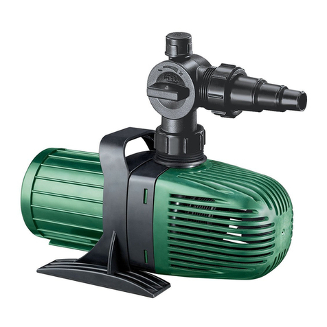
Clarke SSP3 Installation and operation manual

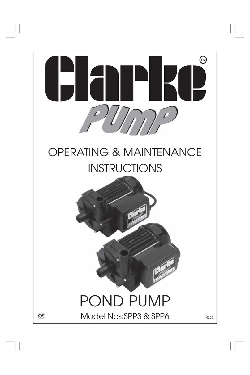
OPERATING & MAINTENANCE
INSTRUCTIONS
POND PUMP
Model Nos:SSP3 & SSP6 0111

Thank you for purchasing this CLARKE Water Pump, which is particularly suitable
for the filtration of small to medium size swimming pools and ponds and for pumping
clean water or water containing small solids in suspension.
To help ensure long, trouble free performance and the protection afforded by
the warranty, please carefully follow all the instructions and recommendations
given in this booklet.
GUARANTEE
This CLARKE product is guaranteed against faulty manufacture for a period of 12
months from the date of purchase. Please keep your receipt as proof of purchase.
This guarantee is invalid if the product is found to have been abused or tampered
with in any way, or not used for the purpose for which it was intended.
Faulty goods should be returned to their place of purchase. No product can be
returned to us without prior permission. This guarantee does not effect your
statutory rights.
SAFETY PRECAUTIONS
1. Ensure the pump is installed in a horizontal position with the outlet facing
vertically upwards, and that it is firmly anchored via its fixing screws.
2. Ensure there is an adequate air flow around the pump. DO NOT mount it in an
enclosed atmosphere.
3. Ensure all water pipes - supply or discharge, are adequately supported where
necessary, so as not to put a strain on the pump connections.
4. DO NOT allow the pump to run dry, as this will cause serious damage to the
pump seals.
5. Ensure the inlet to the pump is completely unrestricted.
6. Ensure the pump is protected from the elements, neither the motor nor the
electrical terminal box is intended to be waterproof.
7. Ensure that all pipes are protected against damage where necessary, and
that they are suitably lagged to avoid the possibility of freezing during cold
weather.
8. NEVER switch the pump ON when the pool is in use. ALWAYS disconnect the
pump from the electrical supply.
9. THIS PUMP MUST BE CONNECTED TO THE ELECTRICAL SUPPLY VIA A
RESIDUAL CURRENT DEVICE (RCD)
2

3
ELECTRICAL CONNECTIONS
WARNING!
THIS PUMP MUST BE CONNECTED TO THE ELECTRICAL SUPPLY
VIA A RESIDUAL CURRENT DEVICE (RCD)
Connect the mains lead to a standard, 230 Volt (50Hz) electrical supply through
an approved 13 amp BS 1363 plug via an Residual Current Device.
WARNING! THIS APPLIANCE MUST BE EARTHED
IMPORTANT: The wires in the mains lead are coloured in accordance with the
following code:
Green & Yellow - Earth
Blue - Neutral
Brown - Live
As the colours of the flexible lead of this appliance may not correspond with the
coloured markings identifying terminals in your plug proceed as follows:
• Connect the GREEN & YELLOW cord to terminal marked with a letter
“E” or Earth symbol “ ” or coloured GREEN or GREEN & YELLOW.
• Connect BROWN cord to terminal marked with “L” or coloured RED.
• Connect BLUE cord to the terminal marked with “N” or coloured BLACK.
If this appliance is fitted with a plug which is moulded onto the electric cable (i.e.
non-rewirable) please note:
1. The plug must be thrown away if it is cut from the electric cable. There
is a danger of electric shock if it is subsequently inserted into a socket outlet.
2. Never use the plug without the fuse cover fitted.
3. Should you wish to replace a detachable fuse carrier, available from your
local dealer or most electrical stockists, ensure that the correct replacement
is used (as indicated by marking or colour code).
Fuse Rating
The fuse in the plug must be replaced with one of the same rating - 13amps and
this replacement must be ASTA approved to BS1362.
Cable Extension
If a cable extension is needed, it is essential to ensure that the size of the
conductors is at least the same size as those of the power cable supplied.
Do not attempt electrical installation work if you are in any doubt as
to how it should be done properly. Consult a qualified electrician.

4
WATER CONNECTIONS
IMPORTANT: DO NOT connect the pump to the power supply until the hose/pipe
installation is completed.
Because of the variety of possible installations, no plumbing accessories are
supplied as standard with your pump. However, accessories designed specifically
for this range of pumps are available from your CLARKE dealer and are listed on
page 6.
from an above ground pool. However, it is possible
to draw water from a sunken pool, providing the
suction lift does not exceed the distance specified
for your pump (see Specifications on page 7).
A. SUCTION LIFT
The suction lift i.e. the vertical distance between
the water level and the pump should not exceed
the distance specified for your pump (see
Specifications on page 7).
A foot valve/filter MUST be fitted to the lower end
of the suction hose, (as illustrated in fig.2), so as to
help retain water in the suction system.
Remember.... this is NOT a self priming pump.
The pump must always be installed and
operated in a horizontal position i.e. with the
outlet port (see Fig.1), facing vertically
upwards. The fixing slots in the base should
be used as necessary to secure the pump
firmly in its operating position. Also, ensure
that there is adequate air circulation around
the motor.
Avoid situations where there is the risk of
water coming into contact with the outside
of the pump. Neither the motor or the
terminal box are intended to be waterproof.
Attach suitable 1” ID hose to the inlet port, securing with a worm drive clip. The
other end of the hose should be connected to a strainer, or foot valve/filter
depending upon the type of installation (see below), and should rest on the bottom
of the pool. Ensure all connections are air tight.
Attach also a suitable 1” ID hose to the outlet port using a worm drive clip. The
other end of the hose should be connected to your Water Filter (available from
your Clarke dealer - see page 6). Ensure there are no kinks in the hose.
These notes are for guidance on how to achieve a proper working system.
The schematic diagrams, figs. 3 and 4, illustrate possible methods of pipework
installation. This pump is designed primarily, to br gravity fed, that is, drawing water
Fig.1
Foot Valve/
Filter
Fig.2
5
The delivery head i.e. the vertical
distance between the pump and
the point of discharge should not
exceed distance specified for your
pump (see Specifications, page
7).
When suction lift is used to draw
water into the pump it is essential
that all connections and hoses are
1. With the pump, all inlet pipes/hoses and the foot valve in position, slowly pour
water into the outlet port. Wait until all air is expelled...this may take a minute
or two...and fill to the brim before connecting the outlet hose to the outlet
port. The hose is then led away to the water filter.
2. Switch on the pump. Water should start to flow through the system.
Check for leaks and repair as necessary
Do not allow the pump to run dry, otherwise the seal between the pump and motor
may be damaged. If a leak is noticed at this point it may indicate that the seal is
worn and therefore in need of replacement. Contact your CLARKE dealer, or the
Clarke International Service Department for advice.
B GRAVITY FEED
Do not place any restriction on the
inlet side of the pump.
The delivery head i.e. the vertical
distance between the pump outlet
and the point of discharge should
not exceed distance specified for
your pump (see Specifications, page 7).
To prevent unnecessary strain or possible distortion to the pump, ensure that
adequate support is provided to the hoses and/or pipes. Remember they will be
considerably heavier when filled with water.
Remember - this pump is designed for pumping CLEAN WATER with small solids in
suspension, ONLY. DO NOT USE for pumping chemicals or other corrosive liquids
(other than pool purification chemicals in their correct mix ratio).
Protect the pump and pipework from freezing. The formation of ice may cause
serious damage.
NOTE: For the fitting of filters/strainers, please consult the manufacturers manual.
completely air tight, otherwise the system will
not work.
Before pumping will start it is essential to
completely fill the suction side with water. This
is known as priming the pump and is carried
out as follows :-
Fig.4
Fig.3

6
TROUBLE SHOOTING
If the system is set up properly, there is little likelihood of problems arising, but if
water will not flow as it should then check the following points:-
1. If using a suction lift, the suction hose and connections need to be completely
air tight, otherwise air will be drawn in and either reduce or completely stop
the flow of water.
Additionally, ensure that the system has been fully primed with water up to
the top lip of the outlet port adapter.
2. Check to see that no foreign matter is fouling the intake system - check the
strainer is not blocked or obstructed.
Should you still experience problems, then contact your Clarke dealer, or CLARKE
International Service Department for advice.
Please contact your nearest dealer, or
CLARKE International, on one of the following numbers.
PARTS & SERVICE TEL: 020 8988 7400
PARTS & SERVICE FAX: 020 8558 3622
or e-mail as follows:
PARTS: [email protected]
SERVICE: [email protected]
ACCESSORIES
Foot Valve Filter Brass ....................................................................... 7950561
1” I.D. Reinforced Hose for suction and delivery. ......................... 7955010
Water Filter ......................................................................................... 7175100
Water Filter cartridge ........................................................................ LDCF10
SPARE PARTS & SERVICING

7
SPECIFICATIONS
Motor 230V 50Hz 1ph 230V 50Hz 1ph
Power 180 Watts 260Watts
Current 0.9 Amps 1.1 Amps
Capacitor 4uF 450V 4uF 450V
Speed 2800 rpm 2800 rpm
Fuse Rating 13 Amps 13 Amps
Max. Head 5M 7M
Max. Lift (Suction) 2M 2M
Inlet Bore Size 1” 1”
Outlet Bore Size 1” 1”
Max. Output 60 L/min (3.6M3/h) 100 L/min (6M3/h)
Insulation Rating IP44 IP44
Dimensions (LxWxH) 255x150x190mm 255x150x190mm
Part No. 7175010 7175020
NOTE: As the pumping head is increased, so the flow rate of water will decrease.
Please note that the details and specifications contained herein, are correct at the time of going to
print. However, CLARKE International reserve the right to change specifications at any time without
prior notice. Always consult the machine’s data plate

PARTS DIAGRAM
8

PARTS LIST
No. Description Part No.
1 Screw ................................................................................ LDP1100044
2 Pump housing ................................................................. LDS3500279
3 Impeller SSP3 .................................................................... LDS3500276
3 Impeller SSP6 .................................................................... LDS3500277
4 Mechanical seal ............................................................. LDP1220003
5 Joint ................................................................................. LDP1240012
6 Joint O.Ring ..................................................................... LDP1200027
7 Flange .............................................................................. LDS3600373
8 Lip seal ............................................................................. LDP1210001
9 Washer ............................................................................. LDP1120007
10 Shaft with bearings SSP3 ................................................. LDS3101011
10 Shaft with bearings SSP6 ................................................. LDS3101012
11 Bearing ............................................................................. LDP1180007
12 Waved ring ...................................................................... LDP1120002
13 Stator SSP3 ....................................................................... LDS3410198
13 Stator SSP6 ....................................................................... LDS3410199
14 Gasket 63/71 ................................................................... LDS3500199
15 Base capacitor holder ................................................... LDS3500214
16 Capacitor ........................................................................ LDP1360035
17 Clip ................................................................................... LDS3500205
18 Screw ................................................................................ LDP1100004
19 Joint O.Ring ..................................................................... LDP1200021
20 Screw ................................................................................ LDP1100006
21 Cap capacitor holder ................................................... LDS3500218
22 Spring-washer .................................................................. LDP1120003
23 Cable fastener ................................................................ LDP1510004
24 Earth screw ...................................................................... LDP1100055
25 Washer ............................................................................. LDP1120051
26 Compression ring ............................................................. LDS3501016
27 Fan Mec 63 ...................................................................... LDP1510014
28 Fan cover Mec 63 ........................................................... LDP1510043
29 Screw ................................................................................ LDP1100103
30 Switch ............................................................................... LDP1380044
31 Cable UK plug ................................................................. LDP1330013
32 Nut ................................................................................... LDP1510009
33 Joint d9 ............................................................................ LDP1230001
34 Joint O.Ring ..................................................................... LDP1200017
9
This manual suits for next models
1
Table of contents
Other Clarke Pond Pump manuals
Popular Pond Pump manuals by other brands

Angelo Decor
Angelo Decor Pond Building Series instructions

Messner
Messner system-N 850 operating instructions

TotalPond
TotalPond 52323 instruction manual

Pondline
Pondline EMP Dirty Water Series quick start guide

Pontec
Pontec PondoMax Eco 5000 Translation of the original operating instructions

Powerfix Profi
Powerfix Profi PBMP 30 A1 operating instructions