Clarke CAT193 Installation and operation manual
Other Clarke Water Filtration System manuals

Clarke
Clarke CAT181 Installation and operating instructions
Clarke
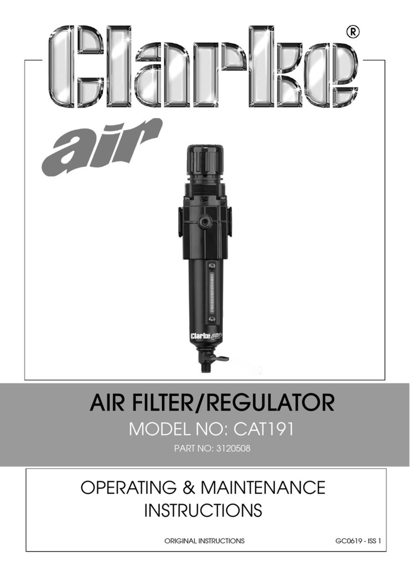
Clarke CAT191 Installation and operation manual

Clarke
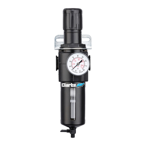
Clarke FR1 User manual
Clarke
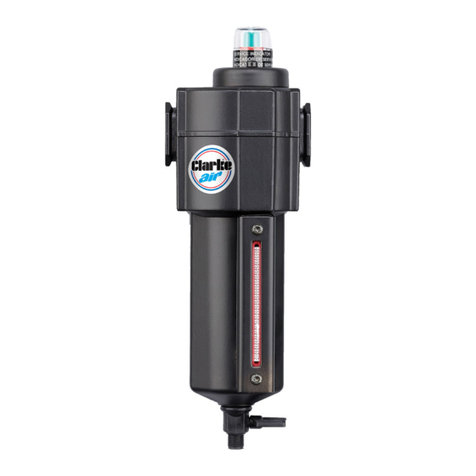
Clarke CAT197 Installation and operation manual
Clarke
Clarke CAT183 Installation and operation manual
Clarke
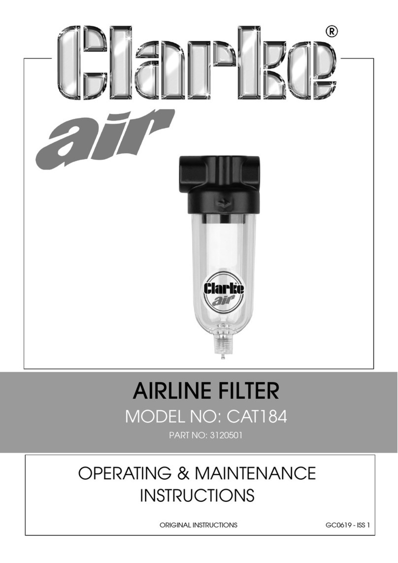
Clarke CAT184 Installation and operation manual
Clarke
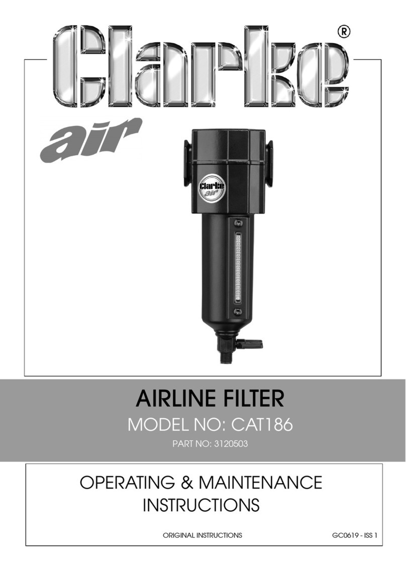
Clarke CAT186 Installation and operation manual
Clarke
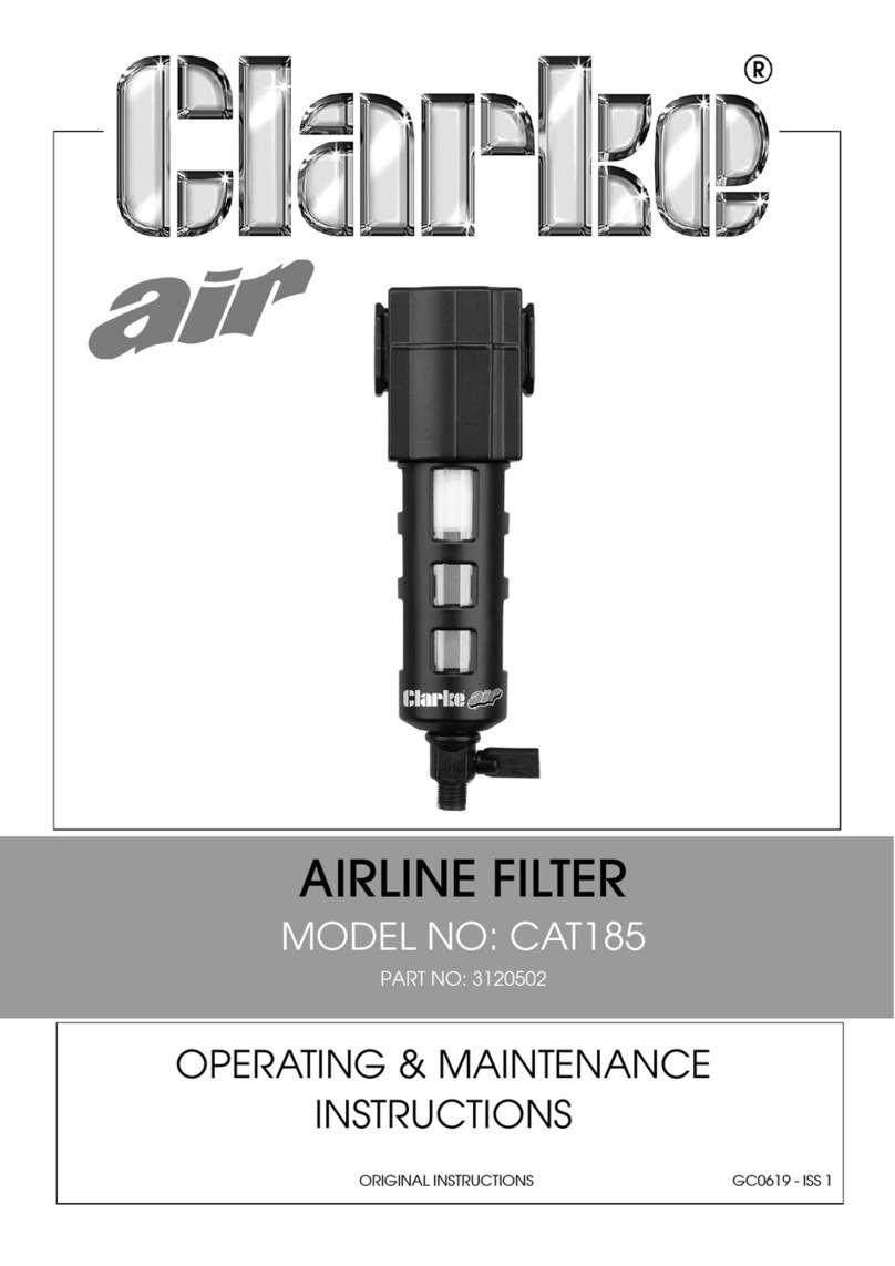
Clarke CAT185 Installation and operation manual

Clarke
Clarke CAT182 Installation and operating instructions
Clarke
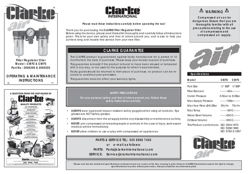
Clarke CMF2 Installation and operation manual
Clarke
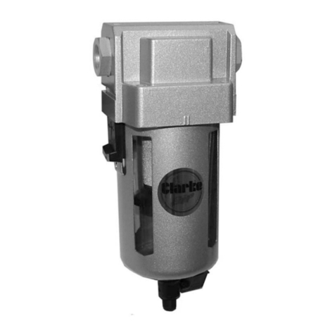
Clarke Air CAT159 Installation and operating instructions

Clarke
Clarke CAT161 Manual

Clarke
Clarke CAT192 Installation and operation manual

Clarke
Clarke CHT254 User manual
Clarke
Clarke CAT152 Instructions for use
Clarke
Clarke CAT180 Installation and operation manual
Clarke
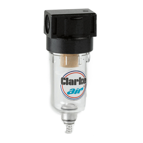
Clarke MF2 User manual
Clarke
Clarke CAT187 Installation and operation manual
Popular Water Filtration System manuals by other brands

Wisy
Wisy LineAir 100 Installation and operating instructions

Schaffner
Schaffner Ecosine FN3446 Series User and installation manual

Pentair
Pentair FLECK 4600 SXT Installer manual

H2O International
H2O International H20-500 product manual

Renkforce
Renkforce 2306241 operating instructions

Neo-Pure
Neo-Pure TL3-A502 manual


