Laskomex Bastion Apus II User manual

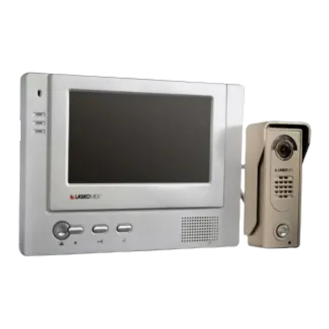
Video door phone set
Bastion Apus II

1. Safety of operation and maintenance 3
2. Purpose and characteristics of video door phone set 3
3. Elements of Apus II video door phone set 4
- MVC-7002 monitor 4
- BVC-6504 external panel 4
- feeder KSAD 1500120W1EU or GP005E-150-100 5
- Electro-catch 5
- Electro-catch feeder 5
4. Before the assembly 5
- Specify the places where elements are to be mounted 5
- Electric installation of video door phone 6
- Block diagrams 7
- Connection diagrams 8
5. Assembly and connecting elements of video door phone 9
- Assembly and connection MVC-7002 monitor 9
- Connection a second monitor 9
- Assembly and connection the external panel BVC-6504 9
- Feeder assembly 10
- Assembly of electro-catch 10
6. Operating video door phone 10
7. Programming mode in external pane BVC-6504 11
8. Maintance 12
9. Technical data 13
2
LASKOMEX PPUH, ul. D¹browskiego 249, 93-231 £ód, tel. (42) 671 88 00, fax (42) 671 88 88, e-mail: [email protected], http://www.laskomex.com.pl
1. Safety of operation and maintenance
- Before installing and using the video door phone, read the assembly and operating
manual.
- Electrical installation should be made in accordance with PN-IEC 60364-1 standard
by an authorized person.
- Electrical installation should be made in such a way as to prevent exposure to direct
lightning discharge.
- Video door phone elements should be used as intended. Using video door phone
elements for other purposes, including with equipment other than specified in the
manual or connecting them in other manner than prescribed by the manufacturer may
lead to their damage, fire or electric shock.
- Do not cover the openings in the monitor housings.
- Do not insert any metal items in the openings in the monitor housing and the feeder
as it may lead to electric shock or fire.
- The external panel should be installed in a place with low noise level.
- Video door phone elements should be connected to an electrical installation when the
feeder is disconnected from the power network.
2. Purpose and characteristic of video door phone
- Video door phone APUS II is designed for single family houses, companies, institutions
and service providers.
- Two monitors may be connected to the external panel.
- To external panel you can connect additional button to opening
the door
- The video doorphone is a hands-free device featuring a colour display. The half-duplex
voice communication requires no manual channel switching: the direction is switched
by voice.
- The external panel is wall-mounted.
- Outdoor panel have a keypad to acces by user code
- The panel is equipped with a colour camera and a LED display facilitating viewing
visitors faces at night.
3
LASKOMEX PPUH, ul. D¹browskiego 249, 93-231 £ód, tel. (42) 671 88 00, fax (42) 671 88 88, e-mail: [email protected], http://www.laskomex.com.pl
3. Elements of Apus II video door phone set:
Monitor MVC-7002
This is a hands-free (loudspeaking) monitor with a 5.8" colour display with brightness,
saturation and volume adjustment, and buttons for receiving calls, turning on the camera
view and triggering the door release.
BVC-6504 outdoor panel
An anti-vandal outdoor panel featuring a colour camera, LED camera illuminator,
speaker, microphone and access keyboard with a calling button. The panel is surface-
mounted and equipped with a door strike relay activated on pressing the monitor button.
Fig 2. BVC-6504 outdoor panel
4
Fig 1. Monitor MVC-7002
Potentiometer of volume
regulation is on backside
the panel
LED indication
Screen
Microphone
Volume
Saturation Brightnes
Preview
Door release
Talk/
end talk
Speaker
CCD camera
Water cover
Keypad Access
Camera illumination
Dial button
Light sensor
LED Idication
Mic
LASKOMEX PPUH, ul. D¹browskiego 249, 93-231 £ód, tel. (42) 671 88 00, fax (42) 671 88 88, e-mail: [email protected], http://www.laskomex.com.pl
5
KSAD 1500120W1EU or GP005E-150-100 power adapted
A 15V DC/1.2A or 15V DC/1A power adapter with IP40 protection grade. It supplies
power to the monitor and indirectly powers the outdoor panel. The access keyboard
and door release will not work without connecting the door release power adapter
(KSAD1350120WE1EU). The keyboard can be used to switch off the monitor power
and open the door using user codes (see Point 7, section Combination lock operation).
The package also includes:
- monitor holding bracket
- mounting screws
- wires with connectors necessary to connect the kit
KSAD1350120W1EU door release power adapter
A 13.5V DC/1.2A power adapter which supplies power to the door release and indirectly
powers the access keyboard. The wire marked with a grey dotted line is plus, and the
solid white one is minus see the figure under the power adapter. The wires should
be connected according to the connection diagram.
Additional components not included in the basic kit:
Door release (optional not included in the basic kit)
The video doorphone should only be used with door releases rated at 13.5V DC/1A max.
When choosing the door release, take into account the mechanical design of the gate
of the door it will be installed with and the opening direction (left or right). Compatible
models include door releases from Openers&Closers (for more details, visit
www.laskomex.com.pl).
4. Before the assembly
Specify the places where video door phone elements are to be mounted.
- Mount the monitor in a place not exposed to strong light (e.g. close to the lamp,
window etc.) as it may obstruct viewing image on the screen.
- Do not mount the monitor in place where it could be exposed to humidity e.g. in
bathrooms.
- Do not mount the monitor near the sources of strong electromagnetic interference
(wiring, TV sets etc.)
- Do not mount the monitor in heating sources - stoves, radiators etc.
- The external panel should be mounted in such a place that the camera lens is not
directed to light source (sun, strong lamp post) because it will significantly obstruct
Rys 3. KSAD 1500120W1EU or GP005E-150-100
Pin to J100 socket
(power supply)
+
-
red
black
with dashed line
all black
LASKOMEX PPUH, ul. D¹browskiego 249, 93-231 £ód, tel. (42) 671 88 00, fax (42) 671 88 88, e-mail: [email protected], http://www.laskomex.com.pl
or prevent viewing the visitors' faces.
- The image on the screen depends on the height the panel is mounted at. The
recommended height is ca. 150 cm. Such height allows for viewing the face of an
adult of average height standing ca. 50 cm from the panel. The assembly height should
be determined on a trial basis.
- Do not mount the external panel at the distance exceeding 100 m from monitor (with
the appropriate cable sections).
- Mount the feeder inside, in a place not exposed to humidity.
- The above recommendations relate to both the monitor feeder and door strike feeder.
The door strike feeder may be mounted near the external panel (e.g. in the installation
box of fence pillar).
Electric installation of video door phone.
Elements of video door phone may be connected with any cable with section meeting
the requirements specified in Table 1.
Coaxial cable75 should be used to transmit video signal. The coaxial cable should
be connected as presented in Figure 7.
The maximum distance between the external panel and the monitor should not exceed
100 m.
To put down in the ground and outside the room it is necesarry to use the damp-proof
cables. The number of wires in the cables is shown on the single line diagram (fig. 4).
NOTE: It is necessary to pay special attention on quality of connection`s wires and also
on proper isolation of every connection especially when weather conditions
appears. It is recommended to use hermetic cable box and shrink wrap in the
place of joint the wires.
Maladjustment to those recommendation may lead to the impropriety activity
of the door phone set.
Table 1. Minimum cable section according to the distance between door phone elements
6
+Vcc,masa,audio
video
video
+Vcc,masa,audio
0,2mm2
<20m <50m
0,44mm2
Coaxial cable
<100m
1mm21.5mm2
maximum 4m,
Distance
Connection
outdoor station - monitor
power adapter - outdoor station,
power adapter - monitor
Power adapter - 230V
monitor - monitor
1mm2
0,75mm2
Coaxial
cable
0,2mm2
LASKOMEX PPUH, ul. D¹browskiego 249, 93-231 £ód, tel. (42) 671 88 00, fax (42) 671 88 88, e-mail: [email protected], http://www.laskomex.com.pl
7
Figure 5. Block diagram of connecting elements of Apus II video door phone
Figure 4. Connection of Apus II video door phone - single line diagram.
b) How to youse clamps in external panel.
MVC-7002
+ -~ ~
BVC-6504
J102J100
Electro-catch
Clamps in external panel
2
230V 2
4
Optional - connecting
second monitor
BVC-6504
Electro-catch
*
MVC-7002
~230V
~230V
2
2
2
2
2
4
MVC-7002*
KSAD 1500120W1EU lub
GP005E-150-100*
KSAD 1500120W1EU or
GP005E-150-100
CAUTION!!
The orders of terminals in
BVC-6504 is changed
KSAD 1350120W1EU
KSAD 1350120W1EU
KSAD 1500120W1EU or
GP005E-150-100
b)
Description of clamps with connected
electro-catch
1) Push Down
2) Wires
How to use clamps
in external panel
white(WIDEO)
red(AUDIO)
blue(MASA)
yellow(Vcc+)
Monitor Outdor station
clamps on
backside
of panel
AUDIO
VIDEO
Przycisk
-VDC
Styk NO
+VDC
+12V
GND
Opening
button
Elektrozaczep
DC13,5V/
1,2A
+
-
Power suply
+ -
230V AC 15V DC/1.2A
~ ~
230V AC
13,5V DC/1,2A
+ -
audio video
White
Yellow
Red
Blue
+Vcc
masa
audio video
NO
+VDC za.
+12V
za.
GND
PRZ.
-VDC
White
Yellow
Red
Blue
Red
Black
* not include in the set
LASKOMEX PPUH, ul. D¹browskiego 249, 93-231 £ód, tel. (42) 671 88 00, fax (42) 671 88 88, e-mail: [email protected], http://www.laskomex.com.pl
8
Figure 6. Block diagram of connecting elements of Apus video door phone with additional monitor
MVC-7002
+ -~ ~
BVC-6504
J102J100
Clamps in external panel
J100
MVC-7002
J102
KSAD 1500120W1EU or
GP005E-150-100
CAUTION!!
The orders of terminals in BVC-6504 is changed
KSAD 1350120W1EU
Electro-catch
KSAD 1500120W1EU lub
GP005E-150-100
+ -
230V AC 15V DC/1,2A
~ ~
230V AC
13,5V DC/1,2A
+ -
masa
audio video
audio video
NO
+VDC za.
+12V
za.
GND
PRZ.
-VDC
+Vcc
-
230V AC 15V DC/1,2A
+
+ -~ ~
masa
audio video
+Vcc
Red
Blue
Yellow
White
Red
Blue
Yellow
White
Red
Back
Red
Black
Red
Blue
Yellow
White
LASKOMEX PPUH, ul. D¹browskiego 249, 93-231 £ód, tel. (42) 671 88 00, fax (42) 671 88 88, e-mail: [email protected], http://www.laskomex.com.pl
5. Installing and connecting the video doorphone components
Installing and connecting the MVC-7002 monitor
For easier installation, all the wires of the video doorphone can be run to a standard
cable box installed in the wall. Once mounted, the monitor should cover the whole box.
This will make it easier to install and mount the monitor.
- The monitor is mounted on a metal holding bracket fixed to the wall. To fix the bracket,
place it against the wall in the intended place of installation and mark holes for rawl
plugs.
- Drill the holes as market and fix the bracket to the wall using rawl plugs.
- Connect the wires to the J102 socket connector provided with the kit, as shown in the
diagram, by soldering them to the wiring system. Protect all soldered connections and
isolated portions of the wires against short-circuit with a shrinking sleeve or insulating
tape. Plug the connectors to the sockets.
- Mount the monitor on the holding bracket.
Installing and connecting the additional monitor
For connecting two MVC-7002 monitors to a single outdoor panel, run a separate power
supply (J100 socket) to the additional monitor and connect the two monitors. See Figure
4, 5 and 6 (p.7, 8)
Fig 7.
Connectors in
MVC-7002 monitor
9
Pin to J102 socket
(
optional - connection
additional external panel
)
Pin to J103 socket
(
optional - connection
additional external panel
)
Pin to J100 socket
(power supply)
red
+
black
-
red
audio
white
wideo
yellow
Vcc+
blue
masa
red
audio
white
wideo
yellow
Vcc+
blue
masa
Installing and connecting the BVC-6504 outdoor panel.
- Unscrew the screw holding the panel to the hood.
- Place the hood at the intended place of installation, mark holes for the rawl plugs and
drill the holes (Fig. 8b, p. 10). The camera lens should be placed at a height of approx.
150 cm (see Fig 8a, p. 10).
- Pull the wiring system cable through the circular hole in the casing and fasten the
casing to the wall (Fig. 8c, p. 10).
- Connect the wires according the diagram (see Fig. 5, p. 7). As shown in Fig. 5, the
LASKOMEX PPUH, ul. D¹browskiego 249, 93-231 £ód, tel. (42) 671 88 00, fax (42) 671 88 88, e-mail: [email protected], http://www.laskomex.com.pl

Installing and connecting the power adapter
The wire marked with a grey dotted line is plus, and the solid white one is minus see
Fig. 3. The wires should be connected according to the connection diagram.
Installing and connecting the door release
The door release is controlled by the relay in the outdoor panel and must be powered
from a separate DC power adapter.
Install the door release in the gate or the entrance door according to the manufacturer's
recommendations. Then proceed to connect the wires in the outdoor panel (two black
wires), power adapter wires and the door release, as shown in the connection diagram
(see Figures 5, 6).
Fig. 7. Outdoor panel installation
6. Video doorphone operation
- Pressing the calling button ( ) on the outdoor panel triggers a calling signal in the
monitor and switches on the camera view (if an additional monitor has been installed,
the camera view will display on both monitors).
- To switch on voice communication, press the button (talk, see Fig. 1). In two-monitor
installations, if voice communication has been established by one of the monitors, the
other one will switch off after approx. 1minute.
- If voice communication is not activated after calling, the monitor will automatically switch
off after approx. 1 minute.
- The talk time is limited to approx. 120 seconds, after which the phone will automatically
hang up.
- To hang up, press the button (talk) again.
wires should be connected to the outdoor panel with snap-on connectors (see Fig.
4b, p. 7). Place the panel against the hood and secure it with the mounting screw
(Fig. 8D, p. 10).
10
Pin to J100 socket
(power supply)
Fig. 8. Power socket connector of the monitor
View side
150cm
red
+
black
-
LASKOMEX PPUH, ul. D¹browskiego 249, 93-231 £ód, tel. (42) 671 88 00, fax (42) 671 88 88, e-mail: [email protected], http://www.laskomex.com.pl
- The door release can be activated at any time during the conversation by pressing
the button on the monitor. The release continues while the button remains pressed.
- The camera view on the monitor can be switched on at any moment by pressing the
button (view). Pressing the button again will switch the view to the next entrance,
and pressing the button yet again will switch off the camera view.
- sequential operation. To activate voice communication in the camera view mode,
press the button (talk).
- The MVC-7002 monitor features controls for volume, brightness and colour saturation
adjustment (seeFig.1).
ATTENTION!
The camera view is activated with a delay of approx. 2 seconds after pressing the
View/Talk button.
7. Programming mode in panel BVC-6504
Entering programming mode
1) press *, you will hear 2 short sounds
2)enter your 4 digit administrator code, you will hear 3 short sounds, red LED is flashing
you are now in programming mode
3) to exit programming mode press the * key.
Adding user codes
1)press *, you will hear 2 short sounds
2)enter your 4 digit administrator code, you will hear 3 short sounds, red LED is flashing
you are now in programming mode
3)enter the location 01 to 40 (31-40 are the latching code locations). If a series of bleeps
are heard at this point then the location has a code stored, you may proceed as this
is only a warning.
4)enter the desired 4 digit user code, if the code lock retunes immediately to the
programmiong mode base level then the code is not permitted as it already exits else
where in another locations, if the code is permitted then you will hear 3 short sounds
5)return to step 2 to enter more user codes or press the * key to exit programming
mode.
ATTENTION!
In default configuration is not programmed any user code.
DELETING USER CODES
1)press *, you will hear 2 short sounds
2)enter your 4 digit administrator code, you will hear 3 short sounds, red LED is flashing
you are now in programming mode
3)enter user location (01-40), you will hear 3 short sounds
4)press button #, you will hear 3 short sounds
5)return to step 3 to delete more codes or press the * key to exit programming mode.
11
LASKOMEX PPUH, ul. D¹browskiego 249, 93-231 £ód, tel. (42) 671 88 00, fax (42) 671 88 88, e-mail: [email protected], http://www.laskomex.com.pl
8. Video doorphone maintance
Components of the video doorphone should be cleaned with a wet cloth or with cleaning
agents designed for plastics.
ATTENTION!
Do not use solvents or abrasive cleaners, as they can result in permanent damage to
the surface of the casing! Avoid any contact of doorphone components with water or
cleaning agents, as this might result in damaging the device and electric shock!
12
Reset (without administrator code)
1) press *, you will hear 2 short sounds
2)enter your 4 digit administrator code, you will hear 3 short sounds, red LED is flashing
3) press #,you will hear 2 short sounds, LED is flashing
4) again press #,you will hear 2 short sounds, LED is flashing
5) press # 7 times , you will hear 5 short sounds, LED is off
Operation lock with code
1) enter your 4 digit user code,
2) The red LED is lit this means user code is correct (door open)
3) Led diode turn off , 6 short sounds (door locked)
ATTENTION!! If code is entered incorrect 3 times the operation of opening door
by code is blocked (about 1min). Blocade is signaling by means of external panel
you will hear long sound.
CHANGING THE ADMINISTRATOR CODE
1)remove power from the unit and press and hold down the * key
2)apply power whilst holding button down, the unit will then give long continuous sound.
3)when the tone has stoped, release the * key and enter your new 4 digit administrator
code
LASKOMEX PPUH, ul. D¹browskiego 249, 93-231 £ód, tel. (42) 671 88 00, fax (42) 671 88 88, e-mail: [email protected], http://www.laskomex.com.pl

9. Technical data
Monitor MVC-7002
Screen size 5,8
Dimension 220x110x28mm
Supply voltage 15V DC/0.8A
Operation temperature 0°C...40°C
BVC-6503 external panel
Dimension 182x75x60mm
Operation temperature -20°C...55°C
Degree of protection IP43
Angle of view vertical/horizon 36°/48°
Power supply KSAD 1500120W1EU or GP005E-150-100
Input voltage 230V AC 230V AC
Output voltage 15V DC/1,2A max. 15V/1A
Dimension 81x43x67 81x43x67
Operation temperature 0°C...40°C 0°C...40°C
Degree of protection IP40 IP40
13
LASKOMEX PPUH, ul. D¹browskiego 249, 93-231 £ód, tel. (42) 671 88 00, fax (42) 671 88 88, e-mail: [email protected], http://www.laskomex.com.pl

Notes:

Notes:

This product was marked with a symbol of crossed dustbin
according to European Directive 2002/96/WE on used electric
and electronic equipment. Used equipment cannot be placed
with other wastes from households. Product user is obliged to
give it to the firm which collects used electronic or electric
equipment such as local collection points, shops, places appointed
by the producer or commune waste collection units.
INSTRUCTION ON ENVIRONMENT PROTECTION
List of collecting units of used Laskomex equipment is available on www.laskomex.com.pl
website or telephone No. 42 671 88 68.
Product packing should be removed according to environment protection regulations.
Remember!
Selective collection and recycling of used electronic and electric equipment
considerably contributes to the protection of human health and life as well as
protection of natural environment.
Return of packaging materials for the material recycling saves raw materials and
reduces generating of wastes.
V1.0 2013-12-11
ul. D¹browskiego 249, 93-231 £ód, tel. 42 671 88 00, fax 42 671 88 88
Table of contents
Other Laskomex Intercom System manuals

Laskomex
Laskomex CD-3100 Series Installation manual

Laskomex
Laskomex Bastion Orion II User manual

Laskomex
Laskomex Bastion Draco User instructions

Laskomex
Laskomex EC-2502 Owner's manual

Laskomex
Laskomex CD-2000 Installation manual

Laskomex
Laskomex Bastion Draco II User manual

Laskomex
Laskomex CP-2502 Series User manual

Laskomex
Laskomex Bastion libra User instructions

Laskomex
Laskomex Bastion Apus User manual

Laskomex
Laskomex CD-2000 Installation manual