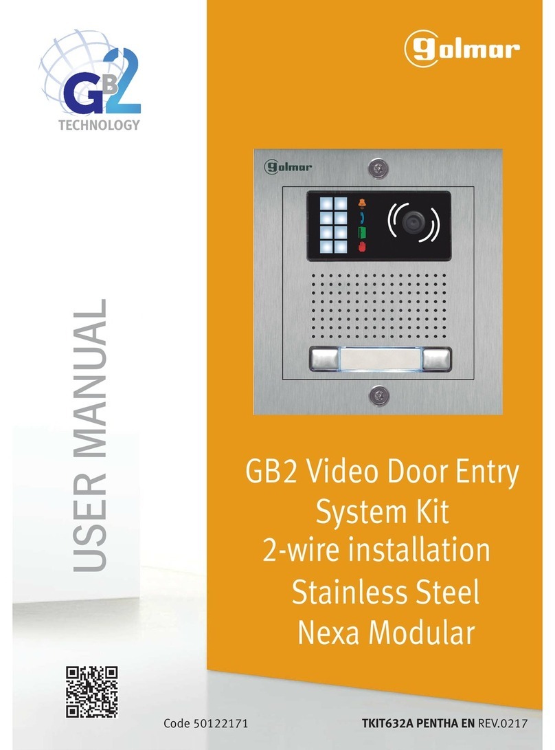
golmar ROCK INOX User manual

15
Audio and Video
door entry system
Installation annex
ROCK INOX
TROCK INOX ML rev.0112
Cód. 50120111

17
INTRODUCTION
First of all we would like to thank and congratulate you for the purchase of this product manufactured by
Golmar.
The commitment to reach the satisfaction of our customers is stated through the ISO-9001 Certification
andforthemanufacturingofproductslikethisone.
Its advanced technology and exacting quality control will do that customers and users enjoy with the
legion of features this system offers. To obtain the maximum profit of these featuresand a properly wired
installation,wekindlyrecommendyoutoexpendafewminutesofyourtimetoreadthismanual.
Introduction............................................................................................................................17
Index .....................................................................................................................................17
Important...............................................................................................................................17
Installation .............................................................................................................................18
4+Nsysteminstallation.........................................................................................................18
2Plussysteminstallation.........................................................................................................19
V2Plussysteminstallation.......................................................................................................20
VistaPlussysteminstallation ...................................................................................................21
Plussysteminstallation...........................................................................................................22
INDEX
IMPORTANT
OSeeuser manualcorresponding fordetails ofconnection andprogramming system.
OUsermanual reference:
w4+Nsystem: Usermanual T555ML.
w4+Ngeneral doorpanel system:User manualT505ML.
w2Plussystem: Usermanual T2PlusML.
wV2Plussystem: Usermanual TV2PlusML.
wVistaPlus system:User manualTR5ML.
wPlussystem: Usermanual T500SEML/T1ML.
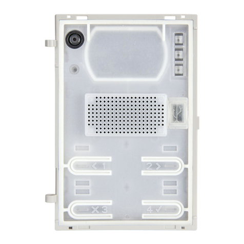
OBefore insert the sound module in the door panel, brake the light push button by
simplypressing itwith helpof apair ofpliers, asit isshown onthe drawing.
18
SeeusermanualT555MLfordetailsofconnectionofthepush-buttons.
Do not removes the visor chamber (camera).
4+N SYSTEM INSTALLATION
ush buttons and lamps wiring, 4+N system.
P
Uses the bracket SUP-EL500 in general door panel system for the placement of the
microprocessormoduleEL505intheembeddingbox.
Up to 20 Ind. with Rock Inox 7220 door panel.
L2
EL-555
CP
Ind.1
Ind.3
Ind.5
Ind.7
Ind.9
Ind.2
Ind.4
Ind.6
Ind.8
Ind.10
P_CV ~2 ~1
CN1
L1
Plug the push buttons connecting wires in the CN4 connector of the sound module
EL520, this wire consists of 10 conductors (P1 to P8, B and CP) for the push
buttonsconnectionorencodercircuitsEL516SE.
SeeusermanualT2PlusMLfordetailsofconnectionofthepush-buttons.
Do not removes the visor camera.
2PLUS SYSTEM INSTALLATION 19
ush buttons and lamps wiring, 2Plus system.
P
Uses the SUP-EL516 bracket for the placement of the encoder circuit EL516SE or
thecurrentconvertermoduleEL502intheembeddingbox.
Towards other encoders or push buttons.
Plug the push buttons connecting wires in the CN6 connector of the EL500/V2Plus
microprocessormodule,thiswireconsistsof10conductors(P1toP8,BandCP)for
thepushbuttonsconnectionorencodercircuitsEL516SE.
SeeusermanualV2PlusMLfordetailsofconnectionofthepush-buttons.
FirstremovesthevisorcamerabeforeplacingthesoundmoduleEL530/EL531.
V2PLUS SYSTEM INSTALLATION
20
ush buttons and lamps wiring, V2Plus system.
P
Uses the SUP-EL500 bracket for the placement of the microprocessor module
EL500/V2Plus and the SUP-EL516 bracket for the placement of the encoder
circuitEL516SEintheembeddingbox.
Towards other encoders or push buttons.
( ) No function.
**
EL-516SE
BCP P
CN1
EL516SE
Connector detail CN2
CN2 CN3
CP:
B: Red
P9: Green
P10: Orange
P11: Blue
Black P12: Violet
P13: Yellow
P14: White
P15: Brown
: Grey ( )
EL516SE
Connector detail CN3
B
CP
CN4
P5
P6
P7
P8
P4
P3
CP
P8
B
P7
P1
P6
P2
P5
P3
P4
Top view
CP: Black
B: Red
P1: Green
P2: Orange
P3: Blue
P4: Violet
P5: Yellow
P6: White
P7: Brown
P8: Grey
Colors code:
CP
P8
B
P7
P1
P6
P2
P5
P3
P4
Top view
CP:
B: Red
P1: Green
P2: Orange
P3: Blue
Black P4: Violet
P5: Yellow
P6: White
P7: Brown
P8: Grey
CP B
P15
P9
P14
P10
P13
P11
P12
Top view
EL520
Connector detail CN4
**
CV1 +12
EL-520
+_CV2
BUS
L1 L2
Colors code: Colors code:
EL-500/V2Plus
+_CV2CV1 +12BUS
EL-516SE
BCP P
CN1
CN2 CN3
B
CP
CN6
P5
P6
P7
P8
P4
P3
CP
P8
B
P7
P1
P6
P2
P5
P3
P4
Top view
CP:
B: Red
P1: Green
P2: Orange
P3: Blue
Black P4: Violet
P5: Yellow
P6: White
P7: Brown
P8: Grey
Colors code:
EL500/V2PLUS
Connector detail CN6
( ) No function.
**
EL516SE
Connector detail CN2
CP:
B: Red
P9: Green
P10: Orange
P11: Blue
Black P12: Violet
P13: Yellow
P14: White
P15: Brown
: Grey ( )
EL516SE
Connector detail CN3
CP
P8
B
P7
P1
P6
P2
P5
P3
P4
Top view
CP:
B: Red
P1: Green
P2: Orange
P3: Blue
Black P4: Violet
P5: Yellow
P6: White
P7: Brown
P8: Grey
CP B
P15
P9
P14
P10
P13
P11
P12
Top view
**
Colors code: Colors code:

Plug the push buttons connecting wires in the CN4 connector of the sound module
EL520, this wire consists of 10 conductors (P1 to P8, B and CP) for the push
buttonsconnectionorencodercircuitsEL516SE.
SeeusermanualT2PlusMLfordetailsofconnectionofthepush-buttons.
Do not removes the visor camera.
2PLUS SYSTEM INSTALLATION 19
ush buttons and lamps wiring, 2Plus system.
P
Uses the SUP-EL516 bracket for the placement of the encoder circuit EL516SE or
thecurrentconvertermoduleEL502intheembeddingbox.
Towards other encoders or push buttons.
Plug the push buttons connecting wires in the CN6 connector of the EL500/V2Plus
microprocessormodule,thiswireconsistsof10conductors(P1toP8,BandCP)for
thepushbuttonsconnectionorencodercircuitsEL516SE.
SeeusermanualV2PlusMLfordetailsofconnectionofthepush-buttons.
FirstremovesthevisorcamerabeforeplacingthesoundmoduleEL530/EL531.
V2PLUS SYSTEM INSTALLATION
20
ush buttons and lamps wiring, V2Plus system.
P
Uses the SUP-EL500 bracket for the placement of the microprocessor module
EL500/V2Plus and the SUP-EL516 bracket for the placement of the encoder
circuitEL516SEintheembeddingbox.
Towards other encoders or push buttons.
( ) No function.
**
EL-516SE
BCP P
CN1
EL516SE
Connector detail CN2
CN2 CN3
CP:
B: Red
P9: Green
P10: Orange
P11: Blue
Black P12: Violet
P13: Yellow
P14: White
P15: Brown
: Grey ( )
EL516SE
Connector detail CN3
B
CP
CN4
P5
P6
P7
P8
P4
P3
CP
P8
B
P7
P1
P6
P2
P5
P3
P4
Top view
CP: Black
B: Red
P1: Green
P2: Orange
P3: Blue
P4: Violet
P5: Yellow
P6: White
P7: Brown
P8: Grey
Colors code:
CP
P8
B
P7
P1
P6
P2
P5
P3
P4
Top view
CP:
B: Red
P1: Green
P2: Orange
P3: Blue
Black P4: Violet
P5: Yellow
P6: White
P7: Brown
P8: Grey
CP B
P15
P9
P14
P10
P13
P11
P12
Top view
EL520
Connector detail CN4
**
CV1 +12
EL-520
+_CV2
BUS
L1 L2
Colors code: Colors code:
EL-500/V2Plus
+_CV2CV1 +12BUS
EL-516SE
BCP P
CN1
CN2 CN3
B
CP
CN6
P5
P6
P7
P8
P4
P3
CP
P8
B
P7
P1
P6
P2
P5
P3
P4
Top view
CP:
B: Red
P1: Green
P2: Orange
P3: Blue
Black P4: Violet
P5: Yellow
P6: White
P7: Brown
P8: Grey
Colors code:
EL500/V2PLUS
Connector detail CN6
( ) No function.
**
EL516SE
Connector detail CN2
CP:
B: Red
P9: Green
P10: Orange
P11: Blue
Black P12: Violet
P13: Yellow
P14: White
P15: Brown
: Grey ( )
EL516SE
Connector detail CN3
CP
P8
B
P7
P1
P6
P2
P5
P3
P4
Top view
CP:
B: Red
P1: Green
P2: Orange
P3: Blue
Black P4: Violet
P5: Yellow
P6: White
P7: Brown
P8: Grey
CP B
P15
P9
P14
P10
P13
P11
P12
Top view
**
Colors code: Colors code:

VISTA PLUS SYSTEM INSTALLATION 21
Plug the push buttons connecting wires in the CN2 connector of the EL500/R5
microprocessor module, this wire consists of 10 conductors (P1 to P8, B and CP)
forthepushbuttonsconnectionorencodercircuitsEL516SE.
SeeusermanualTR5MLfordetailsofconnectionofthepush-buttons.
FirstremovesthevisorcamerabeforeplacingthesoundmoduleEL530/EL531.
ush buttons and lamps wiring, Vista Plus system.
P
Uses the SUP-EL500 bracket for the placement of the microprocessor module
EL500/R5 and the SUP-EL516 bracket for the placement of the encoder circuit
EL516SEorthecurrentconvertermoduleEL502intheembeddingbox.
PLUS SYSTEM INSTALLATION
22
Plug the push buttons connecting wires in the CN6 connector of the EL500SE
microprocessor module, this wire consists of 10 conductors (P1 to P8, B and CP)
forthepushbuttonsconnectionorencodercircuitsEL516SE.
SeeusermanualT500SEMLfordetailsofconnectionofthepush-buttons.
FirstremovesthevisorcamerabeforeplacingthesoundmoduleEL530/EL531.
ush buttons and lamps wiring, Plus system.
P
EL-500/R5
CV2
CN1
___++
CV1+12 A/D VI+VI- VO+VO-
EL-516SE
BCP P
CN1
CN2 CN3
B
CP
CN2
P5
P6
P7
P8
P4
P3
EL-516SE
BCP P
CN1
CN2 CN3
B
CP
CN6
P5
P6
P7
P8
P4
P3
EL-500SE
CN2
DA
OUT A
IN V
IN- V
IN+ Malla V
OUT+ V
OUT-
+_
CV1CV2
_+12
Towards other encoders or push buttons.
CP
P8
B
P7
P1
P6
P2
P5
P3
P4
Top view
CP: Black
B: Red
P1: Green
P2: Orange
P3: Blue
P4: Violet
P5: Yellow
P6: White
P7: Brown
P8: Grey
Colors code:
EL500/R5
Connector detail CN2
Uses the SUP-EL500 bracket for the placement of the microprocessor module
EL500SE and the SUP-EL516 bracket for the placement of the encoder circuit
EL516SEorthecurrentconvertermoduleEL502intheembeddingbox.
Towards other encoders or push buttons.
CP
P8
B
P7
P1
P6
P2
P5
P3
P4
Top view
CP:
B: Red
P1: Green
P2: Orange
P3: Blue
Black P4: Violet
P5: Yellow
P6: White
P7: Brown
P8: Grey
Colors code:
EL500SE
Connector detail CN6
( ) No function.
**
EL516SE
Connector detail CN2
CP:
B: Red
P9: Green
P10: Orange
P11: Blue
Black P12: Violet
P13: Yellow
P14: White
P15: Brown
: Grey ( )
EL516SE
Connector detail CN3
CP
P8
B
P7
P1
P6
P2
P5
P3
P4
Top view
CP:
B: Red
P1: Green
P2: Orange
P3: Blue
Black P4: Violet
P5: Yellow
P6: White
P7: Brown
P8: Grey
CP B
P15
P9
P14
P10
P13
P11
P12
Top view
**
Colors code: Colors code:

www.golmar.es
Golmar se reserva el derecho a cualquier modificación sin previo aviso.
Golmar se réserve le droit de toute modification sans préavis.
Golmar reserves the right to make any modifications without prior notice.
Other golmar Intercom System manuals

golmar
golmar VESTA7 SE GB2 User manual

golmar
golmar CE-990 Plus User manual

golmar
golmar 7W/G2+ User manual

golmar
golmar m300 User manual

golmar
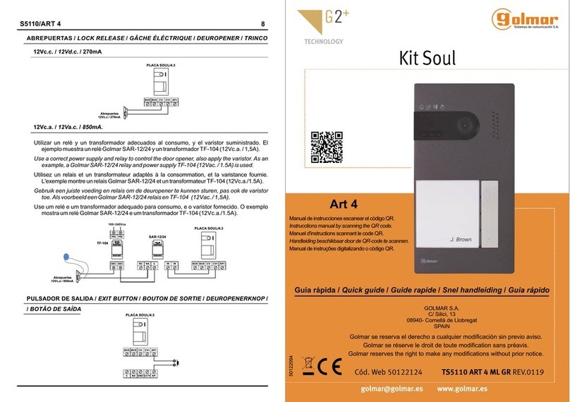
golmar G2+ Soul S5110 Art 4 User manual

golmar
golmar Stadio Plus T4003ML User manual

golmar
golmar ART 1/G+ User manual

golmar
golmar Jazz GB2 User manual

golmar
golmar CE-ART 7/G+ User manual

golmar
golmar PE295/1 User manual

golmar
golmar SV-370S User manual

golmar
golmar GB2 Nexa Modular User manual

golmar
golmar GB2 Vesta 2 User manual

golmar
golmar SV805AL User manual

golmar
golmar G2+ User manual

golmar
golmar CETK-590 Plus User manual

golmar
golmar Soul kit User manual

golmar
golmar ART 7W/G+/48 User manual

golmar
golmar T500EN User manual

golmar
golmar G2+ User manual