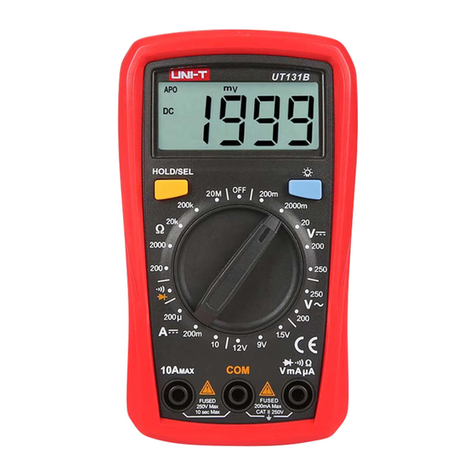
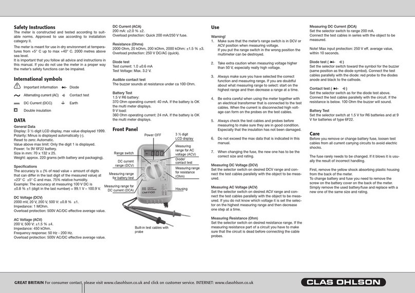
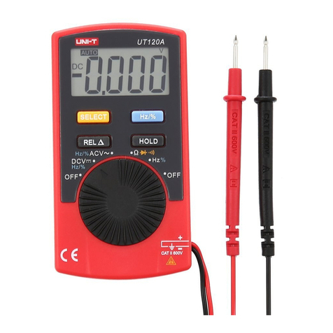
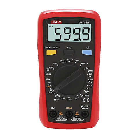
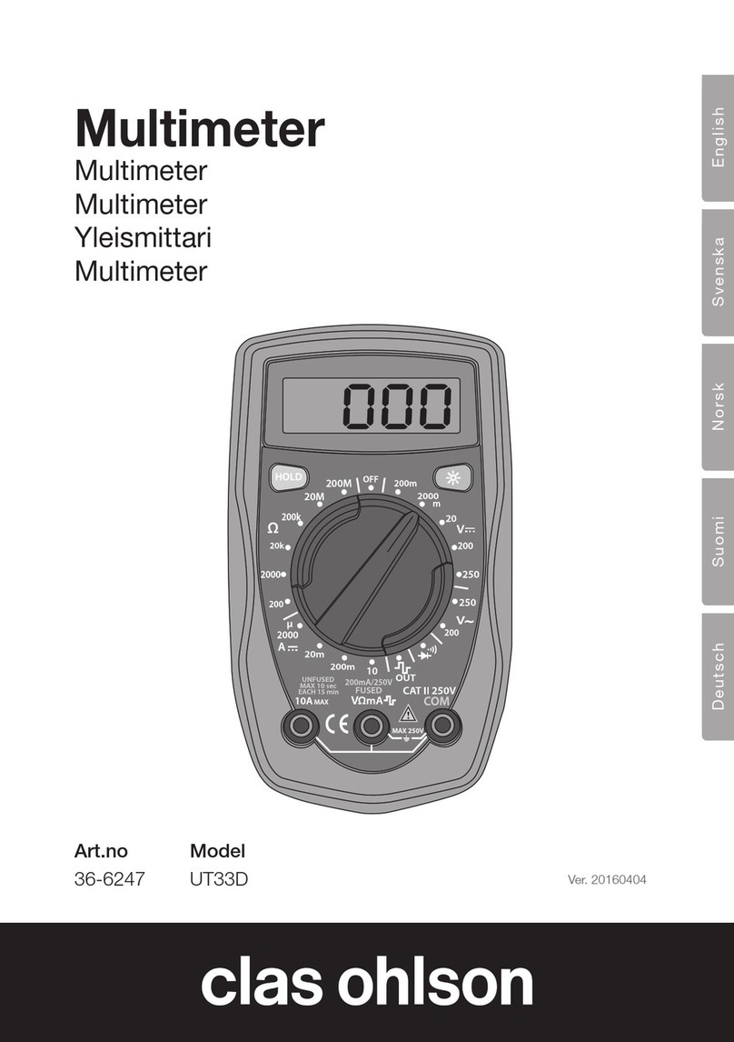
Clas Ohlson ut61d User manual

EnglishSvenskaNorskSuomiDeutsch
USB Multimeter
Multimeter medUSB
Multimeter medUSB
Yleismittari, jossaUSB
Multimeter mit USB
Art.no Model
36-4717 UT61D
English 3
Svenska 28
Norsk 53
Suomeksi 78
Deutsch 103
Ver. 20140523

2

3
English
USB Multimeter
Art.no 36-4717 Model UT61D
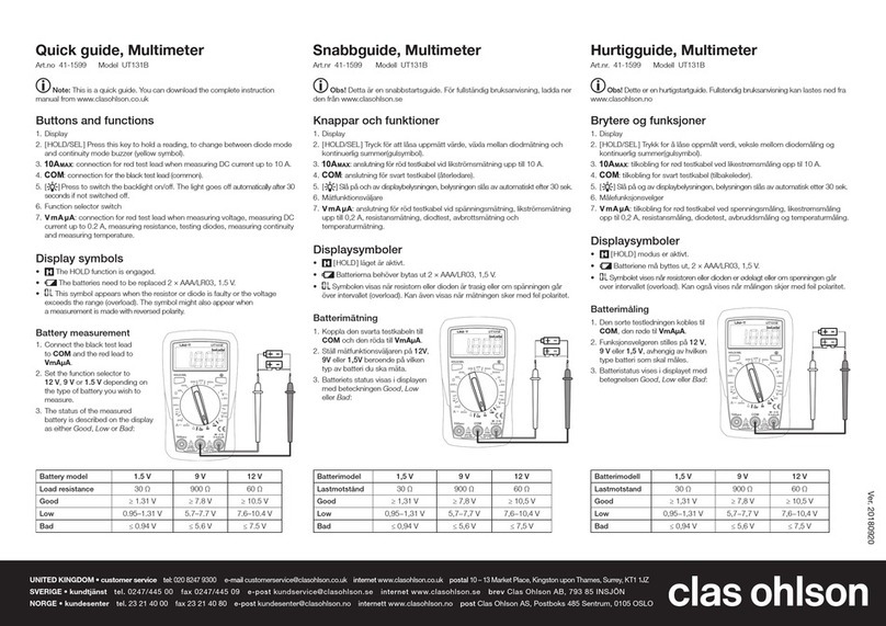
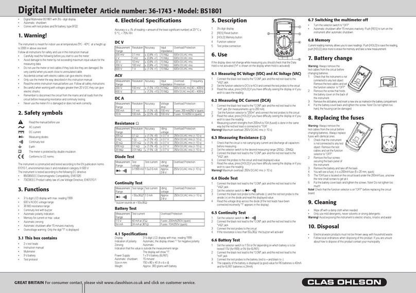
Please read theentire instruction manual before use and save it for future reference.
Wereserve theright for any errors in text or images and for making any necessary
technical changes to this document. Ifyou should have any questions concerning
technical problems please contact our Customer Services.
Table of Contents
1. Description...........................................................5
2. Safetyinstructions...............................................5
3. Package contents................................................6
4. Functions .............................................................7
4.1 Display symbols....................................................................... 8
5. Operation .............................................................9
5.1 Voltage measurement .............................................................. 9
5.2 DC and AC Current measurement......................................... 12
5.3 Resistance measurement...................................................... 13
5.4 Continuity testing................................................................... 14
5.5 Diode testing.......................................................................... 15
5.6 Capacitance measurement ................................................... 16
5.7 Frequency measurement....................................................... 17
5.8 Holdmode.............................................................................. 17
5.9 Backlight ................................................................................ 17
5.10 Relative measurement ......................................................... 18
5.11 Sleep mode (automatic shut-off)......................................... 18

4
English
6. Installing thesoftware .......................................18
6.1 Installation.............................................................................. 18
6.2 Operation................................................................................ 19
6.3 Screen .................................................................................... 21
7. Changing thebattery.........................................22
8. Fuses.................................................................. 23
8.1 Checking thefuses ................................................................ 23
8.2 Changing thefuses................................................................ 23
9. General specifications.......................................24
9.1 Accuracy ................................................................................ 24
10.Electrical specifications ................................... 25
10.1 AC Voltage............................................................................ 25
10.2 DC Voltage............................................................................ 25
10.3 DC Current............................................................................ 25
10.4 AC Current............................................................................ 26
10.5 Resistance............................................................................ 26
10.6 Capacitance ......................................................................... 26
10.7 Frequency............................................................................. 27
10.8 DiodeTest............................................................................. 27
10.9 Continuity Test ..................................................................... 27

5
English
1. Description
• Advanced TRUE-RMS multimeter with USB and RS232 connectors that let you
save and analyse your readings in your computer.
• Measuring functions: AC, DC, capacitance and frequency measurements,
diodetest and buzzer.
• Automatic shut-off.
• Optical interface for PC connection.
• Rugged, rubber-clad shock-absorbent case.
• Comes with test leads, 9 V battery, USB cable, serial cable and PC software.
• Size: 180×87×47 mm.
2. Safetyinstructions
• The multimeter has been tested in accordance with the EMC Directive 2004/108/EC
and the Low Voltage Directive 2006/95/EG, and fulfils installation category
(overvoltage category) III 1000 V, IV 600 V contamination level 3 in accordance with
EN 61010–1:2010 and EN61010-031:2002/A1:2008.
• This meter is designed for indoor use at working temperatures in therange
of0–40°C.
• Make sure that themeter is used safely by following thesafety instructions and
operating directions written in this instruction manual.
• Do not use this meter if it or thetest leads appear to be damaged, or if you
suspect that themeter might not work properly.
• Make sure that your fingers are behind thefinger guards when using thetestleads.
• Make sure that thepower is turned off before working on thepower circuit.
Evenlow voltages can be dangerous!
• Do not measure voltages higher than 600 VDC or 600 VAC RMS between apower
point and earth connection.
• To avoid shocks you need to be CAREFUL when you work with voltage higher
then 60 VDC or 30 VAC RMS. Voltages higher than this pose arisk of heavy
electric shocks.
• Set theright measuring range using theselector before starting to measure and do
not change therange whilst taking ameasurement.
• Never use themeter if thebattery cover is missing or thebattery compartment
isopen.
• To avoid electric shocks and damage to themeter, do not exceed theoverload
limits. Theguarantee is void if themeter is used incorrectly.
• This meter is protected by fuses, but they will not protect themeter from all kinds
of misuse.
• The meter must not be used in humid, explosive or flammable environments or
close to strong magnetic fields.
• Replace thebattery immediately if thebattery warning symbols appears on thedisplay.
Aweak battery can cause incorrect results and thereby pose asafety hazard.
6
English
• Neither themeter nor its accessories may be dismantled or modified in anyway.
• This meter is only intended for indoor use.
• Remove thebattery from themeter if it is not to be used for anextended period.
• Turn themeter off afteruse.
• If themeter is placed close to astrong magnetic field it might cause incorrect
readings which can be corrected by removing thecause of theinterference.
3. Package contents
• Multimeter (with battery)
• 2 x testleads
• USBcable
• RS232C cable
• UT61 multi-purpose socket
• Instruction manual
• CD-ROM software disc
• Case

7
English
1
3
4
5
7
2
6
8
9
10
11
12
4. Functions
1. LCD display
2. [Max Min]
– Pressto switch between max and min measured value.
– Holdin for two seconds to return to normal display.
3. [Range]
– Pressonce to enter manual settings mode; thebuzzer sounds once.
– Pressrepeatedly to advance through themeasuring ranges; thebuzzer sounds.
– Holdin for two seconds to return to Autorange (automatic measuring
rangesetup).
4. [Hold/Light]
– Pressto save areading (data hold function), press once more to delete
thereading.
– Holdin for two seconds to turn on thedisplay backlight for 10 seconds.
5. Multifunction selector
8 different measuring functions and off switch.
6. Testlead sockets
7. Testlead sockets

8
English
8. [REL ▲/RS 232 (USB)]
– Pressonce to enter RELmode.
– Pressonce to exit RELmode.
– Holdin for two seconds to activate or deactivate theRS232/USB function.
Thesleep function is exited when theRS232/USB function is activated and
disappears from thedisplay.
9. [Hz %]
– Pressto measure frequency.
– Pressto select Duty Cyclevalue.
10. Alternative functions (blue button)
Press to select alternative functions for thesettings modes in blue.
11. Testlead sockets
12. Testlead sockets
4.1 Display symbols
Thedata hold function is activated.
Thesleep mode is activated.
Indicates anegative reading.
Indicator for AC measurement.
Indicator for DC measurement.
TheAutorange is activated (meter automatically selects therange with
bestresolution).
Indicator for manual range mode (not on this model).
Thereading is too high for this measuring range.
Indicator for thediodetest.
Thecontinuity buzzer is activated.
Maximum and minimum reading.
Dataoutput in progress (USB/RS232).
Lowbattery warning – replace thebattery.
REL is activated, thestored value minus thepresent value is displayed.
Resistance, Ω Ohm, kΩ (kiloohm), MΩ (megaohm).
Voltage, mV (millivolt), V (volt).
Amperes, μA (microampere), mA (milliampere), A (ampere).
Capacitance; nF (nanofarad), μF (microfarad), mF (millifarad).
Frequency, Hz (hertz), kHz (kilohertz), MHz (megahertz).

9
English
5. Operation
Warning!
• When measuring voltage always ensure that themeter is switched to
thecorrect function range and not set to thecurrent, resistance or diode test
range. Alwaysensure that you use thecorrect test lead socket for thetype of
measurement to bemade.
• Use extreme caution when measuring voltages over 60 V, especially when
theobjects being measured have high power outputs.
• Make sure that theobject to be measured is not “live”, i.e. conducting any current
before connecting test leads in series with it (such as when measuring current).
• Make sure that thecircuit to be tested is not conducting any current before
performing resistance measurements or diodetests.
• Always ensure that thecorrect function and range is selected. Ifin doubt about
thecorrect range, start with thehighest and work downwards.
• Be extremely cautious when using this meter on aninductive component such
as atransformer, relay coils and thelike. Highvoltage may be produced at
theterminals if anopen circuit occurs.
• Make sure that thetest leads are in good condition with no damage to theinsulation.
• Take care not to exceed theoverload limits given in thespecifications.
• If you replace thefuse, make sure that it is thecorrect type and rating.
5.1 Voltage measurement
5.1.1 Measuring DC voltage
1. Connect theblack test lead
to and thered test
lead to .
2. Setthefunction selector
to for DC voltage
measurement.
3. Themeter is set by default
to Autorange (automatic
range setup). Ifyou wish
to change therange
manually, press [Range]
severaltimes.
4. Connect thetest leads
across thesource or load to
be measured.

10
English
Note:
In each range, themeter has aninput impedance of 10 MΩ except themV range
which has aninput impedance of 3000 MΩ. Thiscan cause measurement errors
in high impedance circuits. Ifthecircuit impedance is less than or equal to 10 kΩ,
theerror is negligible (0.1 % or less).
5.1.2 Measuring AC voltage
1. Connect theblack test lead
to and thered test
lead to .
2. Setthefunction selector
to for AC voltage
measurement.
3. Themeter is set by default
to Autorange (automatic
range setup). Ifyou wish to
change therange manually,
press [Range] several times.
4. Connect thetest leads
across thesource or load to
be measured.
5. Thetrue RMS value will be
displayed.
6. Press[Hz %] to obtain
thefrequency and Duty
Cyclevalue.
Input amplitude:
≥ range×30 %
Frequency response: ≤ 1kHz
Note:
In each range, themeter has aninput impedance of 10 MΩ except themV range
which has aninput impedance of 3000 MΩ. Thiscan cause measurement errors
in high impedance circuits. Ifthecircuit impedance is less than or equal to 10 kΩ,
theerror is negligible (0.1 % or less).

11
English
~
10
5.1.3 AC/DC voltage measurement inmV
1. Connect theblack test lead
to and thered test
lead to .
2. Setthefunction selector to
for voltage measure-
ment inmV.
3. Themeter is set by default
to Autorange (automatic
range setup). Ifyou wish to
change therange manually,
press [Range] several times.
4. Themeter is preset to
measure DC, change to AC
using theblue button (10).
5. Connect thetest leads
across thesource or load to
be measured.
6. Thetrue RMS value will be
displayed.
7. Press[Hz %] to obtain
thefrequency and Duty
Cyclevalue.
Note:
In each range, themeter has aninput impedance of 10 MΩ except themV range
which has aninput impedance of 3000 MΩ. Thiscan cause measurement errors
in high impedance circuits. Ifthecircuit impedance is less than or equal to 10 kΩ,
theerror is negligible (0.1 % or less).

12
English
5.2 DC and AC Current measurement
1. Connect theblack test
lead to and thered
test lead to
(for 0–600mA) or to
(for therange
600mA– 10A).
2. Setthefunction selector to
, or .
3. Themeter is preset to
measure DC, change to AC
using theblue button (10).
4. Connect thetest leads in
series with thecurrent source
to be measured.
5. When measuring current
between 600 mA and
10A (without fuse) follow
themethod above but
connect thered test lead to
instead.
6. Thetrue RMS value will be
displayed.
7. Press[Hz %] to obtain
thefrequency and Duty
Cyclevalue.
Input amplitude:
≥ range×30 %
Frequency response: ≤ 1kHz
Warning:
• If in doubt about thecorrect range, start with thehighest and work downwards.
• When measuring high currents, themeter should only be connected briefly (less
than 10 seconds for currents over 5 A). Thisis to prevent theshunt in themeter
from overheating.
• The interval between two readings must be greater than 15 seconds.

13
English
5.3 Resistance measurement
1. Connect theblack test lead
to and thered test
lead to or use
themulti-purpose socket*
(if you are measuring loose
components).
2. Setthefunction selector
to theresistance
measurement .
3. Connect thetest leads
across thecircuit to
betested.
*The multi-purpose socket should be connected to and .
Warning: Ensurethat thecircuit to be tested is not “live”, before taking any
measurements. In order to avoid therisk of personal injury, never measure
components with avoltage higher than 60 V (DC) or 30 V (AC).
Note:
• The test leads can add 0.2–0.5 Ω of error to theactual resistance measured.
Toobtain accurate readings of low-resistance components, press
[REL ▲/RS 232 (USB)] and short-circuit theinput sockets beforehand,
toremovethelead resistance error from thereading on thedisplay.
• If theΩ reading with shorted test leads is ≤ 0.5 Ω, check that none of thetest
leads or connections isloose.
• For high-resistance measurement (>1 MΩ) it is normal that it takes several seconds
for thereading to stabilize. Usetest leads which are as short as possible or use
themulti-purpose socket to carry out themeasurement.
• If appears on thedisplay, thetested resistance is either open-circuit or higher
than themaximum range of themeter.

14
English
10
5.4 Continuity testing
1. Connect theblack test lead
to and thered test
lead to .
2. Setthefunction selector to
for continuity testing.
3. Presstheblue button (10) to
select measurement mode.
4. Connect theends of
thetest leads to theends of
thecables to be tested.
– The buzzer sounds
continuously if
theresistance is <10Ω.
– The buzzer does not
sound if theresistance
is >35Ω.
Warning:
• Make sure that thecircuit to be tested is not conducting any current before testing
for continuity.
• Be extremely cautious when using this meter on aninductive component such
as atransformer, relay coils and thelike, make sure they have been discharged
beforehand. Highvoltage may be produced at theterminals if anopen
circuitoccurs.
• To avoid shocks you need to be CAREFUL when you work with voltage higher
then 60 V DC or 30 V AC RMS. Voltages higher than this pose arisk of heavy
electric shocks.
Note: Theopen-circuit voltage is around 0.45V.

15
English
10
5.5 Diode testing
1. Connect theblack test
lead to and thered
test lead to .
2. Setthefunction selector
to for diode threshold
value (V) testing.
3. Presstheblue button (10)
to select measurement
mode.
4. Connect theblack test
lead to thecathode and
red test lead to theanode
of thediode to betested.
Readtheforward
voltage drop value from
thedisplay. If appears
on thedisplay, reverse
thepolarity of thediode.
Warning:
• Make sure that thecircuit to be tested is not conducting any current before
testingdiodes.
• Be extremely cautious when using this meter on aninductive component
such as atransformer, relay coils and thelike, and make sure they have been
dischargedbeforehand. Highvoltage may be produced at theterminals if
anopencircuit occurs.
Note: Agood diode should have aforward voltage drop of from 0.5 to 0.8 V. However,
thereverse voltage drop reading can vary alot depending on theresistance of other
paths of conductance between thetips of thetestleads.

16
English
10
5.6 Capacitance measurement
1. Connect theblack test lead
to and thered test
lead to or use
themulti-purpose socket*
(if you are measuring loose
components).
2. Setthefunction selector
to for measuring
capacitance.
3. Presstheblue button(10)
toselect thenF
measurement mode.
4. The meter will show afixed value (approx 10 nF) before measuring has begun.
Thisis theinternal capacitance of themeter. Toobtain accurate readings of
low-capitance components, press [REL ▲/RS 232 (USB)] to remove theinternal
capacitance error from thereading on thedisplay.
5. Thereare two methods of measurement:
The multi-purpose socket can be used for
measuring normal capacitors or surface-
mounted capacitors. Connect thecapacitor
to therespective positive and negative jack of
themulti-purpose socket. Thismethod is better
for measuring small capacitances.
Or use this method:
Connect thetest leads across theobject
beingmeasured.
Note:
It will take longer for thereading to stabilize if thecapacitance is over 100μF.
will appear on thedisplay if thecapacitor is shorted or if it has avalue exceeding
themaximum range.
*The multi-purpose socket should be connected to and .

17
English
5.7 Frequency measurement
1. Connect theblack test lead
to and thered test
lead to .
2. Setthefunction selector to
. Frequency is preset
by default, otherwise press
[Hz %] to select .
3. Connect thetest leads to
thecircuit to be tested and
read thevalue.
4. Ifyou wish to measure
theDuty Cycle value, press
[Hz %] and select .
Warning:
To avoid personal injury, do not attempt to input voltage higher than 30 VRMS.
Note:
Input amplitude (DC electrical level is zero):
At 10 Hz – 10 MHz: 200 mV ≤ a≤ 30 VRMS.
5.8 Holdmode
1. Pressthe[Hold/Light] to save thepresent reading.
2. Thebuzzer sounds once and appears on thedisplay when Hold is activated.
3. Thereading is deleted if you press thebutton onceagain.
Note:
The hold function cannot save readings which are unstable ornoisy.
5.9 Backlight
Hold in [Hold/Light] for two seconds to turn on thebacklight. Thelight will turn off
automatically after 10 seconds.

18
English
5.10 Relative measurement
Press [REL ▲/RS 232 (USB)] to subtract aprevious reading from thepresent reading
and display therelative value (difference) on thedisplay. Example: Ifthestored value is
20.0 V and thepresent value is 22.0 V, thereading would be 2.0 V if theREL function
is activated.
5.11 Sleep mode (automatic shut-off)
To preserve battery life, themeter has anauto shut-off feature. Ifthefunction selector
is not turned within 15 minutes, themeter turns itself off.
• The meter can be turned on again by pressing any of thebuttons or turning
thefunction selector.
• Deactivate thesleep mode function by pressing theblue button whilst turning
themeteron.
6. Installing thesoftware
The software required for interfacing with acomputer is supplied.
6.1 Installation
1. Insertthesupplied CD into your computer’s CDdrive.
2. Openthedisc using Explorer (or equivalent) and click on
UT61B_C_D_V 3.01_ Setup-exe.
3. Clickon Next to start
theinstallation.

19
English
4. Clickon Next in thefollowing
dialogue boxes.
5. Clickon Finish to end
theinstallation.
6.2 Operation
Connecting themeter to acomputer and using thesoftware program:
1. Remove thecover of theoptical interface on theback of themeter (by sliding it
upwards) and connect one of thesupplied cables (RS232 or USB) to theoptical
interface and to thecorresponding computer port.
2. Hold in [REL ▲/RS232 (USB)] for two seconds to activate or deactivate
theRS232/USB function.
3. The sleep function is exited when theRS232/USB function is activated and
disappears from thedisplay.
4. If themeter is in theHold, Max/Min or REL mode, therespective type
of reading will appear on thedisplay but aneutral reading will be sent via
thecomputerinterface.

20
English
Starting theprogram:
1. Clickon Start > All Programs > DMM > UT61B_C_D > UT61B_C_D V3.xx
tostart theprogram.
2. Setthefunction selector to thedesired measuring range position.
3. Holdin [REL ▲/RS 232 (USB)] for afew seconds until appears in thetop left
corner of thedisplay.
4. Clickon COM connection or USB connection depending on which cable you
have connected to thecomputer.
5. Takeareading.
6. Clickon Connect and then Start to start saving thereadings. Clickon Stop to
stop saving readings.
Table of contents
Languages:
Other Clas Ohlson Multimeter manuals

Clas Ohlson
Clas Ohlson UNI-T UT131B User manual

Clas Ohlson
Clas Ohlson cm-100 User manual

Clas Ohlson
Clas Ohlson ut120a User manual

Clas Ohlson
Clas Ohlson BX3604W User manual

Clas Ohlson
Clas Ohlson UT33D User manual

Clas Ohlson
Clas Ohlson BS1801 User manual

Clas Ohlson
Clas Ohlson UNI-T UT133B User manual

Clas Ohlson
Clas Ohlson UNI-T UT131B User manual
Popular Multimeter manuals by other brands

Extech Instruments
Extech Instruments EX430-NIST user manual

Agilent Technologies
Agilent Technologies U3402A quick start guide

TECPEL
TECPEL OS Series user manual

Würth
Würth MM 50/20 Translation of the original operating instructions

multicomp pro
multicomp pro MP730651 manual

3B SCIENTIFIC PHYSICS
3B SCIENTIFIC PHYSICS Escola 2 instruction sheet