00MB1282 Iss 02
3. ELECTRICAL CONNECTIONS
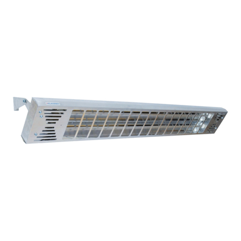
(a) Sun-Zone is designed for operation at 240V 50Hz.
(b) Mains supply cable should be 3 core heat resistant PVC/PVC to BS 6500 Table 9.
Recommended Cable Sizes
Cat No Rating Cable Size (Metric)
HE6502 2 kW 32/.20
HE6503 3 kW 30/.25
(c) A double pole isolating switch should be used in every Sun-Zone installation.
(d) Remove the terminal cover. Pass the mains cable through the cable clamp fitted. Tighten securely.
(e) Strip outer cable insulation and cover the line (Brown) and neutral (Blue) conductors with the sleeving provided. The
brown insulated conductor to the terminal marked ‘L’, the blue insulated conductor to the terminal marked ‘N’, and the
yellow/green conductor connected to the earth stud marked adjacent to the terminal block. A good earth connection
MUST always be made to the heater before it is switched on.
(f) The heater must be installed and tested in accordance with the latest edition of the IEE regulations for the Electrical
Equipment of Buildings.
(g) As a protection against a decrease in earth leakage resistance of the sheathed wire element it is recommended that for
complete safety a sensitive current operated residual current circuit breaker is always included in a Sun-Zone circuit.
Special Note
Sun-Zone uses metal sheathed wire elements and it is a characteristic of such elements that a small amount of moisture can be
absorbed from the atmosphere during storage, or even after installation if not in regular use. It is possible that the amount of
moisture absorbed could decrease the earth leakage resistance with spurious operation of the current sensitive earth leakage
circuit breaker recommended for a Sun-Zone circuit. Should such a condition occur, disconnect the heater from the circuit and
run it for a few minutes in the circuit without the earth leakage protection. This will drive off any offending moisture. Return the
circuit to its correct state with the RCCB connected. This procedure must only be carried out by a competent electrician.
4. MAINTENANCE
ALWAYS ENSURE THAT THE MAINS ELECTRICAL SUPPLY IS SWITCHED OFF BEFORE ANY OPERATION IS CARRIED
OUT ON THE HEATER.
To maintain the efficiency of the reflector clean it occasionally with a damp cloth ensuring all moisture is removed before
switching on. Do not use any abrasive polishes.
Element Replacement
(a) ENSURE MAINS SUPPLY IS SWITCHED OFF.
(b) Remove the terminal cover and disconnect the element leads from the terminal block.
(c) Slide off the wire-guard.
(d) Remove the screw holding the element support nearest to the terminal block.
(e) Straighten the support clips at the back of the reflector and push out the failed element.
(f) Fit a new element and reassemble in reverse order (e – a)
5. SPARES
HE6522 240V 2 kW element for HE6502
HE6523 240V 3 kW element for HE6503
HE6524 pair of mounting brackets
In the interest of progress the Company reserves the right to vary
specification from time without notice. The material listed is offered
subject to the Company’s General Conditions of Sales, a copy of which
may be obtained on request.
WARNING
IF THIS HEATER IS FITTED IN A BATHROOM IT MUST BE MOUNTED IN SUCH A POSITION THAT NO PART CAN BE
TOUCHED BY A PERSON USING A BATH, SHOWER OR WASHBASIN AND IN SUCH A SITUAATION IT MUST BE
INSTALLED IN ACCORDANCE WITH THE LATEST EDITION OF IEE WIRING REGULATIONS FOR BUILDINGS. THE
GUARD ON THIS APPLIANCE CONFORMS TO THE REQUIREMENTS OF BS 1945 1971 AND SATISFIES THE HEATING
APPLIANCE (FIREGUARDS) REGULATIONS 1973. THE GUARD IS TO PREVENT RISK OF FIRE OR INJURY FROM
BURNS, AND NO PART OF IT SHOULD BE PERMANENTLY REMOVED. IT DOES NOT GIVE FULL PROTECTION FOR
YOUNG CHILDREN OR THE INFIRM.
