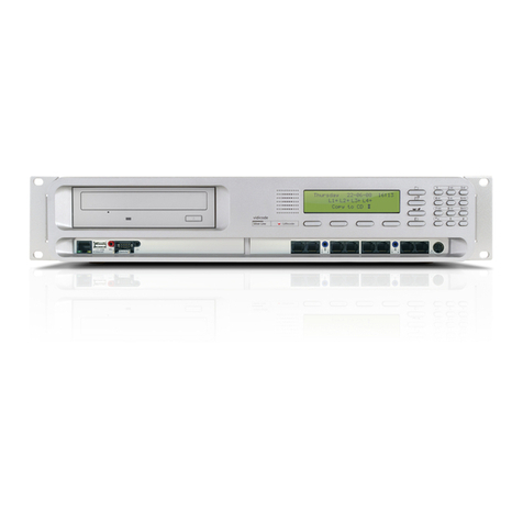
Clavister NetWall 6000 Series User manual

Clavister NetWall 6000 Series
Getting Started Guide

Clavister NetWall 6000 Series
Getting Started Guide
Published 2021-10-26
Copyright © Clavister AB
Sjögatan 6J
SE-89160 Örnsköldsvik
SWEDEN
Head office/Sales: +46-(0)660-299200
Customer support: +46-(0)660-297755
www.clavister.com
Copyright Notice
This publication, including all photographs, illustrations and software, is protected under
international copyright laws, with all rights reserved. Neither this manual, nor any of the material
contained herein, may be reproduced without written consent of Clavister.
Disclaimer
The information in this document is subject to change without notice. Clavister makes no
representations or warranties with respect to the contents hereof and specifically disclaims any
implied warranties of merchantability or fitness for a particular purpose. Clavister reserves the
right to revise this publication and to make changes from time to time in the content hereof
without any obligation to notify any person or parties of such revision or changes.
Limitations of Liability
UNDER NO CIRCUMSTANCES SHALL CLAVISTER OR ITS SUPPLIERS BE LIABLE FOR DAMAGES OF
ANY CHARACTER (E.G. DAMAGES FOR LOSS OF PROFIT, SOFTWARE RESTORATION, WORK
STOPPAGE, LOSS OF SAVED DATA OR ANY OTHER COMMERCIAL DAMAGES OR LOSSES)
RESULTING FROM THE APPLICATION OR IMPROPER USE OF THE CLAVISTER PRODUCT OR
FAILURE OF THE PRODUCT, EVEN IF CLAVISTER IS INFORMED OF THE POSSIBILITY OF SUCH
DAMAGES. FURTHERMORE, CLAVISTER WILL NOT BE LIABLE FOR THIRD-PARTY CLAIMS AGAINST
CUSTOMER FOR LOSSES OR DAMAGES. CLAVISTER WILL IN NO EVENT BE LIABLE FOR ANY
DAMAGES IN EXCESS OF THE AMOUNT CLAVISTER RECEIVED FROM THE END-USER FOR THE
PRODUCT.
2

Table of Contents
Preface ................................................................................................................ 5
1. NetWall6000Series Overview ............................................................................. 7
1.1.Unpacking ............................................................................................. 7
1.2.Interfacesand Ports ................................................................................10
1.3.ZeroTouchSupport ...............................................................................12
1.4.Hardware SensorMonitoring ...................................................................14
2. Registering with Clavister ..................................................................................16
3. Installation ......................................................................................................21
3.1.GeneralInstallation Guidelines .................................................................21
3.2.Flat Surface Installation ...........................................................................23
3.3.RackInstallation .....................................................................................24
3.3.1.FrontBracket Installation ..............................................................24
3.3.2.Side-RailInstallation .....................................................................25
3.4.ManagementComputer Connection .........................................................26
3.5.RJ45Console PortConnection ..................................................................29
3.6.Micro-USBConsolePort Connection .........................................................31
3.7. Connecting Power ..................................................................................33
4. cOS Core Configuration .....................................................................................38
4.1.Web Interface andWizard Setup ...............................................................38
4.2.ManualWeb Interface Setup ....................................................................48
4.3.ManualCLI Setup ...................................................................................63
4.4.LicenseInstallation .................................................................................71
4.5.SetupTroubleshooting ...........................................................................74
4.6.NextStepswithcOSCore ........................................................................76
5. PSU Replacement .............................................................................................79
6. Interface ExpansionModules ..............................................................................82
7. Power overEthernet Setup ................................................................................87
8. ResettingtoFactoryDefaults ..............................................................................90
9. Warranty Service ..............................................................................................93
10.Safety Precautions ..........................................................................................95
A. NetWall6000Series Specifications ......................................................................98
3

List of Figures
1.1.AnUnpackedNetWall6000Series Unit ............................................................... 7
1.2.NetWall6000 SeriesInterfacesand Ports ............................................................10
3.1. NetWall 6000 Series Side-rail Kit (One Side Only) ................................................. 25
3.2.NetWall6000 Series Side-railAttachment ...........................................................25
3.3.ANetWall6000 SeriesSide-rail in Position ..........................................................25
3.4. NetWall 6000 Series RJ45 Local Console Port Connection ..................................... 29
3.5. The NetWall 6000 Series Micro-USB Local Console Port ........................................ 31
3.6.RearViewofaNetWall6000Series Unit .............................................................33
3.7.NetWall6000 SeriesPower Inlet .......................................................................33
3.8. NetWall 6000 Series Connected Plug with Retaining Bracket ................................. 34
3.9. NetWall 6000 Series Second PSU Insertion ..........................................................34
3.10. ANetWall6000 SeriesPSU (DCPower) .............................................................35
5.1.ANetWall6000 SeriesPSU (ACPower) ...............................................................79
5.2.NetWall6000 SeriesPSU AlarmShutoffButton ...................................................80
5.3.NetWall6000 SeriesPSU PowerLED ..................................................................80
5.4.NetWall6000 SeriesPSU Removal .....................................................................81
6.1. NetWall 6000 Series 8 x RJ45 Gigabit Expansion Module ....................................... 82
6.2. NetWall 6000 Series 8 x SFP Gigabit Interface Module .......................................... 83
6.3. NetWall 6000 Series 4 x SFP+ 10 Gigabit Expansion Module .................................. 83
6.4. NetWall 6000 Series 4 x SFP+ 10 Gigabit Expansion Module with QAT .................... 83
6.5. NetWall 6000 Series 2 x QSFP 40 Gigabit Expansion Module .................................. 84
6.6. NetWall 6000 Series Expansion Module Installation (Slot 1) ................................... 84
6.7.Insertion of an Ethernet Module .......................................................................86
7.1. NetWall 6000 Series 8 x RJ45 Gigabit with PoE/PoE+ Expansion Module .................. 87
7.2.NetWall6000 SeriesPoE PowerSupply ..............................................................88
7.3. NetWall 6000 Series PoE Power Supply Connection ............................................. 88
8.1.Factory Reset Using theWeb Interface ...............................................................91
4

Preface
Target Audience
The target audience for this guide is the administrator who has taken delivery of a packaged
Clavister NetWall 6000 Series appliance and is setting it up for the first time. The guide takes the
user from unpacking and installation of the device through to power-up, including network
connections and initial cOS Core configuration.
Text Structure
The text is divided into chapters and subsections. Numbered subsections are shown in the table
of contents at the beginning of the document.
Notes to the main text
Special sections of text which the reader should pay special attention to are indicated by icons
on the left hand side of the page followed by a short paragraph in italicized text. There are the
following types of such sections:
Note
This indicates some piece of information that is an addition to the preceding text. It may
concern something that is being emphasized or something that is not obvious or
explicitly stated in the preceding text.
Tip
This indicates a piece of non-critical information that is useful to know in certain
situations but is not essential reading.
Caution
This indicates where the reader should be careful with their actions as an undesirable
situation may result if care is not exercised.
Important
This is an essential point that the reader should read and understand.
Warning
This is essential reading for the user as they should be aware that a serious situation
may result if certain actions are taken or not taken.
5

Text links
Where a "See section" link is provided in the main text, this can be clicked on to take the reader
directly to that reference. For example, see Appendix A, NetWall 6000 Series Specifications.
Web links
Web links included in the document are clickable. For example, http://www.clavister.com.
Trademarks
Certain names in this publication are the trademarks of their respective owners.
cOS Core is the trademark of Clavister AB.
Windows,Windows XP,Windows Vista,Windows 7,Windows 8 and Windows 10 are either
registered trademarks or trademarks of Microsoft Corporation in the United States and/or other
countries.
Apple,Mac and Mac OS are trademarks of Apple Inc. registered in the United States and/or other
countries.
Preface
6

Chapter 1: NetWall 6000 Series Overview
• Unpacking, page 7
• Interfaces and Ports, page 10
• Zero Touch Support, page 12
• Hardware Sensor Monitoring, page 14
Important: Only cOS Core version 14.00.00 or later is supported
The NetWall 6000 Series hardware product can run any cOS Core version from 14.00.00
onwards. Earlier versions are not supported and a downgrade should not be attempted.
1.1. Unpacking
Figure 1.1. An Unpacked NetWall 6000 Series Unit
This section details the unpacking of a single NetWall 6000 Series device. Open the packaging
box used for shipping and carefully unpack the contents. The packaging should contain the
following:
• The NetWall 6000 Series appliance.
• Local console cable.
7

• Power cable for the single PSU supplied in the base unit.
• A rack mount kit for a 19-inch rack.
Note that the NetWall 6000 Series comes with only a single power supply unit (PSU) installed as
standard. This can be for AC (the default) or DC power. A second PSU for redundancy can be
ordered separately from your Clavister sales office and fitted on-site into the unused PSU slot on
the back of the unit. This topic is discussed further in Chapter 5, PSU Replacement. Note that the
fans in the NetWall 6000 Series are not field replaceable.
Note: Report any items that are missing
If any items are missing from the NetWall 6000 Series package, please contact your sales
representative.
Support Agreements
All purchasers of a new NetWall hardware product must also subscribe to one of the available
cOS Core support agreements. These provide access to cOS Core updates and provide a
hardware replacement service in the event of a hardware fault. The terms of warranty are
described further in Chapter 9, Warranty Service, along with a description of the hardware
replacement procedure.
The Cold Standby Service
To ensure maximum uptime, a Cold Standby (CSB) Service is available from Clavister as an addition
to certain cOS Core support agreements. This service allows a second, identical NetWall 6000
Series unit to be purchased at a discount so that it can quickly substitute for the original unit in
case of failure, with the ability to quickly reassign the original cOS Core license to the standby
unit. When the faulty unit is returned to Clavister, a new cold standby unit is immediately sent
back. More details about the CSB service can be found in the separate NetWall Hardware
Replacement Guide PDF publication.
Downloading NetWall 6000 Series Resources
All documentation, version upgrades and other resources for the NetWall 6000 Series can be
downloaded from the Clavister website after logging into the relevant MyClavister account.
Contacting Clavister Product Support
Clavister customer support can be contacted by logging in as a customer and reporting an issue
on the company website at https://www.clavister.com. Alternatively, the direct support telephone
number is +46 (0)660-29 77 55 (answered 24/7). Sales enquiries should be directed to the head
office number +46 (0)660-29 92 00 during business hours.
End of Life Treatment
The NetWall 6000 Series appliance is marked with the European Waste Electrical and Electronic
Equipment (WEEE) directive symbol which is shown below.
Chapter 1: NetWall 6000 Series Overview
8

The product, and any of its parts, should not be discarded using a regular refuse disposal
method. At end-of-life, the product and parts should be given to an appropriate service that
deals with the disposal of such specialist materials.
WARNING: REPLACE ANY INTERNAL BATTERIES CORRECTLY
THERE IS A RISK OF EXPLOSION IF AN INTERNAL BATTERY IS REPLACED WITH THE
INCORRECT TYPE. DISPOSE OF ANY USED INTERNAL BATTERIES APPROPRIATELY.
Chapter 1: NetWall 6000 Series Overview
9

1.2. Interfaces and Ports
This section is an overview of the NetWall 6000 Series product's external connectivity options.
Figure 1.2. NetWall 6000 Series Interfaces and Ports
The NetWall 6000 Series features the following connection ports on the front panel:
•An RJ45 RS-232 local console port
This port can used for direct access to the cOS Core Boot Menu and the cOS Core Command
Line Interface (CLI). Connecting to this port is described in Section 3.5, “RJ45 Console Port
Connection”.
•A micro-USB (type micro-B) local console port
This port provides an alternative means for a local console connection and is marked with the
letter C. Like the RJ45 console port, this is used for direct access to the cOS Core Boot Menu
and the cOS Core Command Line Interface (CLI). Connection to this port is discussed in
Section 3.6, “Micro-USB Console Port Connection”.
If local console connections are made to the RJ45 and micro-USB ports at the same time, the
micro-USB port will automatically take precedence.
•8 x RJ45 Gigabit Ethernet interface ports
These ports have sequential logical cOS Core interface names from G1 to G8. They all support
10BaseT, 100BaseTx and 1000BaseT.
The G1 interface is the default interface for management access over a network. However, it
can also be used for other purposes. The G8 interface has a DHCP client enabled on it in the
default cOS Core configuration so it can be automatically assigned an IP address by an ISP.
•2 x 10 Gigabit SFP+ Ethernet interfaces
These ports have the logical cOS Core interface names X1 and X2. They both support 10
Gigabit Enhanced Small Form-factor Pluggable (SFP+) modules.
•2 x Ethernet interface expansion slots
These slots are on the right side of the front panel and, in a new unit, are covered with a
removable panel since they will be empty. Expansion modules can be ordered separately for
these slots and the following module options are available:
i. 8 x RJ45 Gigabit Ethernet interfaces.
ii. 8 x RJ45 Gigabit Ethernet interfaces with Power over Ethernet (PoE).
This must be installed in the second slot only (on the far right-hand side).
iii. 8 x SFP Gigabit interfaces. Note that this module cannot be used in the first slot E1 which
is nearest the fixed interfaces.
iv. 4 x SFP+ 10 Gigabit interfaces.
Chapter 1: NetWall 6000 Series Overview
10

v. 4 x SFP+ 10 Gigabit interfaces with QAT.
The QAT feature will be automatically used by cOS Core for IPsec acceleration.
vi. 2 x QSFP 40 Gigabit interfaces.
Module installation is discussed further in Chapter 6, Interface Expansion Modules as well as
details about logical name assignment in cOS Core.
Note: The two USB Type A ports are not currently used
The two USB Type A ports on the 6000 Series front panel are for future functionality and
are not currently used by cOS Core.
The full connection capabilities of all the NetWall 6000 Series Ethernet interfaces are listed at the
end of Appendix A, NetWall 6000 Series Specifications.
Connecting to the Internet and Using InControl Zero touch
Any Ethernet interface could be used for Internet connection but the G8 interface has a DHCP
client enabled in the default cOS Core configuration. This means it can automatically receive a
DHCP lease from an ISP if used for connection to the Internet. However, note that this interface
must be used for Internet connection when the unit is automatically managed on initial startup
by InControl using its Zero Touch feature. This is discussed further in Section 1.3, “Zero Touch
Support”.
RJ45 Ethernet Interface Status LEDs
The status lights on the sides of the NetWall 6000 Series RJ45 Ethernet interface sockets indicate
the following states for each interface:
•Left LED:
i. Solid Green - The interface has power.
ii. Flashing Green - The interface is active.
•Right LED:
i. Dark - 10 Mbit link or no link.
ii. Green - 100 Mbit link.
iii. Yellow - 1000 Mbit link.
Display and Keypad
The NetWall 6000 Series features a display and keypad on the front panel. This is not used by the
current version of cOS Core and is intended for use by future versions.
Chapter 1: NetWall 6000 Series Overview
11

1.3. Zero Touch Support
The NetWall 6000 Series product is able to support the Zero Touch feature in the Clavister
InControl management software product. This means that it is possible to power up a brand new
NetWall 6000 Series, connect it to the Internet, and the NetWall 6000 Series device will
automatically register itself with an InControl server. The device can then be remotely brought
under centralized InControl management and configured remotely, without any local
configuration needing to be done.
However, this feature will only work if the following prerequisites are true:
• The version of InControl being used for device management is 2.00.00 or later.
• The FQDN or IP address of the management InControl server has been set in the MyClavister
account associated with the NetWall 6000 Series device. This is done by logging in to the
relevant MyClavister account, selecting Settings and then selecting the Zero Touch tab. Only
one InControl server address can be associated with one MyClavister account.
• The zero touch feature has been enabled for the license associated with the NetWall 6000
Series device. This in the MyClavister account by selecting Licenses and then enabling the Zero
Touch button next to the relevant license. If the zero touch button is grayed out then the
feature is not available with that device. There is an option in the previous step to always
enable zero touch by default for all new licenses.
• The version of cOS Core running on the NetWall 6000 Series must be 12.00.16 or later. This
might require an upgrade of the factory installed cOS Core version.
• The cOS Core configuration is in its "factory default" state. Following an upgrade to a version
that supports zero touch or any configuration change, this will require a manual reset to the
default cOS Core configuration. In the Web Interface this is done by going to:
Status > Maintenance > Reset & Restart
And then selecting the following option:
Reset the configuration to current core default
Note that a full hardware reset to factory defaults will undo any cOS Core version upgrade
and this should therefore not be done. Also note that any configuration change that is saved
after a reset to the default configuration will disable the zero touch feature.
• The NetWall 6000 Series can be connected to an ISP or other network that can provide
Internet access and that has a DHCP server enabled which can provide a public DNS server
address to the device. Note that physical connection to the Internet should be performed
only after the device is running a zero touch supporting version of cOS Core with the factory
default configuration.
• Access is not blocked by surrounding network equipment for TCP traffic on port 998. This
traffic is required for the NetWall 6000 Series to communicate with the InControl server. DNS
traffic between the NetWall 6000 Series and public DNS servers must also not be blocked.
Internet Connection Must Use a Specific Interface for Zero Touch
When the NetWall 6000 Series is running a version of cOS Core that supports the zero touch
feature, the initial connection to the Internet for InControl management must be made via the
G8 interface for the feature to function.
Chapter 1: NetWall 6000 Series Overview
12

Zero Touch Can Also Simplify Hardware Replacement
In addition to simplifying the addition of a new NetWall 6000 Series, the zero touch feature can
also simplify hardware replacement of a NetWall 6000 Series with another NetWall 6000 Series.
When the replacement hardware is connected to the Internet, InControl can automatically install
the correct license as well as the correct cOS Core version. In addition, InControl will upload its
copy of the cOS Core configuration from the old hardware.
A complete description of the zero touch feature and how it functions can be found in the
separate InControl Administration Guide in the chapter titled Zero Touch.
Chapter 1: NetWall 6000 Series Overview
13

1.4. Hardware Sensor Monitoring
The NetWall 6000 Series is equipped with sensors that provide cOS Core with information about
operational parameters such as CPU temperature. This information is available to the
administrator through the cOS Core management interfaces.
In addition, log message alerts can be automatically generated if a sensor reaches a value outside
of its normal operational range.
Configuring this feature, as well as a list of all the sensors available on each Clavister hardware
model and their normal ranges, can be found in the Hardware Monitoring section of the separate
cOS Core Administration Guide.
Chapter 1: NetWall 6000 Series Overview
14

Chapter 1: NetWall 6000 Series Overview
15

Chapter 2: Registering with Clavister
Before applying power to the NetWall 6000 Series and starting cOS Core, it is important to
understand the customer and product registration procedures. There are two types of
registration:
•Registering as a Clavister Customer
This involves registering basic contact and company information on the Clavister website
and establishing login credentials. Later, these credentials can also be used by cOS Core for
automatically registering the 6000 Series hardware unit and automatically downloading the
correct license.
This is a mandatory requirement for all new customers and needs to be done only once. A
description of doing this can be found below. Even if registration is not done before starting
the cOS Core wizard, the wizard will provide a link to the registration page so it can be done
while the wizard is running.
•Registration of a NetWall 6000 Series Hardware Unit
This is mandatory for every hardware unit before a license can be downloaded. It can be
done in the following ways:
i. Automatic registration after cOS Core starts - This can done by the Setup Wizard
which starts automatically in the Web Interface when cOS Core is started for the first
time. The wizard is described in Section 4.1, “Web Interface and Wizard Setup”.
ii. Manual registration of the NetWall 6000 Series on the Clavister website - This is
described in the last half of this chapter. Manual registration may be necessary if the
appliance does not have Internet access.
A. Registering as a Clavister Customer
The NetWall 6000 Series registration steps for a first time user of Clavister hardware are as
follows:
1. Open a web browser, go to https://www.clavister.com and select the MyClavister link.
16

2. The MyClavister login page is presented. If you are already registered, log in and skip to step
8. If you are a new customer accessing MyClavister for the first time, click the Create
Account link.
3. The registration page is now presented. The required information should be filled in. In the
example below, a user called John Smith is registering.
4. When the registration details are accepted, an email is sent to the email address given so
that the registration can be confirmed.
Chapter 2: Registering with Clavister
17

5. Below is an example of the heading in the email that would be received.
6. The confirmation link in the email leads back to the Clavister website to show that
confirmation has been successful and logging in is now possible.
7. After logging in, the customer name is displayed with menu options for changing settings
and logging out. Note also that multi-factor authentication can be enabled for increased
security in Settings.
Chapter 2: Registering with Clavister
18

B. Registration of the NetWall 6000 Series
This section can be skipped if the NetWall 6000 Series unit has access to the Internet. With
Internet access available, registration can be performed automatically by the cOS Core Setup
Wizard which will appear as a browser popup window in the Web Interface when cOS Core starts
for the first time. The wizard is described in Section 4.1, “Web Interface and Wizard Setup”.
If the unit does not have Internet access then manual registration is required and this is done
using the following steps:
8. Now, log into the MyClavister website and select the Register License menu option.
9. Select the NetWall option.
10. The registration fields will be displayed. After selecting the product type, enter the Hardware
Serial Number and Service Tag.These two codes are found on a label which should be
attached to the NetWall 6000 Series hardware itself. The label is usually found on the
hardware unit's underside but may be found in another position.
Chapter 2: Registering with Clavister
19

The image below shows an example identification label which illustrates the typical layout of
labels found on Clavister hardware products.
After Successful Hardware Registration
Once the NetWall 6000 Series unit is registered, a cOS Core license for the unit becomes available
for download and installation from Clavister servers. This installation can be done automatically
through the cOS Core Setup Wizard which is described in Section 4.1, “Web Interface and Wizard
Setup”.
If the NetWall 6000 Series is not connected to the Internet, the license must be manually
downloaded from the cOS Core website and then manually uploaded.
All license installation options are listed and discussed in Section 4.4, “License Installation”.
Chapter 2: Registering with Clavister
20
Table of contents
Other Clavister Network Hardware manuals

