2
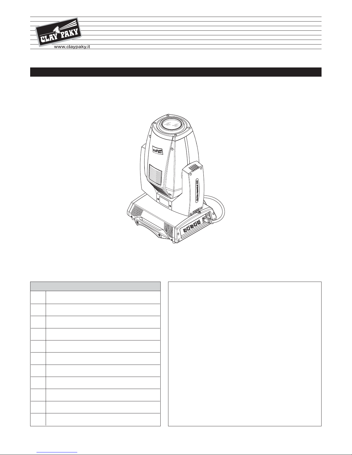
ALPHA PROFILE 700 & “ST ”
• Installation
Make sure all parts for fixing the projector are in a good state of repair.
Make sure the point of anchorage is stable before positioning the projector.
The safety chain must be properly hooked onto the fitting and secured to the framework, so that, if
the primary support system fails, the fitting falls as little as possible.
If the safety chain gets used, it needs to be replaced with a genuine spare.
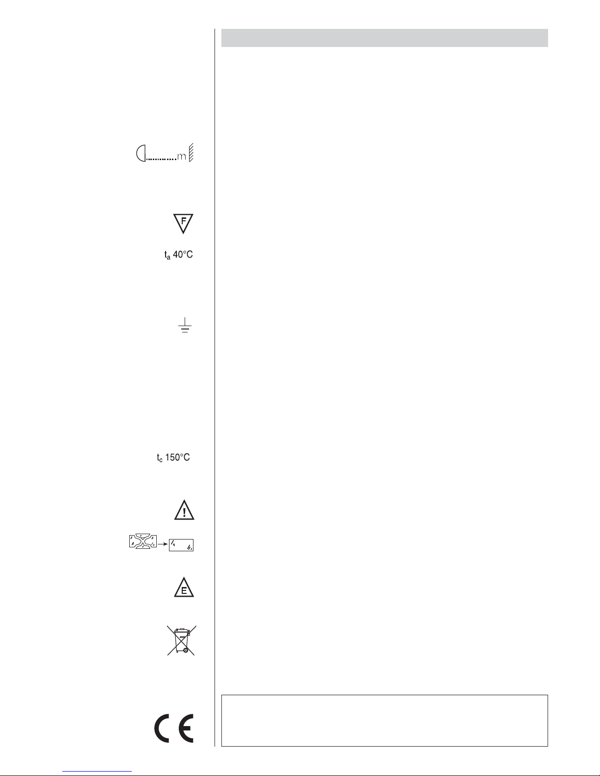
• Minimum distance of illuminated objects
The projector needs to be positioned so that the objects hit by the beam of light are at least 3
metres (9'10'') from the lens of the projector.
• Minimum distance from flammable materials
The projector must be positioned so that any flammable materials are at least 0.20 metres (8") from
every point on the surface of the fitting.
• Mounting surfaces
It is permissible to mount the fitting on normally flammable surfaces.
• Maximum ambient temperature
Do not operate the fixture if the ambient temperature (Ta) exceeds 40° C (104° F).
• IP20 protection rating
The fitting is protected against penetration by solid bodies of over 12mm (0.47”) in diameter (first
digit 2), but not against dripping water, rain, splashes or jets of water (second digit 0).
• Protection against electrical shock
Connection must be made to a power supply system fitted with efficient earthing (Class I appliance
according to standard EN 60598-1).
It is, moreover, recommended to protect the supply lines of the projectors from indirect contact
and/or shorting to earth by using appropriately sized residual current devices.
• Connection to mains supply
Connection to the electricity mains must be carried out by a qualified electrical installer.
Check that the mains frequency and voltage correspond to those for which the projector is designed
as given on the electrical data label.
This label also gives the input power to which you need to refer to evaluate the maximum number
of fittings to connect to the electricity line, in order to avoid overloading.
• Temperature of the external surface
The maximum temperature that can be reached on the external surface of the fitting, in a thermally
steady state, is 150°C (302°F).
• Maintenance
Before starting any maintenance work or cleaning the projector, cut off power from the mains supply.
After switching off, do not remove any parts of the fitting for at least 10 minutes. After this time the
likelihood of the lamp exploding is virtually nill. If it is necessary to replace the lamp, wait for another
20 minutes to avoid getting burnt.
The fitting is designed to hold in any splinters produced by a lamp exploding. The lenses must be
mounted and, if visibly damaged, they have to be replaced with genuine spares.
• Lamp
The fitting mounts a high-pressure lamp that needs an external igniter. This igniter is fitted onto the
apparatus.
- Carefully read the "operating instructions" provided by the lamp manufacturer.
- Immediately replace the lamp if damaged or deformed by heat.
• Battery
This product contains a rechargeable lead-acid or lithium iron tetraphosphate battery. To preserve
the environment, please dispose the battery at the end of its life according to the regulation in force.
SAFETY INFORMATION
The products referred to in this manual conform to the European Community Directives to which
they are subject:
•Low Voltage 2006/95/CE
•Electromagnetic Compatibility 2004/108/CE
3
700W
IP20
LiFePO4
Pb