ENGLISH
STAGE ZOOM 1200
SAFETY INFORMATION
1
INSTALLING THE PROJECTOR
2
INSTRUCTIONS MANUAL
Carefully read this instructions manual in its entirety and keep it safe for future
reference.
It is essential to know the information and comply with the instructions given
in this manual in order to ensure the fitting is installed, used and serviced
correctly and safely.
CLAY PAKY S.p.A. disclaims all liability for damage to the fitting or to other
property or persons deriving from installation, use and maintenance that have
not been carried out in conformity with this instructions manual, which must
always accompany the fitting.
CLAY PAKY S.p.A. reserves the right to modify the characteristics stated in
this instructions manual at any time and without prior notice.
Congratulations on choosing a Clay Paky product! We thank you for your
custom. Please note that this product, as all the others in the rich Clay Paky
range, has been designed and made with total quality to ensure excellent
performance and best meet your expectations and requirements.
HMI 1200 W/S
• Maximum ambient temperature
For the fitting to operate well and reliably, the ambient temperature should not
exceed 35°C (95°F).
• IP20 protection rating
The fitting is protected against penetration by solid bodies with a diameter of over
12 mm (0,47”) (first digit 2), but not against dripping water, rain, splashes or jets of
water (second digit 0).
• Protection against electrical shock
This fitting is classified, in accordance with the type of protection against electrical
shock, in Class I. It must therefore be connected to a power supply system with
efficient earthing.
It is, moreover, recommended to protect the supply lines of the projectors from
indirect contact and/or shorting to earth by using appropriately sized residual current
devices.
• Hooking up to the supply mains
The operations for connecting to the electricity mains must be carried out by a
qualified electrical installer.
Check that the mains frequency and voltage correspond to the frequency and
voltage stated on the electrical data label for which the projector is designed.
This label also gives the input power. Refer to this to evaluate the maximum number
of fittings to connect to the electricity line in order to avoid overloading.
Pay attention to size the neutral conductor of three-phase systems adequately if the
version is used with an electronic power supply unit without p.f. correction since the
neutral current is equal to the sum of the currents on all the active phases. This last
warning does not hold for versions equipped with an electronic power supply unit
with PFC or with an electromagnetic power supply unit.
• Unpacking
Stand the packing on the floor, cut
the straps and open the cardboard
box from the top. Take all the
accessories out of the box and
remove the side structures of the
packing.
Lift the perimeter bands, open the
plastic bag, remove the projector
from the base frame and position it
on a horizontal top where access is
easy to carry out the following
preliminary work.
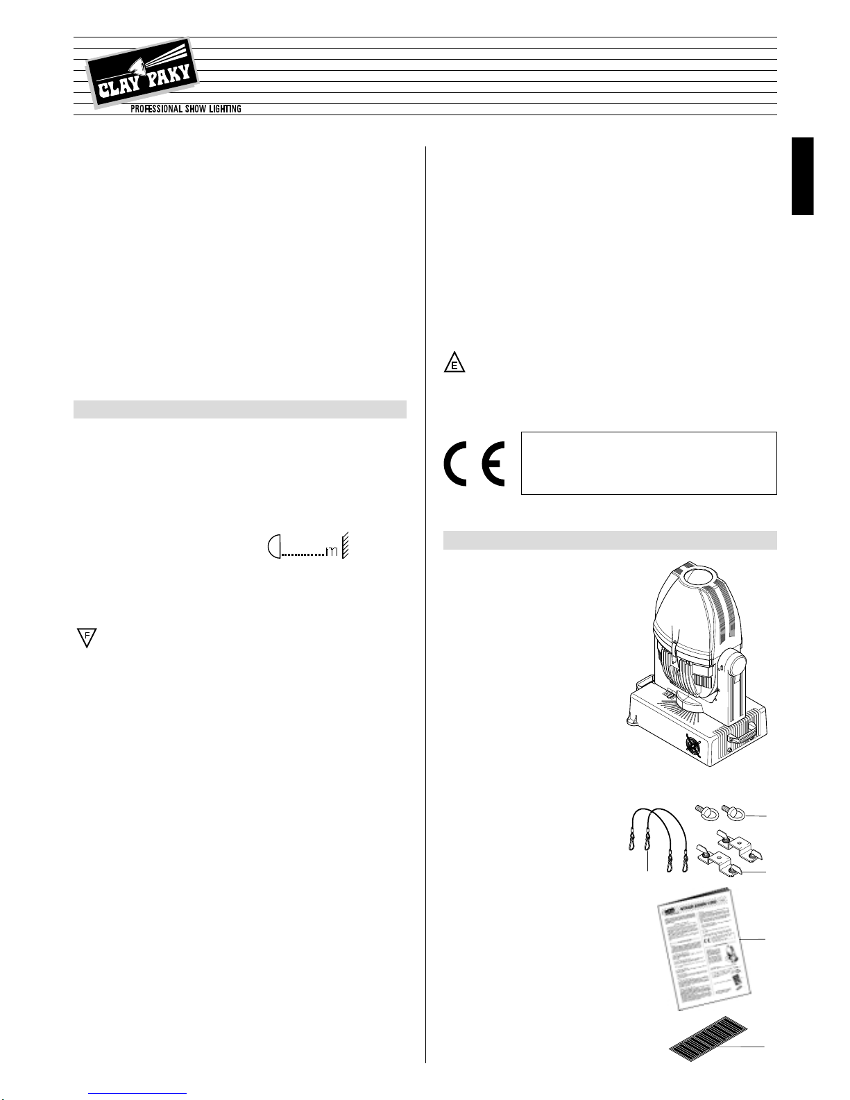
• Packing contents
Besides the projector, the packing also contains the following accessories:
- N. 2 safety ropes code 105041/001 (1)
- N. 2 eyebolts M8x20mm
code 020130/002 (2)
- N. 2 (omega) brackets with fast-lock
code 183102/801 (3)
- This instructions manual code 099550 (4)
- Multilingual label (5) with safety information
code 081968 (located in the projector lampholder
compartment).
• Installation
Make sure all the parts for fixing the projector are in a good state of repair.
Make sure the point of anchorage is stable before positioning the projector.
The safety rope, properly hooked onto the fitting and secured to the framework, must
be installed so that, if the primary support system fails, the fitting falls as little as
possible.If the safety rope gets used, it needs to be replaced with a genuine spare.
• Minimum distance of illuminated objects
The projector needs to be positioned so that
the objects hit by the beam of light are at least
2,5 metres (8’2”) from the lens of the projector.
• Minimum distance of flammable materials
The projector must be positioned so that any flammable materials are at least
0,2 metres (8”) from every point on the surface of the fitting.
It is permissible to mount the fitting on normally flammable surfaces.
• Maintenance
Before starting any maintenance work or cleaning the projector, cut off power from
the supply mains.
After switching off, do not remove any parts of the fitting for 10 minutes. After this
time the likelihood of the lamp exploding is virtually nill. If it is necessary to replace
the lamp, wait for another 15 minutes to avoid getting burnt.
The fitting is designed to hold in any splinters produced by a lamp exploding.
The lenses must be mounted and, if visibly damaged, they have to be replaced with
genuine spares.
• Temperature of the external surface
The maximum temperature that can be reached on the external surface of the fitting,
in a thermally steady state, is 160°C (320°F).
• Lamp
The fitting mounts a high-pressure lamp with an external igniter.
- Carefully read the "operating instructions" provided by the lamp manufacturer.
- Immediately replace the lamp if damaged or deformed by heat.
1
2
3
4
5
ENGLISH
HMI 1200 W/S
(8’2”)
2.5
The products referred to in this manual conform to the
European Community Directives to which they are subject:
• Low Voltage 73/23
• Electromagnetic Compatibility 89/336