Clayton Power LPS User manual

LPS - Van Installation Guide
Lithium Power Supply
V1.2

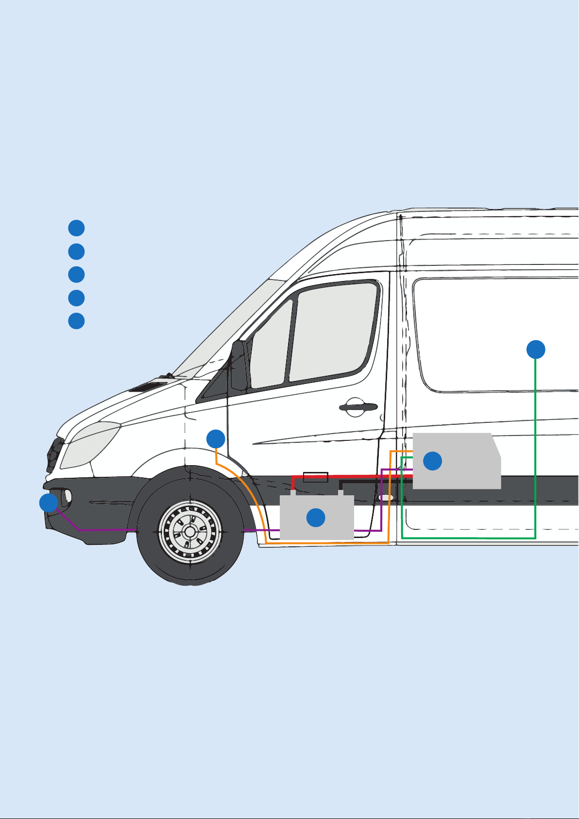
Common setup with main functions:
12 V Output
230 V Output
Charging from the van
Charging from mains
LPS Remote
LPS - Van Installation Guide
2
LPS
1a Unpacking
1b Mounting
Charging from the van
2a Starter battery
2b D+ Ignition signal
Charging from mains
3 Mains connection
Outputs
4a 12 V Output
4b 230 V Output
5 LPS Remote
6 Test
LPS
Van Installation Guide
1
2
3
4
5
1LPS
2Starter Battery
3Ignition Signal
4Mains connection
5LPS Remote
3

LPS - Lithium Power Supply
Unpacking
Anderson SB50 DC Connector
1x Grey: DC IN
1x Red: DC OUT
Neutrik 230 V Connector
1x Blue: 230 V / 50 Hz IN
1x Grey: 230 V / 50 Hz OUT
1x DB9 Communication
4x M3 screws for the
Anderson connectors
4x Anderson SB50 pins
LPS - Lithium Power Supply
4
LPS
1a Unpacking
1b Mounting
Charging from the van
2a Starter battery
2b D+ Ignition signal
Charging from mains
3 Mains connection
Outputs
4a 12 V Output
4b 230 V Output
5 LPS Remote
6 Test
LPS
Van Installation Guide

230 V / 50 Hz OUT
230 V / 50 Hz IN
12 V DC IN
12 V DC OUT
12 V DC fuse
24,4 cm
25 cm
39 cm
230 V / 50 Hz OUT
RCD
COMMUNICATION

LPS Mounting Console (recommended)
Mount the LPS in the van by using an
LPS Mounting Console and 4 screws D4,20.
Part No.: ACWO00107GF
Dimensions: 420 x 300 x 55 mm
Not included the LPS as standard.
PARTS LIST
PART NUMBERQTYITEM
LPS_InsideBracket_004
11
LPS_InsideBracket_Lock
1
2
Hex domed Cap Nut -
M5
23
LOCK WASHER - M52
4
3D Part Name No:
LPS_InsideBracket_Assembly
Date:
02-09-2016
Rev:
.004
Drawn by:
Clayton
Material:
Steel
Sheet:
Scale:
A4 1 : 1
Color coating:
COPYRIGHT:
THIS DRAWING MAY UNDER NO CIRCUMSTANCE BE COPIED OR EDITED
WITHOUT APPROVAL FROM Clayton Power ApS
Pakhusgården 42-48
DK 5000 Odense C
TLF: 46985760
www.claytonpower.com
Drawing No:
LPS-003-600
All Dimensions in mm
Checked by:
ML
187,00
310,00
394,00 251,00
1
2
43
4,20 THRU
LPS - Lithium Power Supply
Mounting
6
LPS
1a Unpacking
1b Mounting
Charging from the van
2a Starter battery
2b D+ Ignition signal
Charging from mains
3 Mains connection
Outputs
4a 12 V Output
4b 230 V Output
5 LPS Remote
6 Test
LPS
Van Installation Guide
Front
Back

7
ATTENTION: Mount the LPS topside up, never upside down or on the side.
ATTENTION: The LPS has forced air cooling. Make sure air can ow freely around the unit.
The LPS has four M5 mounting holes in the bottom.

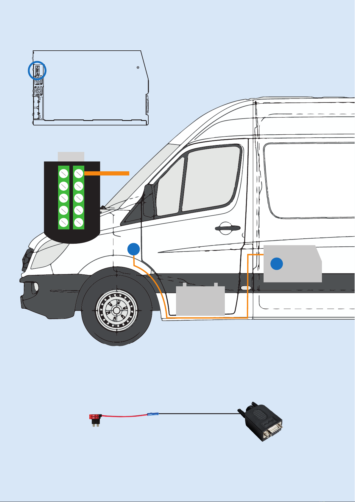
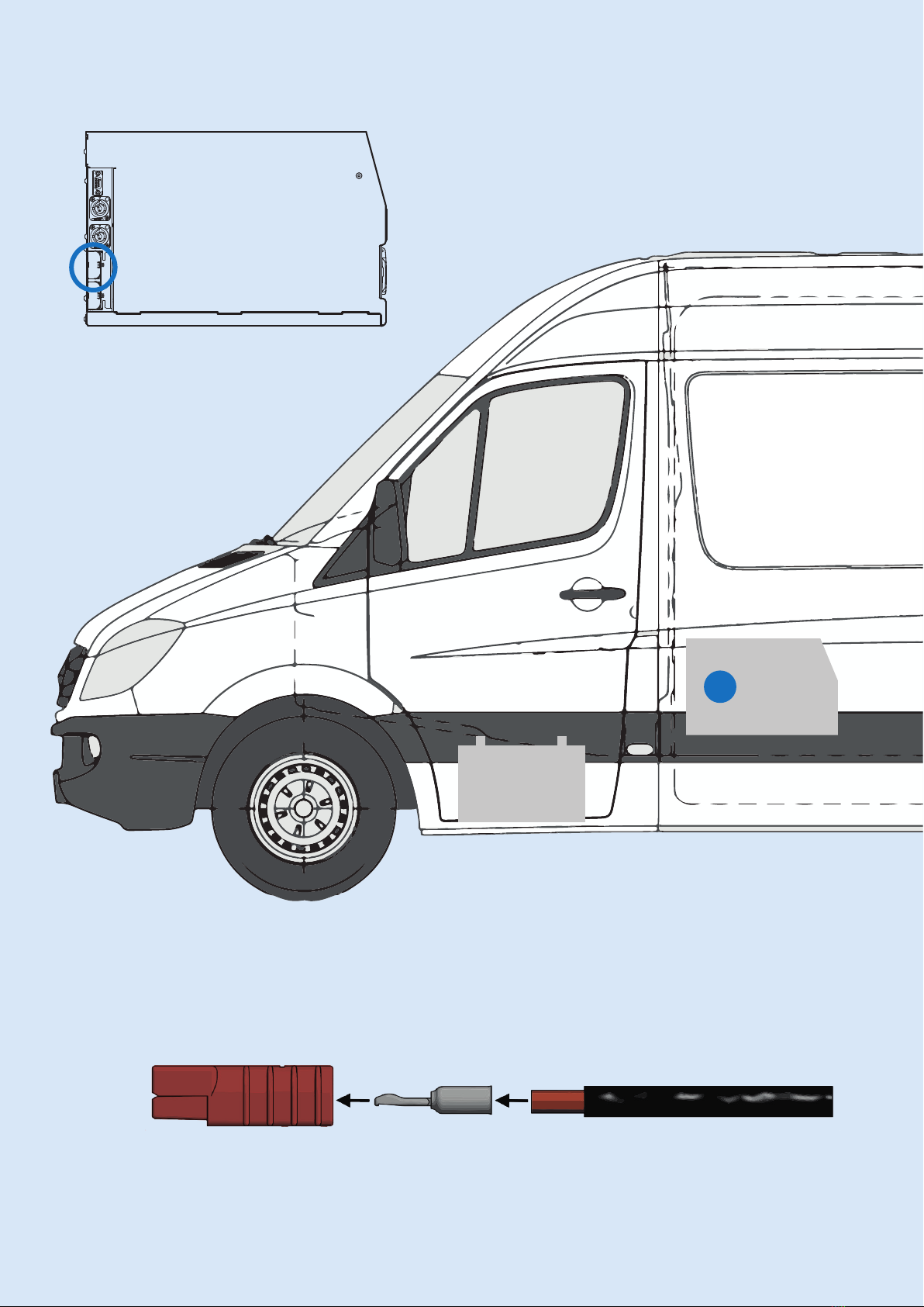
Charging from the van
Starter Battery
LPS (12 VDC IN) Starter Battery
Connect the LPS to plus and minus pole
on the starter battery.
Plus to Plus - including 100A DC fuse
Minus to Minus (direct connection is recommended)
Use 16 mm2 cable. Maximum length: 5m
DC Fuse and Fuse Holder
DC Fuse Holder
Part no.: ACWO 00102GF
DC 100A Fuse
Part no.: ACWO 00103GF
8
LPS
1a Unpacking
1b Mounting
Charging from the van
2a Starter battery
2b D+ Ignition signal
Charging from mains
3 Mains connection
Outputs
4a 12 V Output
4b 230 V Output
5 LPS Remote
6 Test
LPS
Van Installation Guide

9
12 VDC IN
CLICK
IMPORTANT
Always use appropriate
crimping tool
Note: Assembling the power cable correctly is important
as the power load may be high.
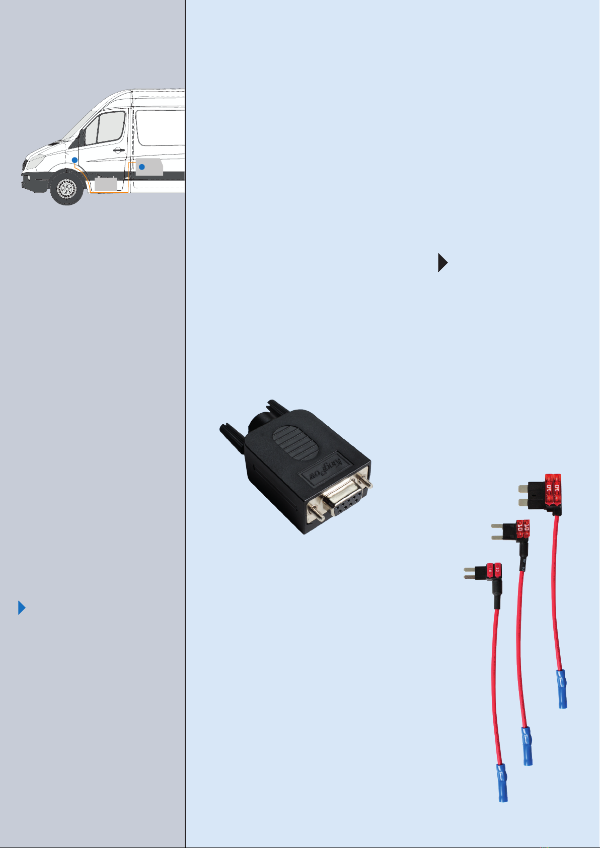
Charging from the van
D+ Ignition signal
LPS (COMMUNICATION - PIN 9) D+ Ignition signal
For automatic charging when the van turns on.
Connect a 0,75 mm2wire to pin 9 in the DB9 connector
to the van’s fuse box with D+ ignition signal.
10
LPS
1a Unpacking
1b Mounting
Charging from the van
2a Starter battery
2b D+ Ignition signal
Charging from mains
3 Mains connection
Outputs
4a 12 V Output
4b 230 V Output
5 LPS Remote
6 Test
LPS
Van Installation Guide
Example:
Fuse Holder with Power Distributor
For easy connection in the van’s fuse box:
Remove the fuse in the van and replace it with
a wire with a double fuse holder.
Connect the wire to the pin 9 in the DB9.
Double fuse holder in 3 versions:
Micro cable + 10A fuse
Mini cable + 10A fuse
Standard cable + 10A fuse
11
9876GND
123 4 5
876GND
876GND
123 4 5
9
COMMUNICATION

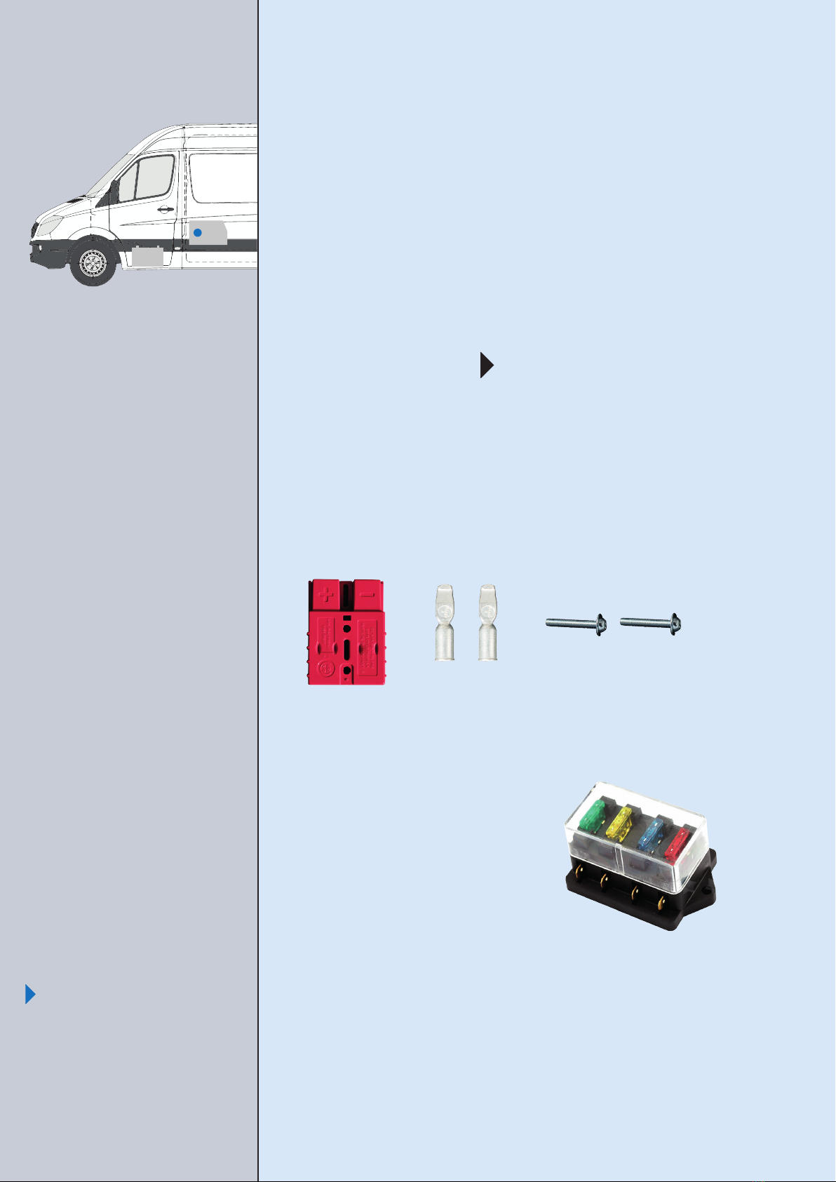
Charging from mains
Mains connection
LPS (230 V IN) Mains connector/plug
Connect the Blue Neutrik with a power cord
to a 230 V plug/connector.
Example:
MiniPlug inlet cable
for mounting in the bumper.
12
LPS
1a Unpacking
1b Mounting
Charging from the van
2a Starter battery
2b Ignition signal
Charging from mains
3 Mains connection
Outputs
4a 12 V Output
4b 230 V Output
5 LPS Remote
6 Test
LPS
Van Installation Guide
Note: If extra charger is installed for the starter battery:
See page 7 in the User Manual.

13
230 V / 50 Hz IN
1.
2.
b
AB
[0 .32"]
8 m m
[0.787”]
20 mm
[0.9”]
PE 23 mm
C
Example:
Wire Ferrules to secure
connection to terminal blocks.
Outputs
12V Output
LPS (12VDC OUT) 12V Appliances
Connect all xed 12 V appliances in
the van via a DC fuse box.
Use 16 mm2 cable. Maximum length 5 m.
Example:
12 V DC fuse box.
Always use a fuse box in case of
break down of an appliance.
14
LPS
1a Unpacking
1b Mounting
Charging from the van
2a Starter battery
2b Ignition signal
Charging from mains
3 Mains connection
Outputs
4a 12 V Output
4b 230 V Output
5 LPS Remote
6 Test
LPS
Van Installation Guide
15
12 VDC OUT
CLICK
IMPORTANT
Always use appropriate
crimping tool
Note: Assembling the power cable correctly is important
as the power load may be high.

Outputs
230 V Output
LPS (230 V OUT) 230V/50Hz Appliances
Connect the Grey Neutrik connector for
the 230 V outlets.
16
LPS
1a Unpacking
1b Mounting
Charging from the van
2a Starter battery
2b Ignition signal
Charging from mains
3 Mains connection
Outputs
4a 12 V Output
4b 230 V Output
5 LPS Remote
6 Test
LPS
Van Installation Guide
Fuses
Both 230 V outputs on the LPS (Schuko on the front, Neutrik in the
back) are protected with 8 A or 10 A relays (depending on model) and
an RCD, which allow you to make xed 230 V installations in the van.
If an installation is wired around the LPS, separate relays must be
used.
General function
When 230 V In is connected the 230 V power will be looped directly
through the unit.

1.
2.
b
AB
[0 .32"]
8 m m
[0.787”]
20 mm
[0.9”]
PE 23 mm
C
17
230 V / 50 Hz OUT
Example:
Wire Ferrules to secure
connection to terminal blocks.

LPS Remote
LPS (COMMUNICATION) LPS Remote
PIN 1: Yellow
PIN 3: Grey/blue
PIN 4: White
PIN 5: Green
Connect the four wires from the LPS Remote
in the DB9 connector.
The brown wire is not in use.
LPS Remote
The LPS Remote is tted with a 6m cable
and a bracket.
The LPS Remote is not included with the
LPS as standard.
Dimensions: 75 x 50 x 15 mm
Part no.: 025-00001GF
18
LPS
1a Unpacking
1b Mounting
Charging from the van
2a Starter battery
2b Ignition signal
Charging from mains
3 Mains connection
Outputs
4a 12 V Output
4b 230 V Output
5 LPS Remote
6 Test
LPS
Van Installation Guide

80°
6,20
6,93
71,49
0,70
3
44
Materiale: 0,7mm fjederstål
Sheet format A4
Mads Lauenborg
1:1
Surface treatment
First angle projection
1/1
Sheet
Rev
Scale
Part No.
Material
Weight
Date
Sign.
Appr.
Created
04.10.2017
04.10.2017
ml
0.02
Material <not specified>
Approved
Title.
01
State
REMOTE BRACKET
A A
B B
C C
D D
6
6
5
5
4
4
3
3
2
2
1
1
Pakhusgaarde 42-48
DK 5000 Odense C
Phone :+45 46985760
COPYRIGHT:
THIS DRAWING MAY UNDER NO CIRCUMSTANCE
BE COPIED OR EDITED WITHOUT APPROVAL FROM
Clayton Power ApS
000226
19
9876GND
1234 5
876GND
876GND
123 4 5
9
LPS Remote Mounting Bracket
COMMUNICATION

Test
LPS
1a Unpacking
1b Mounting
Charging from the van
2a Starter battery
2b Ignition signal
Charging from mains
3 Mains connection
Outputs
4a 12 V Output
4b 230 V Output
5 LPS Remote
6 Test
Push the 12 V LPS Remote button
Check that the LPS starts up and 12 V appliances turn on
Push the 230 V LPS Remote button
Check that the LPS turns on 230 V and test 230 V
appliances
Charging from the van
Turn on the engine - green light is lit
(after less than 10 seconds)
Charging from mains
Connect 230 V to the 230 V input - green light is lit
LPS
Van Installation Guide
20
1 2 3 4
1
2
3
4
Table of contents
Other Clayton Power Power Supply manuals


