Clean Cut ULTRA-LOW User manual

CLEANCUT ULTRA-LOW
INSTALLATION GUIDE
COPYRIGHT © 2020 SAFEWAY SAFETY STEP, LLC
(DBA “CleanCut”) All Rights Reserved
Reproduction or Distribution of this Installation Manual is Strictly Prohibited

**IMPORTANT – PLEASE WATCH INSTALLATION VIDEOS PRIOR TO
READING DIRECTIONS AND BEFORE BEGINNING INSTALLATION**
VIDEO INSTRUCTIONS CAN BE VIEWED AT
WWW.CLEANCUTBATH.COM
IT IS VERY IMPORTANT THAT ALL INSTRUCTIONS IN THE
INSTALLATION MANUAL ARE FOLLOWED THOROUGHLY.
INSTALLATION OF THE CLEANCUT ULTRA-LOW REQUIRES USE OF
POTENTIALLY DANGEROUS TOOLS.
SAFEWAY SAFETY STEP, LLC (DBA “CLEANCUT”) ACCEPTS NO RESPONSIBILITY FOR
ANY TYPE OF INJURY, LOSS OR DAMAGE OCCURRED DURING INSTALLATION OR
SUBSEQUENT USE OF THE CLEANCUT ULTRA-LOW.
FAILURE TO FOLLOW THE INSTRUCTIONS IN THIS INSTALLATION MANUAL SHALL
VOID ANY WARRANTY GIVEN WITH RESPECT TO THE CLEANCUT ULTRA-LOW.
IMPORTANT REMINDER - PLEASE REGISTER THE PRODUCT WARRANTY BY
VISITING WWW.CLEANCUTBATH.COM/WARRANTY. ADDITIONAL CARE & USE
AND WARRANTY INFORMATION IS INCLUDED IN THE KIT.
ADDITIONAL QUESTIONS?
CLEANCUT CUSTOMER SERVICE REPRESENTATIVES ARE AVAILABLE TO ANSWER
QUESTIONS MONDAY-FRIDAY FROM 9AM-4PM EST. FOR QUESTIONS, PLEASE
CALL 877-882-7837 OR VISIT WWW.CLEANCUTBATH.COM.
MSDS SHEET FOR ENCLOSED ADHESIVE AVAILABLE UPON REQUEST.
Page 2of 11

This manual includes an overview of the CleanCut Ultra-Low kit as well as step-by-step
instructions forinstallation.
CleanCut Ultra-Low Installation Kit
The CleanCut Ultra-Low installation kit includes the following items:
•
One CleanCut Ultra-Low
•
One CleanCut Ultra-Low Support Box Structure (large & small box)
•
Template to be used for cutting the tub
•
Two tubes of required adhesive and angled extension nozzle
Tools & Materials
In addition to the items included in the installation kit, the following tools and materials
are recommended to have on hand for installation.
Additional Tools & Materials
Butane Torch
Cardstock Paper
Caulking Gun
Chisels
Deburring Tool (i.e. drywall plane, rasp)
Drain Screens
Drill & Drill Bits
Drop Cloths
Dust Masks
Dustpan & Brush
Ear Protection
Extension Cord
Fire Extinguisher
Gloves
Hammer
Isopropyl Alcohol
Mirror (small)
Paper Towels
Jigsaw with 2” Blade
Masking Tape
Pliers
Pressure Treated 2x4’s
Protective Eye Wear
Reciprocating Saw with Metal Blade
Scissors
Screwdriver
Screws- Assorted Sizes
Sharpie Marker (colored)
Side Grinder with 4.5” Diamond Blade
Utility Knife
Vacuum with Attachment
Wood Shims
Page 3 of 11

Page 4 of 11
Preparing the Tub
1.
Before beginning any work, it is important to inspect the tub for existing chips, markings or other types
of damage. It is always wise to make the owner or manager aware of any existing damage prior to
beginning the installation process.
2.
Prior to beginning the installation, remove any personal items from the bathroom area to create extra
space during the installation and to prevent possible damage or exposure to dust and debris that may
result during the installation process.
3.
One method to minimize the areas where dust can settle is to use a 2-ply drop cloth with the paper
side up to catch and trap dust and other shavings. In particular, a drop cloth should be taped into the
bottom of the tub. This will help to collect debris as well as to help prevent accidentally scratching the
bottom surface of the tub. The drain of the tub should be completely covered to prevent any shaving from
going down into the drain. Make sure that there is no water or dampness in or around the tub.
Due to the significant amount of dust created when cutting a cast-iron tub, it is recommended that all
walls and surfaces are covered, including the floor, before cutting the tub. See other considerations for
cutting cast-iron tubs in the following section.
4.
Confirm that the CleanCut Ultra-Low will fit the bathtub. First, measure the top rail width measurement
as well as the width measurement approximately 14.75” down the tub (bottom measurement)
•The maximum top rail measurement to install the CleanCut Ultra- Low is 6”.
•The maximum bottom measurement to install the CleanCut Ultra- Low is 7.25”.
5.
Using the template that was included in the installation kit, place the template flush against the tub and
begin tracing, use a colored sharpie marker so as to make the lines that are traced easily visible. Flip the
template over and now trace the outside of the tub. Keep in mind that it may not be possible to place the
CleanCut Ultra-Low directly in the center of the tub due to obstructions in the tub area such as the
placement of sinks, vanities or commodes and the use of shower seats may warrant moving the opening
forward as well.
Cutting the Tub
The tub has been marked and is ready to cut.
Safety Considerations
•Safety is of highest importance and it is critical to remember to use the proper safety equipment when
cutting the tub.
•Protective eye and ear wear and filter mask are required.
•Be cognizant of potential safety issues when cutting the tub such as sparks generated during
cutting as well as items that may be located within the tub wall such as water lines, electrical
lines, insulation, etc.

Page 5 of 11
The CleanCut Ultra-Low can be installed in acrylic, fiberglass, steel or cast-iron tubs. On acrylic,
fiberglass or steel tubs, use a side grinder with the diamond blade to make necessary entry points for the
reciprocating saw. For cast-iron tubs, the side grinder with the diamond blade is the only cutting tool
used. If you are cutting a cast-iron tub, please read the special considerations noted below before
beginning to cut.
1.
The first corner notches will be made with the side grinder as illustrated in Figure 1 below.
2.
Using the reciprocating saw on acrylic, fiberglass and steel tubs, cut out the bottom markings
on each side of the tub.
3.
Then cut all four downward cuts. Finish by cutting the two adjoining top pieces.
4.
The opening for the CleanCut Ultra-Low is now completed and you can remove the cut-out section. Use
caution when removing the cut-out section as there may be sharp or jagged edges both on the cut-out
segment and along the edges of where the cuts were made on the sides of the tub. It is helpful to spend
a moment to file down any potential hazard areas. This prevents potential snags with fitting the
CleanCut Ultra-Low and reduces risk of injury.
5.
After the cut-out section of the tub has been removed, take a few moments to clean the area in and
around the tub. Using a dustpan and broom, sweep all dust and shavings. Complete the clean-up by
thoroughly vacuuming the entire area. Wash your hands before you start any work on the Ultra-Low
itself. This will eliminate transferring any dirt or dust to the product.
SPECIAL CONSIDERATIONS FOR CUTTING CAST-IRON TUBS
CleanCut recommends professional installation when installing on cast-iron tubs.
Due to the significant amount of dust created when cutting a cast-iron tub, it is recommended that you
cover all tub and exposed bathroom walls and surfaces (including the floor) with a 2-ply drop cloth to
minimize the amount of dust that can settle. Also, it is recommended that the installer wears protective
coveralls and shoe covers, in addition to protective wear outlined earlier, to minimize the clean-up after
cutting out a cast-iron tub.
Please note that there are several differences when cutting out a cast-iron tub compared to other types of
tubs. The side-grinder with a 4.5” diamond blade is the only tool used when cutting a cast-iron tub. Cast-
iron tubs are a bit more challenging to cut. Vacuum the dust and shavings as you cut the tub.
FIGURE 1
Page 6 of 11
Follow the same pattern when cutting a cast-iron tub as described for the other tub types. Begin by
cutting the bottom lines of your template, followed by the downward vertical cuts, leaving the top
adjoining pieces for last.
Measuring & Cutting the CleanCut Ultra-Low
Once you have completed cutting out the section of the tub, you can begin to fit the CleanCut Ultra-Low
into the tub opening. Please note that the Ultra-Low should be installed with the logo showing on the
outside of the tub.
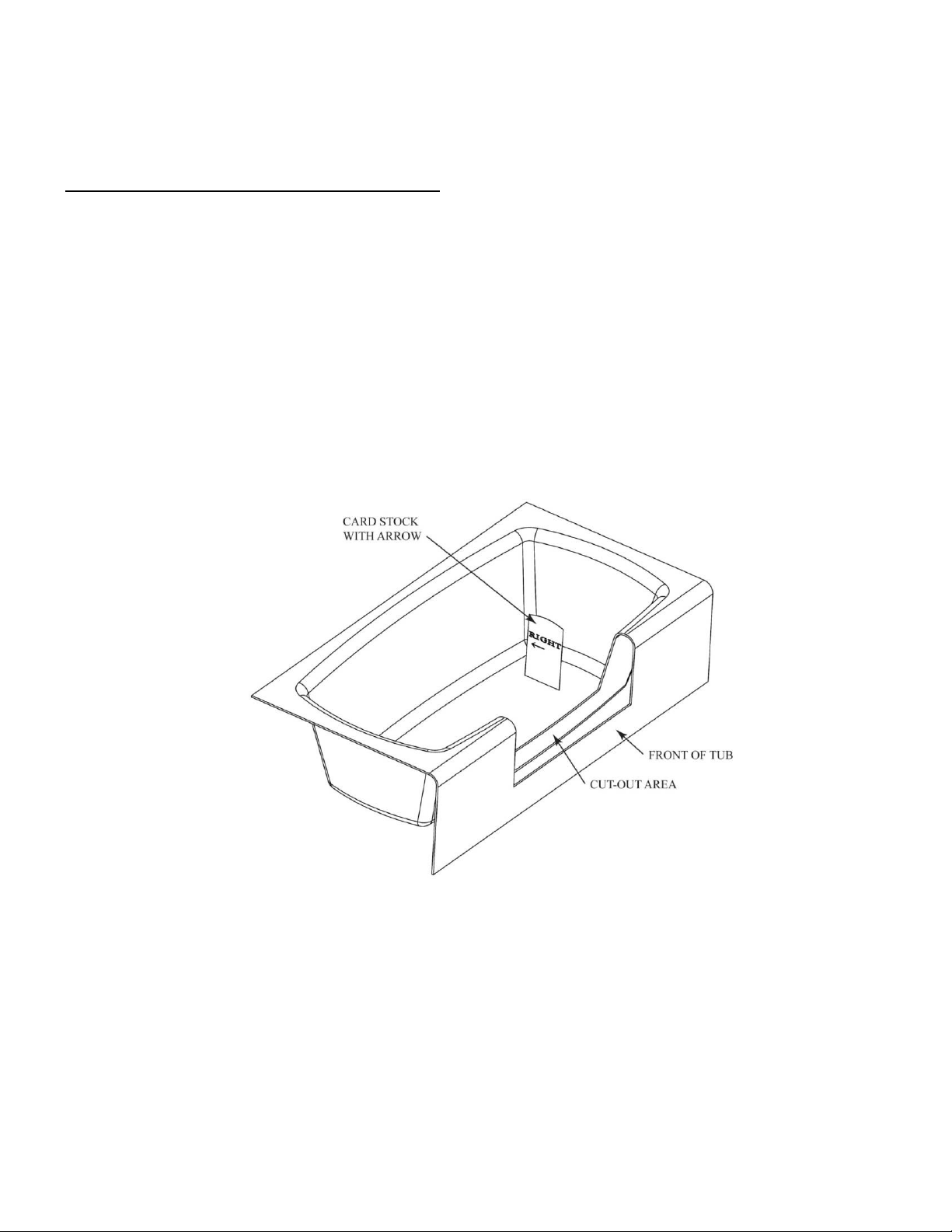
1.
Take a stack of heavy cardstock paper. This is the paper used to trace the cut-out section of the tub
onto the CleanCut Ultra-Low. Place the paper onto the left end and trace the outline of the pattern
onto the paper. Once completed, mark this tracing as “Left”, so as to remember which side was
traced. It is also helpful to place an arrow on the template to indicate which direction is the inside
of the tub.
2.
Repeat the process for the right side of the tub. Mark this tracing “Right”.
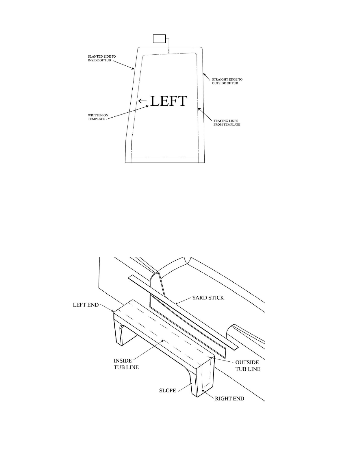
3.
Cut out the paper templates with scissors making sure to keep to the inside of the tracings (Figure
2).
FIGURE 2
4.
It is time to transfer the shape of our cut tub onto the CleanCut Ultra-Low. Before continuing, it is
recommended that a drop cloth approximately 3’ x 4’ size be placed on the floor to prevent any
dust or other debris from transferring onto the CleanCut Ultra-Low.
5.
Place the right end of the CleanCut Ultra-Low on the ground in order to trace the left side of the
CleanCut Ultra-Low. Place the top of the paper template approximately 1” from the top of the
CleanCut Ultra-Low (Figure 3). Place the tracing on the CleanCut Ultra-Low so that the slope is
similar to that of the tub. Trace the outline of the paper onto the CleanCut Ultra-Low with a
continuous line. Continue the lines with a straight edge down and around the corners. Repeat the
same procedure for the right end of the CleanCut Ultra-Low. Remember to place the paper
template approximately 1” down from the top of the CleanCut Ultra-Low before beginning to trace.
Continue the lines with a straight edge down and around the corners.
Page 7 of 11
PATTERN MARKS
- - - - - - - INDICATE
THE AREA TO BE
CUT OUT ON THE
LEFT END OF THE
ULTRA-LOW.
6.
Place the Ultra-Low as shown in Figure 4. Use a tape measure and transfer the shape of the inside
of the tub edge to the Ultra-Low. The inside of the tub may be irregular in shape, so measurements
for the inside line must be made every 3” from one end of the CleanCut Ultra-Low to the other.
Once completed, use your yard stick and marker to connect the markings for the inside line.
Alternate Method: You may use cardstock paper such as done with the sides to create a bottom template.
FIGURE 3
SIDE VIEW OF
LEFT END OF
ULTRA-LOW
1”
FIGURE 4
Page 8 of 11
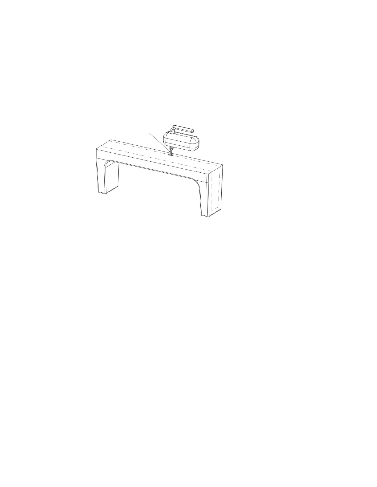
7.
Cut the CleanCut Ultra-Low to fit the cut-out tub opening using a jigsaw (Figure 5). Fasten Velcro-
stripping on both sides of the jigsaw to prevent making any unwanted marks on the CleanCut
Ultra-Low. It is important that a blade less than 2” is used to cut out the CleanCut Ultra-Low so as
to prevent accidentally cutting through the top of the Ultra-Low. Snap off any excess length on the
stock jigsaw blade beyond 2”.
USE THE JIGSAW TO CUT THE LINES TRACED ON THE ULTRA-LOW.
It is required that proper eye protection be worn while using the jigsaw. Cut directly on the center of
the traced lines. Upon reaching the corners while cutting, tilt the jigsaw outward to prevent cutting
past your lines on the vertical ends of the CleanCut Ultra-Low. Remember to tilt your blade on each
corner, cutting all areas that have been marked.
8.
Place the CleanCut Ultra-Low into position. Remember, the face with the CleanCut logo is on the
outside of the tub. Use a small pocket mirror and look for areas on the CleanCut Ultra-Low that
may be catching and prohibiting the CleanCut Ultra-Low from freefalling onto the tub. Use the
jigsaw or drywall plane to trim the CleanCut Ultra-Low where necessary.
9.
Continue this process and repeat as necessary until a desirable close fit is achieved. The
CleanCut Ultra-Low should free fall onto the tub without catching or binding. Once final
adjustments have been made, use a drywall plane or deburring tool (a common potato peeler
works well) to trim the remaining edges.
10.
Having completed use of the jigsaw, take a moment to tidy the tub and work area.
FIGURE 5
Less than 2” blade length
Page 9 of 11
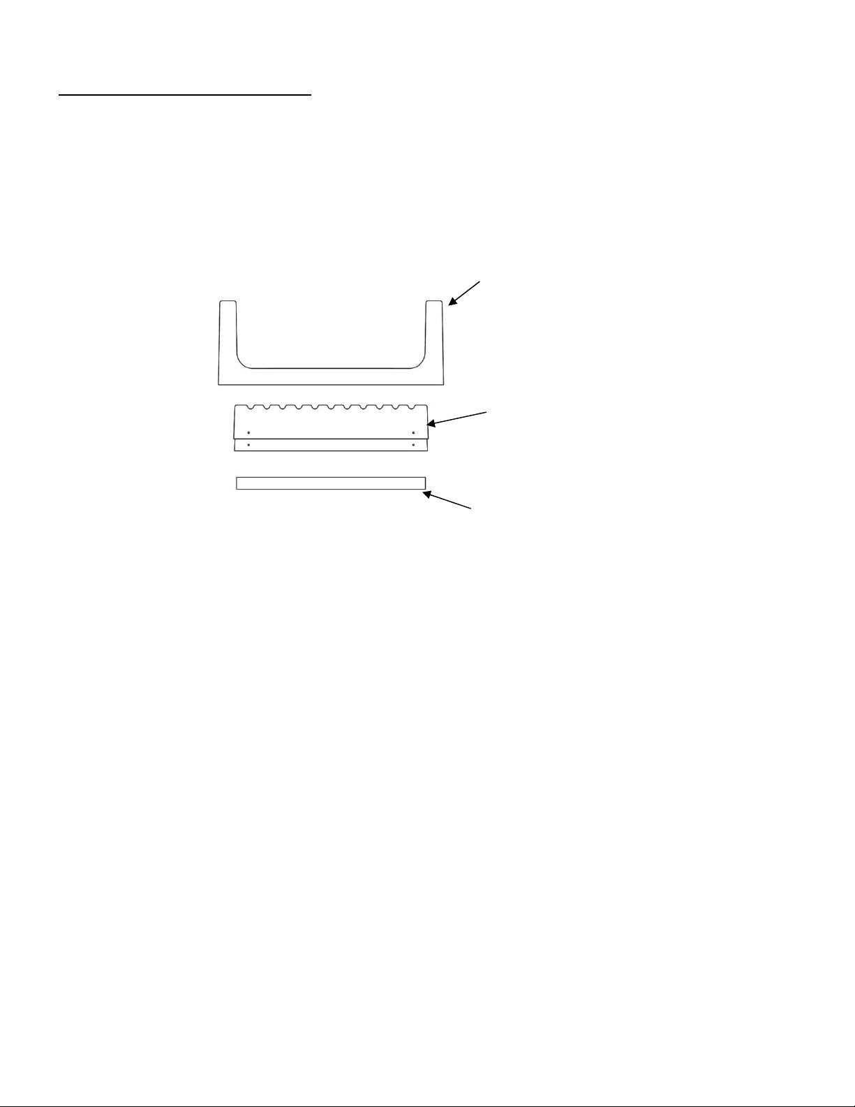
Support Box Structure Installation
Once the CleanCut Ultra-Low has been cut and a satisfactory fit into the tub opening is
achieved, it will be necessary to assemble the support box structure to provide support to the
CleanCut Ultra-Low. An example of the CleanCut Ultra-Low and the support box structure is
illustrated in Figure 6.
The CleanCut Support box structure consists of one small and one large support box. The large
support box will compress over the top of the small box to the necessary height to provide support to
the CleanCut Ultra-Low.
It is important to understand that each tub has variations and modifications may be
necessary in the field. For fiberglass and other types of tubs, it may be necessary to adjust
the installation of the support boxes based on the framing or support material present on
the inside channel of the tub. For example, you may only need to use one of the support
box structures based on the height of the bathtub.
1.
It may be necessary to adjust the support box structure according to the conditions present during
your installation. For example, for wooden sub-floors, begin by screwing or adhering with included
adhesive a treated 2x4 directly to the sub-floor to serve as a base for the support structure. For
concrete floors, a treated 2x4 is adhered directly to the concrete floor with adhesive. The 2x4 might
need to be cut into several sections if there is a support brace in the cut-out channel.
2.
Build the support box structure to appropriate height. If working with a concrete sub-floor,
thoroughly inspect and clean the floor in the tub cut-out channel prior to securing the treated
2x4. Remove any materials from the concrete that may cause an uneven surface. Apply
adhesive directly to the concrete floor. Insert the 2x4s and thoroughly spread the adhesive on
the concrete.
3.
Prior to inserting the small support box, it is first necessary to secure a 22 ½” long 2x4 into the
channel of the small support box. Place a bead of adhesive around the inside of the support box
and insert the 2x4. Place several screws into the small support box to properly affix the 2x4 into
proper position (Figure 7).
CLEANCUT ULTRA-LOW
SUPPORT BOX STRUCTURE –
LARGE SUPPORT BOX
COMPRESSED ON SMALL BOX
BASE 2x4 AFFIXED TO
FLOOR, IF NECESSARY
FIGURE 6

Page 10 of 11
Small Support Box
4.
Insert the small box in the channel. At this point, do not adhere the small support box to anything.
Place the large support box into the channel and over the top of the small box. Place the CleanCut
Ultra-Low into position and compress the CleanCut Ultra-Low downward to determine the proper
height and placement for the support box structure.
5.
Once the support of the CleanCut Ultra-Low has been achieved, remove the Ultra-Low and mark
both the left and right ends of the small box where the large box is compressed while the boxes are
in the tub opening channel. Once properly marked, remove both support boxes and label the
markings “Left” and “Right” to avoid potential confusion. Uncompress the two support boxes from
one another and begin the process to permanently adhere the boxes in proper position.
6.
Apply adhesive around the perimeter of the large box. Compress the small and large support box
structures back together to the appropriate markings made earlier on the small box. Place the
support structure back into the channel and insert the CleanCut Ultra-Low to verify that proper
placement has been achieved. Secure both sides of the support structure by placing two screws in
each side (Figure 8).
7.
Apply adhesive to the tops of the 2x4’s that are already in place in the channel, if they are needed
for height adjustment and insert the support box structure.
8.
Place the CleanCut Ultra-Low into the channel once more to inspect the fit and position. This is
the final opportunity to make any adjustments if necessary.
9.
Apply adhesive to the top of the large support box. It is recommended that an extra bead of
adhesive be placed on the ends of the large support box as the CleanCut Ultra-Low curves up
toward the ends. Place a substantial bead of adhesive on the top left and right side of the tub where
the CleanCut Ultra-Low will be seated. Adhesive on the top of the tub reinforces the CleanCut Ultra-
Low.
10.
Prior to placing the CleanCut Ultra-Low into the channel, it is necessary to gently pass a low flame
several times along the perimeter of the Ultra-Low where the tub is met. This will help promote
bonding between the CleanCut Ultra-Low and the bathtub where adhesive is applied. Use caution
when using the torch and do not hold heat on one area of the product as it may discolor or melt.
11.
Place the CleanCut Ultra-Low into the channel and gently press into place.
1 ¼” Drywall Screws
FIGURE 7
Drywall Screws Holding 2x4s (each side)
FIGURE 8

Page 11 of 11
Completing the Installation
1.
Before finalizing installation, make sure the CleanCut Ultra-Low is in proper position and fully
compressed. Press firmly and evenly on the CleanCut Ultra-Low to ensure proper placement.
Thoroughly wipe tub area with isopropyl alcohol where the adhesive will bond and allow enough
time for the isopropyl alcohol to flash off before applying the adhesive. Do not apply the isopropyl
alcohol directly on the adhesive as it will prevent the adhesive from drying or curing. Do not use to
clean or smooth your final bead.
2.
It is necessary to caulk around the entire perimeter of the CleanCut Ultra-Low using the enclosed
adhesive. Begin by using adhesive along the inside of the CleanCut Ultra-Low, one section at a
time. Begin on the left inside and complete the application process, before moving to
the bottom
inside, then the right inside. Complete the same steps on the outside. It is recommended that you
wear gloves during this step to avoid direct exposure to the adhesive.
3.
Run your gloved finger along the beads and wipe the excess on a folded paper towel. Try to
smooth the beads one-time only, as the adhesive becomes tacky to the touch quickly.
4.
Underneath the bottom edges of the CleanCut Ultra-Low are a bit more difficult to see and the
included angled nozzle should be used in completing this step. Use a small mirror to inspect the
bead and to verify that all surfaces have been properly sealed.
5.
It is also recommended to remove the stopper from the tub upon completion of the installation to
prevent from accidentally filling the tub with water and, if desired, replace trip lever with a blank cap.
6.
Spend some time at the end of the job to again clean up the tub and bathroom area. Upon
completion, place a sign on CleanCut Ultra-Low warning not to use the tub for 2 days while the
adhesive cures.
IMPORTANT REMINDER – if completing the install on behalf of another, please leave the
warranty and care & use information with the end-user at the conclusion of the installation.
The CleanCut Ultra-Low installation is now complete. Safeway Safety Step, LLC (DBA CleanCut)
sincerely thanks you for your interest in the CleanCut Ultra-Low and looks forward to assisting you in any
way possible. Visit our website at www.cleancutbath.com for video installation instructions and answers to
frequently asked questions, or call us toll-free at 877-882-7837 with any questions or concerns.
Table of contents
Popular Bathtub manuals by other brands

Lyons
Lyons Elite ETLxx663219 Series manual

Kohler
Kohler K-1158 Roughing-In Guide

glass 1989
glass 1989 BEYOND BATH Installation & maintenance manual

Kohler
Kohler K-1397-H2 Homeowner's guide

American Standard
American Standard STUDIO 2946.102 installation instructions

Ariel
Ariel ARL-084 Installation & user manual


