cleanAIR AtmosAir FC-400 Series Technical Document

OUR MISSION
To improve health and wellness by actively restoring indoor air
to its pure, natural state where no pollution or contaminants
exist, while reducing energy use and emissions in the process.
AtmosAir.com
CAG-06-21-003
IMPORTANT
Save this Document
for Future Reference &
Warranty Information
FC-400 Series
Installation, Operation
and Maintenance Guide

Installation, Operation & Maintenance Guide FC-400 Series 2
1-888-MY-AIR11 CAG-06-21-003 AtmosAir.com
! I M P O RTANT!
READ THIS BEFORE STARTING INSTALLATION.
DO NOT THROW AWAY THIS GUIDE.
How to Contact Us: If you need help, please contact an
AtmosAir Representative for technical assistance.
For safe installation you MUST:
■Always disconnect power to the unit before handling any of the
components.
■DO NOT connect to the power before the installation is complete and
personnel are aware of the imminent operation. Secondary voltage to the
ionization tube can be as high as 3000 Volts AC.
■Carefully read this instruction booklet before beginning the installation.
■Follow each installation or repair step exactly as shown and explained in
this guide.
■Observe all local, state, national and international electrical codes.
■Pay close attention to all warnings and caution notices given in this guide.
!CAUTION!
Do not touch while in operation shut off electricity before servicing!
This equipment should be inspected frequently and collected dirt removed from it regularly to prevent excessive
accumulation that may result in ashover or risk of re.
!MISE EN GARDE!
Ne touchez pas pendant le fonctionnement couper l’électricité avant l’entretien
Cet équipement doit être inspecté fréquemment et la saleté collectée doit être retirée régulièrement pour éviter
toute accumulation excessive pouvant entraîner un contournement ou un risque d’incendie.

Installation, Operation & Maintenance Guide FC-400 Series 3
1-888-MY-AIR11 CAG-06-21-003 AtmosAir.com
Table of Contents
01 PRODUCT OVERVIEW 4
FC-400 Diagram 4
02 INSTALLATION 5
Mechanical Installation 5
Electrical Installation 6
03 FIELD WIRING DIAGRAMS 7
Diagram 1 8
Diagram 2 9
Diagram 3 10
Diagram 4 11
Diagram 5 12
04 OPERATION 13
05 MAINTENANCE RECOMMENDATIONS 13
06 TROUBLESHOOTING 14
07 EXPLANATION OF TECHNOLOGY 15
08 PRODUCT WARRANTY 16
79.38mm
(3.125")
Installation, Operation & Maintenance Guide FC-400 Series 4
1-888-MY-AIR11 CAG-06-21-003 AtmosAir.com
01 PRODUCT OVERVIEW
The AtmosAir FC-400 series ionization generators are designed for installation in air conditioning systems or in custom-designed
air distribution systems. AtmosAir equipment is effective in reducing odors and harmful pollutants through the introduction of
positive and negative ions into the airstream to be treated. The number and size of the ionization units used is dependent upon the
airow, size of the space, and severity of the pollution and odors. The AtmosAir FC-400 series equipment is designed for minimal
maintenance. The FC-400 series has two components that require inspection and maintenance:
1. AtmosAir FC-400 series base unit components + fuse
2. Ionization tube
There are no user-serviceable components inside.
Because there are no moving parts, little maintenance is required, and the systems have very low failure rates. For more
information, read the AtmosAir FC-400 series submittal document.
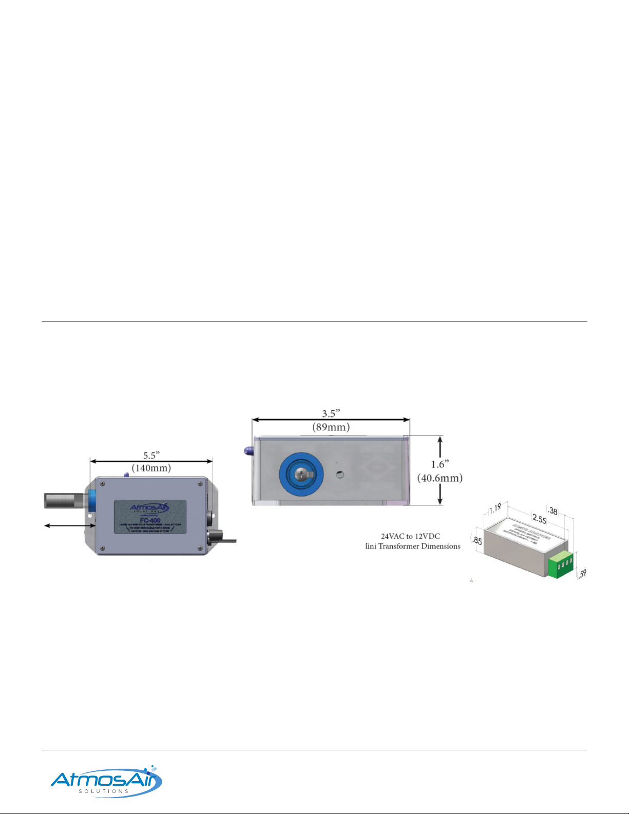
FC-400 Diagram
AtmosAir FC-400 Layout:
A. Power Input
B. Ionization Tube
C. Blue LED Power Light
D. Mounting Holes
E. Fuse Holder
F. 24 VAC to 12 VAC Mini Transformer
Overall Mounting Plate Dimensions:
152.40mm (6”) L x 88.90mm (3.5”) W x 40.64mm (1.6”) H

Installation, Operation & Maintenance Guide FC-400 Series 5
1-888-MY-AIR11 CAG-06-21-003 AtmosAir.com
02 INSTALLATION
AtmosAir FC-400 series equipment are mounted using the baseplate mounting ange. The units operate best when located after
all lters, coils, and fans. Various mounting arrangements are possible; however, the available options may be limited due to size
and conguration restrictions. When mounted, the FC-400 ionization system should not be exposed to condensing moisture or
excessive heat (refer to the Product Submittal for maximum environmental temperature specications). The AtmosAir FC-400
operates on 100-250 VAC, 50/60 Hz. The tube and electrode contacts should not come into contact with any conductive surface. A
minimum 38.1mm (1.5”) clearance around the tube is recommended.
Mechanical Installation
1. Carefully remove the equipment from its shipping container.
Inspect the box, components, and tubes for damage. Verify
that the unit’s voltage rating is the same as the available
voltage, 100-250 VAC 50/60 Hz.
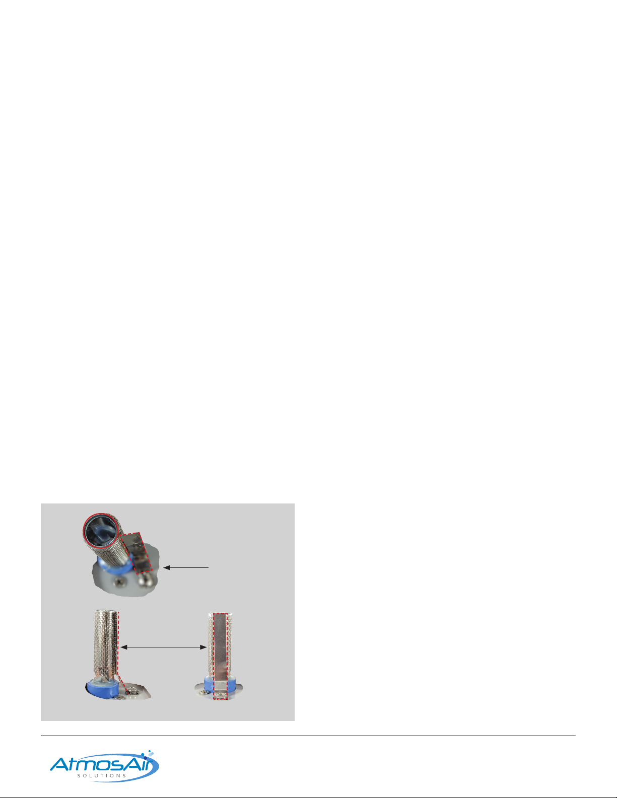
2. Install the ionization tube: Gently pull the conductor strap
back to allow the tube to turn freely; screw the end screw of
the tube into the tube-holder hand-tight. Ensure that the tube
is FULLY SEATED.
3. Once the tube is secure, return the conductor strap to
its normal position and ensure solid, at, and continuous
contact is made with the tube’s outer mesh.
(See page 8.)
!!!WARNING!!!
The secondary voltage to the ionization tubes can be as high as 3000 volts AC. Do NOT connect to power before the installation is complete and all
personnel are aware of imminent operation. Always disconnect power to the unit before handling any of the components.
Electrical
Connection Nut
B-Tube Screw SEATEDNOT FULLY
SEATED Tube Holder
Fig. 2.1a Fig. 2.1b
4. Location and Orientation: Install the unit downstream of
lters, coils, and fans with tubes perpendicular to airow
whenever possible. Contact AtmosAir Engineering for
Installations outside this scope.
5. Mark the drill holes for the self-tapping screws to mount the
FC-400.
6. Afx the unit securely using self-tapping screws. Do not over-
tighten, this may strip the screw-hole.
7. Units should be installed to allow easy access for
maintenance. Install units so that the power adjustment
knob, fuse, and status light are easily accessible, variable, and
visible.

Installation, Operation & Maintenance Guide FC-400 Series 6
1-888-MY-AIR11 CAG-06-21-003 AtmosAir.com
Electrical Installation
■AtmosAir FC-400 series systems require an average of 4.5 watts per unit.
■Follow proper electrical procedures, guidelines, and codes for providing power supplies to the systems. Including
requirements for conduit, sufcient ampacity, phase balancing, etc. Electrical installation should be performed by a qualied
electrician.
■Field-install a power plug outlet or power receptacle within 1.83 meters (6’) of the unit(s).
■Each FC-400 series unit is shipped with an 2.44 meters (8’) power cord with a eld install pair of wire hot/neutral connector on
one end and a quick-disconnect plug on the other end. The FC-400FM has a polarized quick-disconnect on the unit. Each unit is
shipped with two wiring options per country-specic requirements:
1. Two-conductor, eld wire connection (No Ground)
2. NEMA 5-15 two-prong plug adapter
Caution!
A non-functioning LED light may improperly indicate that the system is not functioning. Be sure to disconnect from the main power before performing
maintenance or troubleshooting the system.
!!!WARNING!!!
THE SECONDARY VOLTAGE TO THE IONIZATION TUBE CAN BE AS HIGH AS
3000 VOLTS AC. DO NOT CONNECT TO POWER BEFORE THE INSTALLATION IS COMPLETE
AND ALL PERSONNEL ARE AWARE OF IMMINENT OPERATION. ALWAYS DISCONNECT
POWER TO THE UNIT BEFORE HANDLING ANY OF THE COMPONENTS.

Installation, Operation & Maintenance Guide FC-400 Series 7
1-888-MY-AIR11 CAG-06-21-003 AtmosAir.com
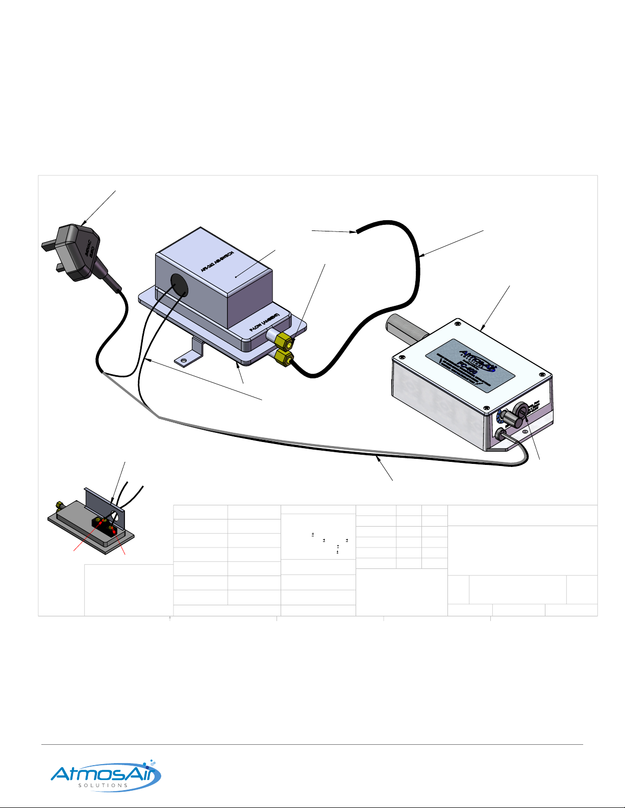
BLACK (HOT) WIRE TO N/O
NORMALLY OPEN AND
COM
AIRFLOW SAMPLING TUBE
INSERT 6" INTO AHU OR DUCT AFTER
FAN, AIRFLOW INTO TUBE END.
SILICONE IN PLACE
LEAVE OPEN TO
AMBIENT AIR
LID IS REMOVABLE
1/4" POLYETHYLENE
TUBING
MOUNT ON DUCT OR AHU
JUNCTION BOX
120 VAC
LO
HI
COMMON
NORM
OPEN
AFS 262
WIRING
GREEN SHRINK
TUBES
FEMALE SPADE TERMINALS
FOR FIELD CONNECTION
USA NEMA 5 PLUG
120VAC 60Hz IN,
12VDC OUT
12VDC
.500mA FUSE
5mm x20mm glass
ATMOSAIR FC-400
OR FC-400FM
FC-400/AFS262
DO NOT SCALE DRAWING
FIELD
WIRING DIAGRAM
FC-400 SERIES TO AFS-262
AIRSWITCH
SHEET 1 OF 1
UNLESS OTHERWISE SPECIFIED:
SCALE: 1:3
REV.
C
DWG. NO.
A
SIZE
TITLE:
NAME
DATE
COMMENTS: FIELD WIRING DIAGRAM
FOR CONNECTING FC-400 SERIES TO
AFS-262 AIR SWITCH TO LINE VOLTAGE
Q.A.
Rev C SB 3-12-21
ENG APPR. TA 2-21-19
2/21/19
DRAWN HRG 2-21-19
FINISH
MATERIAL
INTERPRET GEOMETRIC
TOLERANCING PER:
DIMENSIONS ARE IN INCHES
TOLERANCES:
FRACTIONAL
.010
ANGULAR: MACH
BEND
TWO PLACE DECIMAL
.010
THREE PLACE DECIMAL
APPLICATION
USED ON
NEXT ASSY
PROPRIETARY AND CONFIDENTIAL
THE INFORMATION CONTAINED IN THIS
DRAWING IS THE SOLE PROPERTY OF
ATMOSAIR SOLUTIONS. ANY
REPRODUCTION IN PART OR AS A WHOLE
WITHOUT THE WRITTEN PERMISSION OF
ATMOSAIR SOLUTIONS IS PROHIBITED.
5
4
3
2
1
ATMOSAIR SOLUTIONS
FC-400 SERIES
SERIES TO
AFS-262
CONNECTIONS
03 FIELD WIRING DIAGRAMS
Installation, Operation & Maintenance Guide FC-400 Series 8
1-888-MY-AIR11 CAG-06-21-003 AtmosAir.com
BLACK (HOT) WIRE TO N/O
NORMALLY OPEN AND
COM
AIRFLOW SAMPLING TUBE
INSERT 6" INTO AHU OR DUCT AFTER
FAN, AIRFLOW INTO TUBE END.
SILICONE IN PLACE
LEAVE OPEN TO
AMBIENT AIR
LID IS REMOVABLE
1/4" POLYETHYLENE
TUBING
MOUNT ON DUCT OR AHU
COMMON
NORM
OPEN
AFS 262
WIRING
ATMOSAIR FC-400
OR FC-400FM
12VDC
1Amp FUSE
5mm x20mm
glass
240 VAC
50/60HZ
'EURO' PLUG
WITH 13 AMP
INTEGRAL FUSE
FC-400/AFS262
DO NOT SCALE DRAWING
FIELD
WIRING DIAGRAM
FC-400 SERIES TO AFS-262
AIRSWITCH (PLUG)
SHEET 1 OF 1
UNLESS OTHERWISE SPECIFIED:
SCALE: 1:3
REV.
A
DWG. NO.
A
SIZE
TITLE:
NAME
DATE
COMMENTS: FIELD WIRING DIAGRAM
FOR CONNECTING FC-400 SERIES TO
AFS-262 AIR SWITCH TO PLUG
Q.A.
ENG APPR. HG 3-12-21
DRAWN SB 3-12-21
FINISH
MATERIAL
INTERPRET GEOMETRIC
TOLERANCING PER:
DIMENSIONS ARE IN INCHES
TOLERANCES:
FRACTIONAL
.010
ANGULAR: MACH
BEND
TWO PLACE DECIMAL
.010
THREE PLACE DECIMAL
APPLICATION
USED ON
NEXT ASSY
PROPRIETARY AND CONFIDENTIAL
THE INFORMATION CONTAINED IN THIS
DRAWING IS THE SOLE PROPERTY OF
ATMOSAIR SOLUTIONS. ANY
REPRODUCTION IN PART OR AS A WHOLE
WITHOUT THE WRITTEN PERMISSION OF
ATMOSAIR SOLUTIONS IS PROHIBITED.
5
4
3
2
1
ATMOSAIR SOLUTIONS
FC-400 SERIES
SERIES TO
AFS-262
CONNECTIONS
03 FIELD WIRING DIAGRAMS CONTINUED

Installation, Operation & Maintenance Guide FC-400 Series 9
1-888-MY-AIR11 CAG-06-21-003 AtmosAir.com
4"-6"
21 GAUGE
48"
18 GAUGE
24VAC
(NO POLARITY)
12VDC
(POLARIZED)
BLACK -
WHITE
WHITE
RED +
BLACK -
RED +
MOUNT INTO 2.5"
HOLE IN DUCT
ATMOSAIR FC-400
OR FC-400FM
DO NOT SCALE DRAWING
FC-400 SERIES
24VAC INPUT
SHEET 1 OF 1
3/19/21
3/19/21
HG
UNLESS OTHERWISE SPECIFIED:
SCALE: 1:4
WEIGHT:
REV.
A
Created: 3/19/2021
A
SIZE
TITLE:
ATMOSAIR SOLUTIONS
NAME
DATE
PRODUCTION APPR.
ENG APPR.
CHECKED
DRAWN SB
FINISH
MATERIAL
INTERPRET GEOMETRIC
TOLERANCING PER:
DIMENSIONS ARE IN INCHES
TOLERANCES:
FRACTIONAL
.xxx
ANGULAR: MACH
.xxx BEND
TWO PLACE DECIMAL
.xxx
THREE PLACE DECIMAL
APPLICATION
USED ON
NEXT ASSY
PROPRIETARY AND CONFIDENTIAL
THE INFORMATION CONTAINED IN THIS
DRAWING IS THE SOLE PROPERTY OF
ATMOSAIR SOLUTIONS. ANY
REPRODUCTION IN PART OR AS A WHOLE
WITHOUT THE WRITTEN PERMISSION OF
ATMOSAIR SOLUTIONS IS PROHIBITED.
5
4
3
2
1
Last Saved: 3/22/2021
XXX
XXX
COMMENTS:
XXX
XXX
XXX
JS
03 FIELD WIRING DIAGRAMS CONTINUED

Installation, Operation & Maintenance Guide FC-400 Series 10
1-888-MY-AIR11 CAG-06-21-003 AtmosAir.com
2.5"
POSSIBLE
POSSIBLE
POSSIBLE
ATMOSAIR
FC-400 FM
12VDC
5' CABLE
120VAC TO 240VAC
AUTO SWITCHING
TRANSFORMER
GREEN SHRINK
TUBES
FEMALE SPADE
TERMINALS
FIELD WIRING
CONNECTION
(SUPPLIED)
5' CABLE
120/240 VAC
JCT. BOX
DO NOT SCALE DRAWING
TYPICAL AIR DUCT
FC-400 FM
MOUNTING
SHEET 1 OF 1
3/25/21
3/25/21
HG
SB
UNLESS OTHERWISE SPECIFIED:
SCALE: 1:4
WEIGHT:
REV.
A
Created: 3/26/2021
A
SIZE
TITLE:
ATMOSAIR SOLUTIONS
NAME
DATE
PRODUCTION APPR.
ENG APPR.
CHECKED
DRAWN
FINISH
MATERIAL
INTERPRET GEOMETRIC
TOLERANCING PER:
DIMENSIONS ARE IN INCHES
TOLERANCES:
FRACTIONAL
.xxx
ANGULAR: MACH
.xxx BEND
TWO PLACE DECIMAL
.xxx
THREE PLACE DECIMAL
APPLICATION
USED ON
NEXT ASSY
PROPRIETARY AND CONFIDENTIAL
THE INFORMATION CONTAINED IN THIS
DRAWING IS THE SOLE PROPERTY OF
ATMOSAIR SOLUTIONS. ANY
REPRODUCTION IN PART OR AS A WHOLE
WITHOUT THE WRITTEN PERMISSION OF
ATMOSAIR SOLUTIONS IS PROHIBITED.
5
4
3
2
1
Last Saved: 3/26/2021
XXX
XXX
COMMENTS:
XXX
XXX
XXX
JS
03 FIELD WIRING DIAGRAMS CONTINUED

Installation, Operation & Maintenance Guide FC-400 Series 11
1-888-MY-AIR11 CAG-06-21-003 AtmosAir.com
RETURN
SUPPLY
FAN
POSSIBLE
POSSIBLE TO INSTALL
IN RETURN
POSSIBLE
FILTER
B
12VDC
A
DETAIL B
UNIVERSAL SS304
MOUNTING BRACKET
PROVIDED
STANDARD
CAN BE BENT
PER APPLICATION
DETAIL A
FEMALE SPADE
TERMINALS
GREEN SHRINK
TUBES
120VAC TO 240VAC
AUTO SWITCHING
TRANSFORMER
FC-400 UNIT TYPICALLY INSTALLED
IN SUPPLY, HOWEVER UNDER
SPECIAL CIRCUMSTANCES
CAN BE INSTALLED IN RETURN
120/240VAC
SOURCE
AIRFLOW
DO NOT SCALE DRAWING
TYPICAL VERTICAL
FAN COIL FC-400
MOUNTING
SHEET 1 OF 1
3/25/21
3/25/21
HG
UNLESS OTHERWISE SPECIFIED:
SCALE: 1:4
WEIGHT:
REV.
A
Created: 3/25/2021
A
SIZE
TITLE:
ATMOSAIR SOLUTIONS
NAME
DATE
PRODUCTION APPR.
ENG APPR.
CHECKED
DRAWN SB
FINISH
MATERIAL
INTERPRET GEOMETRIC
TOLERANCING PER:
DIMENSIONS ARE IN INCHES
TOLERANCES:
FRACTIONAL
.xxx
ANGULAR: MACH
.xxx BEND
TWO PLACE DECIMAL
.xxx
THREE PLACE DECIMAL
APPLICATION
USED ON
NEXT ASSY
PROPRIETARY AND CONFIDENTIAL
THE INFORMATION CONTAINED IN THIS
DRAWING IS THE SOLE PROPERTY OF
ATMOSAIR SOLUTIONS. ANY
REPRODUCTION IN PART OR AS A WHOLE
WITHOUT THE WRITTEN PERMISSION OF
ATMOSAIR SOLUTIONS IS PROHIBITED.
5
4
3
2
1
Last Saved: 3/26/2021
XXX
XXX
COMMENTS:
XXX
XXX
XXX
JS
03 FIELD WIRING DIAGRAMS CONTINUED

Installation, Operation & Maintenance Guide FC-400 Series 12
1-888-MY-AIR11 CAG-06-21-003 AtmosAir.com
Recommended Maintenance Procedures:
■Visually check the performance of the system by
checking the blue light on the unit. If not, proceed to the
troubleshooting section for repair. Maintain a physical
distance between all personnel and the tubes while
system is operating or turned on.
■Optional: Check performance using a high voltage
probe paired with a multimeter (minimum of 5000 V
probe). Contact AtmosAir for additional minimum probe
specications. Follow proper safety procedures for
dealing with high voltages. If you are uncertain, do NOT
perform any maintenance with the power on and proceed
to the next step.
■Disconnect the system from the main power before
performing any maintenance steps.
■Inspect the unit box, plastic tube caps, and tube-
mounting area. Remove particles from mounting area,
and thoroughly wipe clean any tracks or grooves that may
have developed in the plate or caps.
■Inspect connections: tightness of all nuts and screws;
remove deposits on the connections using wire brush or
similar tool - it may be necessary to remove the tubes for
this step.
■It may be benecial to clean the tubes to improve
performance. The tubes can be cleaned using an air
compressor for a quick clean, or more thoroughly with
cleaning solutions. Do not immerse the tubes in water.
Ensure that the tubes and mesh are completely dry
before re-installing.
04 OPERATION
Once the system is properly installed and all personnel are
clear of the high voltage tubes, the system can be turned on:
1. Ensure the ionization power knob is turned to the
appropriate quadrant: from low to high clockwise.
Typically, it is suggested to start at a baseline of 50%
ionization. Twenty-four hours later, re-evaluate your air
quality and adjust accordingly.
2. Plug the power cord on the FC-400 ionization system into
the plug receptacle.
3. Once the FC-400 system is plugged in the system will be
on. Check that the blue embedded LED light is lit. The LED
is programmed to indicate that the system is on, ionization
has been activated, and high voltage is being sent to the
tube.
4. Settings are determined upon commissioning and
installation with the Criteria below:
5. The system is intended to deliver ions into the treated area
such that the ion levels should be between 350 and 1500
negative ions/cm3. The desired ion increase is dependent
on many factors, including space, use, contaminant level,
humidity RH, and distribution effectiveness. An authorized
AtmosAir design consultant should recommend the
desired ion increase and appropriate system layout.
05 MAINTENANCE
REQUIREMENTS
Caution!
A non-functioning LED light may improperly indicate that the system
is not functioning. Be sure to disconnect from the main power before
performing maintenance or troubleshooting the system.
The maintenance requirements on an AtmosAir system are
mainly site-dependent; a heavily contaminated environment
may require more frequent inspection and maintenance.
Annual system maintenance is recommended. A bi annual
tube replacement is required. Your local AtmosAir dealer can
provide you with an annual service contract.
Tube Replacements:
Bi-annual tube inspections are recommended, in addition to
tube replacements once every two years as the production
efciency slowly declines over time due to the stress caused
by plasma and (lack of) cleanliness of the electrodes. Old
or excessively dirty tubes can also put undue stress on the
transformer causing premature failure.
Installation, Operation & Maintenance Guide FC-400 Series 13
1-888-MY-AIR11 CAG-06-21-003 AtmosAir.com
06 TROUBLESHOOTING
In the event that the system is not functioning, follow these
steps IN ORDER:
1. Check the fuse. If it is blown, replace it with the appropriately
sized slow-blow 500 mA (0.5 Amps) glass 5 mm × 20 mm
fuse rated at 250 V and continue to the next step.
2. Check that the main power supply is sending the correct
power to the unit (100-250 VAC).
3. If the main power is controlled or any other power limiting
device is installed, check that these are not preventing power
from being sent to the system.
4. If power is reaching the unit and it was necessary to replace
the fuse, the next step is to determine whether there is a
fault in the system or a tube. First, to check that the system’s
power is functioning, set the ionization power knob and
the power switch both to the ‘off’ position. Make sure all
personnel are clear of the high voltage tubes, then re-
connect the power supply. Flip the power switch to ‘on’ and
observe the green light. If the light does not turn on, there
is still a problem with delivering power to the system. If all
external sources of failure are eliminated, the system should
be serviced by a qualied AtmosAir technician. Refer to the
contact information at the bottom of this page.
5. Check that the spring tang is making CLEAN, FLAT-TO-
TUBE contact with the tube as shown below:
The next step is to determine the cause of the failure, or
blown fuse. Typically, failures are caused by arcing between
the inner and outer electrodes, or between one electrode
and ground. Often, this occurs either because the tube
isn’t properly seated, or because of damaged tubes or dirty
and/or wet conditions that have allowed carbon tracking
to temporarily connect two electrodes and/or a grounding
point electrically.
6. Inspect the mounting plate for tracking evidence.
7. Inspect the tubes for cracks, pitting, or other degeneration
of the dielectric material that causes the dielectric to fail
and arcing to occur.
8. If physical inspection has not revealed the cause of failure,
one may carefully observe the tubes as the ionization
system is turned on to determine whether arcing is
occurring at a particular tube. The fuse will usually blow,
again, but for a short time, one may observe the cause
of the power surge in the form of a visual or audio cue.
Usually, a failing tube can be determined in a darkened
room by looking for a ash or arc from the failing tube.
9. If the fuse blows, then the system should be serviced by
a qualied AtmosAir Technician. You can contact repair
services at RMA@atmosair.com or by contacting us at
1-888-MY-AIR11.
10. If the fuse continuously blows, then the system should be
serviced by a qualied AtmosAir technician. DISCONTINUE
USE IMMEDIATELY!
11. Otherwise, replace the damaged tube(s), clean and
smooth any mounting plate or end cap carbon tracking,
and return the system to service.
Not Acceptable
Acceptable
Fig. 5a
Fig. 5b Fig. 5c

Installation, Operation & Maintenance Guide FC-400 Series 14
1-888-MY-AIR11 CAG-06-21-003 AtmosAir.com
07 EXPLANATION OF TECHNOLOGY
AtmosAir Solutions’ ™ mission is to bring and restore every indoor environment the same clean and pure quality air that is typically
found at higher mountain elevations.
AtmosAir’s unique and proven air purication process signicantly reduces mold, controls the spread of bacteria and airborne
viruses, and reduces airborne particles that evade normal ltration solutions.
AtmosAir equipment uses non-thermal plasma technologies to generate bi-polar Ionization that attacks and breaks down odors
and contaminants.

Installation, Operation & Maintenance Guide FC-400 Series 15
1-888-MY-AIR11 CAG-06-21-003 AtmosAir.com
y
y
CLEAN AIR GROUP, INC. – PRODUCT WARRANTY
Clean Air Group, Inc. d/b/a AtmosAir Solutions (“Clean Air Group”) warrants to the original purchaser of this product (“Customer”),
that should it prove to be defective by reason of improper materials or workmanship, for twenty-four (24) months from the date
of installation, or twenty-seven (27) months from the date of Clean Air Group’s delivery of the product, whichever occurs first,
Clean Air Group shall repair or replace the product without charge to the Customer. Proof of malfunction and return of the non-
working product must be presented by the Customer if submitting a warranty claim. This warranty is invalid if the factory applied
serial number has been altered or removed from the product. This warranty does not cover damage due to acts of God, misuse,
abuse, negligence, or modification of or to any part of the product. This warranty does not cover damage due to improper
installation, operation or maintenance, connection to improper voltage or electrical supply, or repair by anyone other than an
authorized Clean Air Group service provider. To obtain warranty service the Customer must: (1) provide proof of purchase in
the form of a Bill of Sale or receipted invoice, with evidence that the product is within the warranty period; (2) request a Return
Merchandise Authorization (“RMA”) from Clean Air Group prior to shipping; and (3) ship the product with the RMA to Clean Air
Group, freight prepaid, in either its original packaging or packaging affording an equal degree of protection. The product should
be delivered to AtmosAir, 2115 East Cedar Street, Suite 6, Tempe, AZ 85281. All transportation charges and shipping expenses
are the Customer’s responsibility. Clean Air Group will return the product by the same method it receives the product. A product
returned for repair after the warranty period, or that shows damage outside of the warranty coverage described herein, shall be
repaired for a reasonable charge as determined by Clean Air Group. The Customer will be advised of the cost of repair or
replacement before Clean Air Group proceeds.
THE OBLIGATIONS OF CLEAN AIR GROUP HERIN ARE EXPRESSLY GRANTED IN LIEU OF ALL WARRANTS, WHETHER
EXPRESS OR IMPLIED, INCLUDING BUT NOT LIMITED TO IMPLIED WARRANTIES OF MERCHANTABILITY AND FITNESS
FOR A PARTICULAR PURPOSE. ALL IMPLIED WARRANTIES INCLUDING WARRANTIES OF MERCHANTABILITY AND
FITNESS FOR PARTICULAR PURPOSE ARE LIMITED TO THE TERM OF THE EXPRESS WARRANTY GRANTED HEREIN.
Some states do not allow limitations on how long an implied warranty lasts, so the foregoing limitation or exclusion may not apply
to you.
With the exception of damages resulting from Clean Air Group’s failure to comply with any obligation under federal or state
warranty laws, Clean Air Group SHALL NOT BE LIABLE TO THE CUSTOMER OR ANY OTHER PERSON OR THIRD PARTY
FOR ANY DAMAGES, INCLUDING BUT NOT LIMITED TO CONSEQUENTIAL, SPECIAL, INDIRECT, INCIDENTAL AND
PUNITIVE DAMAGES AND/OR DAMAGES BY REASON OF INJURY TO ANY PERSON DUE TO ANY DEFECT OR
MALFUNCTION OF THE PRODUCT OR ANY PART OR PARTS THEREOF OR FOR ANY OTHER REASON. This warranty
gives you specific legal rights and you may have rights which vary from state to state. If your product is defective please contact
Clean Air Group or the dealer where you purchased the unit.
Disclaimer: The air purification technology provided by AtmosAir is intended to improve air quality. It is not intended to replace
reasonable precautions to prevent the transmission of airborne contaminants. Customer, its employees, invitees and all persons
having access to the serviced premises should comply with all applicable public health laws and guidelines issued by federal,
state and local governments and health authorities such as the Centers for Disease Control and Prevention (CDC). These
precautions include but are not limited to wearing face masks, social distancing, hand hygiene and appropriate sanitizing and
disinfecting. Clean Air Group does not assert that its products can protect people from viruses, bacteria or other airborne
contaminants, expressly excludes liability for loss or damage arising from any such claims, and does not assume any liability for
the consequences arising out of the application, use or misuse of its products, including any injury or damage to any person or
damage to any property as a matter of product liability, negligence, contract or otherwise.
Manufacturer,
Anthony M. Abate
Chief Technology Officer
Clean Air Group, Inc.
08 PRODUCT WARRANTY
Table of contents
Other cleanAIR Air Cleaner manuals

cleanAIR
cleanAIR Optima CA-803 User manual

cleanAIR
cleanAIR AtmosAir Everest User manual

cleanAIR
cleanAIR AerGO NA-041-R01 User manual

cleanAIR
cleanAIR Optima CA-267 User manual

cleanAIR
cleanAIR D2000 Owner's manual

cleanAIR
cleanAIR RESQUE 100 User manual

cleanAIR
cleanAIR AerGO A1 P R SL User manual

cleanAIR
cleanAIR AtmosAir 500 Series Technical Document

cleanAIR
cleanAIR Optima CA-401 User manual


