Cleanfix KS 1100 B HD User manual

KS 1100 B HD
KS 1100 B
Swiss Made Quality.
08/2012BA KS1100.000-EN
Swiss Made Quality.
Swiss Made Quality.
Englisch

1
Contents
Introduction Page
To these operation instructions.................................................................2
Symbols used in this manual..................................................................2
Safety indications......................................................................................3
Appropriate use........................................................................................3
Product description.............................................................................................................4
Operating panel........................................................................................4
Safety instructions................................................................................................................5
Applications..............................................................................................5
Safety devices.......................................................................................................................6
Initial start-up, standard, optional.............................................................6
Operation................................................................................................................................7
Safety instructions....................................................................................7
Adjust the driver's seat, driving / Start......................................................7
Driving forward, reverse, acoustic signal (optional)...................................7
Sweeping operation, safety, operating the sweeper..............................8/9
Operation of extraction, filter cleaning, parking.........................................9
Dust bin emptying, removing + installing dust box..................................10
Hydraulic high dump...............................................................................10
Filter replacement, expansion, installation.............................................11
Machine cleaning................................................................................................................12
Maintenance and Service.................................................................................................12
Safety instructions..................................................................................12
Side brushes..........................................................................................13
- Side brushes exchange, installation side brush...................................13
- Side brushes readjustment.................................................................13
Cylindrical brush...................................................................................14
- Cylindrical brush exchange, Installation of the cylindrical brush...........14
- Cylindrical brush readjustment.............................................................15
Batteriy..................................................................................................16
- Safety instructions for the use of batteries............................................16
- Battery charging...................................................................................17
Brakes, Adjust the brakes, the brake control function.............................18
Functionality of the brake, Other adjustment..........................................18
Fuses, safety information........................................................................19
Wheels and steering, broom drive...........................................................19
Maintenance Table..............................................................................................................20
Errors and solutions...........................................................................................................21
Circuit diagram KS 1100 B.................................................................................................22
Circuit diagram KS 1100 B HD...........................................................................................23
Technical Data.....................................................................................................................24
Applied Standards, Product label, Disposal, environmental protection.................25
Declaration of Conformity.................................................................................................26
Service..................................................................................................................................27
Spare Parts...........................................................................................................................27
KS 1100 - Englisch

2
Introduction
To this Operation Instructions and Maintenance Manual
In this paragraph you will find information about how this manual is structured
and explanations for the used signs and symbols.
This manaul contains instructions on how to use the ride-on-sweeper KS1100 B and
KS 1100 B HD.
Our products are being improved continuously, for this reason we cannot include all tech-
nical adaptions within this manual by the date of printing. If you should have any questions,
please feel free to contact our Service for explanations and advise.
This Operation Instructions and Maintenance Manual has to be read and been understood
by all persons who will use or operate or maintain this ride-onsweeper KS1100.
Besides the Operation Manual and the laws and rules abiding in the country of use the
applicant should take all necessary measures to apply and take into consideration all
existing Health and Safety measures to prevent accidents and allow for professional on the
job conditions.
Symbols used in the manual
Following symbols and descriptions are used in this manual for very impor-
tant indications.
Danger!
All dangers for persons which
could lead to serious Injuries or
even death are marked by this
symbol and safety instructons.
Caution!
This symbol stands for possible
dangerous situations or when
light injuries could occur.
Attention!
This symbol is used to indicate
dangers which can damage
machines or auxiliary equipment.
☞This symbol is used for hints
which indicate how to use
the ride-on-sweeper.
•This symbol in the text
indicates that this job has
to be done
-A dash in front of the text
means: This is part of an
itemization
KS 1100 - Englisch

3
Introduction
Appropriate use
The ride-on-sweeper is only designed for
sweeping dry wastes on paved floors e.g.
car parks, industrial halls, storage halls,
pavements.
Never ever use the machine under any
circumstances whatsoever to sweep
flammable or explosive material.
Any other use or unauthorized use which
is not according to the specifications and
determination are prohibited.
The manufacturer cannot be made
responsible and will not be liable for any
damages or consequential damages
resulting out of such a use.
The applicant will bear such risks
and hazards.
The ride-on-sweeper is not intended
for sweeping of strings, ropes, wires
or similiar objects.
For appropriate use according to the
sweepers designation it is important
to abide to this manual and to comply
with all inspection and maintenance
instruction.
Safety indications
The ride-on-sweeper KS1100 ist built
according to the latest standards and
safety regulations. All the same it can
never be foreclosed that life threatening
dangers can occur for the user or for third
parties or restrictions for the ride-on-
sweeper and damage to material assets
may happen.
For this reason the Ride-on-Sweeper
must only be used when in perfect condi-
tion, used in a proper and foreseen way.
At all times the Ride-on-Sweeper should
be used taking all Health and Safety regu-
lations into consideration, the user be
made aware of dangers which can occur
by properly reading and understanding
this Operation Instructions and Mainte-
nance Manual.
All errors which may affect any aspects of
Health and Safety must be solved imme-
diately. Always keep this Manual at the
site where the Ride-on-Sweeper is being
used for quick reference! Observe and
consider all other applicable rules and
laws which abide for accident prevention
an for protection of the environment!
Do not execute any changes, add or
rebuild any components on the Ride-on-
Sweeper without prior consent of the
Manufacturer.
Spare parts must abide to the technical
requirements stated by the manufacturer.
This is always assured by the purchasing
of Original spare parts.
Always follow and indicated maintenance
intervals of the supplier or the indicated
maintenance jobs and intervals mentio-
nend in this Operation Instructiions and
Maintenance Manual.
Please make sure that all waste items are
disposed of in safe and ecological way of
all operational supply items, additives or
replacement parts.! Prevent use by
unauthorized persons, e.g. by pulling out
the keys after use.
KS 1100 - Englisch

4
Product description
The ride-on-sweeper is driven by electro-motors. The KS1100 does the sweeping job by
means of 2 swivel side brushes which brush the wastes to the central cylindrical brush
which is positioned parallel to the driving direction. The cylindrical brush then throws over
the top all wastes into the waste bin behind. The dust which is raisen and dispersed can be
disposed of if required by the vacuum motor which sucks away the dust to the multi-layer
filter unit integrated at the back of the machine. This multi-layer filter can be cleaned by
means of activating the electrical vibrating unit.
Operator panel (without overhead discharge)
1
0
ON
OFF
ON
OFF
ON
OFF
1
0
ON
OFF
ON
OFF
ON
OFF
Vacuum motor switch
Switch for cylindrical
brush motor
Switch for swivel side
brush motors
Switch for filter
cleaning
Battery charge—Status indication
Battery status indicator (LEDs)
ON /OFF
switch with key
ON / OFF Key (0 or 1)
Emergency-Off / Main Switch
Switch for Vacuum motor
Switch for Cylindrical
brush motor
Switch for swivel side
brush motors
Main Power Key ON/OFF
or Emergency OFF
2 Position key „Lifting“:
lifting/lowering
Switch for filter cleaning device
Operator panel (with overhead discharge)
KS 1100 - Englisch

5
Safety instructions
Swiss Made Quality.
Handle to lift and drop the
cylindrical brush
Brake pedal with with
footoperated parking
brake
Accelerator
Head light
Front wheel
with brake
Excellent climbing ability 20%
360° turning
circle for perfect
manoevrability
Solid stainless steel frame as
bump protection with impact
resistant cover
Applications
1
0
ON
OFF
ON
OFF
ON
OFF
User-friendly Operator panel
Large, non-marking wheels
Side covering (behind is access for
Adjustment of the cylindrical brush
Filter, side brushes and
cylindrical brush are easily
accessible without the use
of tools
Steering column with steering
wheel and operator panel with: -
- Light switch - forwards / backwards
leverl - Drive backwards-alarm
(optional)
Left and right lever on the
steering column to lift
and sink both side brushes
Adjustable seat to allow an ergonomic
Two self-swivelling side-
brushes for large sweepways
●Parking spaces
●Schoolyard
●Petrol station
●Underground park
●Shopping centres
●Warehouses
Simple emptying
KS 1100 - Englisch
Extra large hopper,
ideal use by means of
overthrow system

6
Safety devices
The Ride-On-Sweeper starts only when,
- the battery mains switch (emergency.-
Off) And the start switch with key is in
ON–position;
- Someone sits in the driving seat and
the seat contact is activated and addi-
tionally the accelarator pedal is
pressed down.
If the direction level (forwards/backwards)
at the steering column is in backwards
position, then an acoustic signal is activa-
ted. (optional)
Initial– Start-Up
The Ride-on-Sweeper is delivered as
standard version withou batteries and
without charger.
Optional:
The Ride-On-Sweeper can be delivered
with batteries and charger. The Ride-on-
Sweeper can be delivered with hydrau-
lisch overhead waste-box emptying.
Standard
• Open the transport packing.
• Remove the complete main cover. Lift
the main cover at the back and secure
the open position by using the support
holder.
• Place the batteries inside the machine.
• Connect the batteries to the power
supply according to the Technical Data
and Circuit diagramm/Wiring plan.
• Close the main cover again and put
the support holder back into position.
• Mount the side brushes (page 13)
The Ride-On-Sweeper is now functional
and ready for operation.
• Drive the Ride-On-Sweeper out of the
transport packing down from the
wooden palett by using the ramp.
☞ Make sure to use the closed ramp.
The ramp must be designed
in such a way that not only the
front wheel, but also the rear-
drive-wheels can drive onto, over and
down and off the ramp.
If these instructions are not followed then
the mechanical functions of the Ride On-
Sweeper could be considerably damaged.
The power supply respectively the start
procedure must be interrupted in the
following cases:
Hence, the following is essential:
• The main cover can only be opened if
the Main switch is in OFF position, i.e.
the lever is turned in OFF position which
then allows free opening.
• The side covers and other screwed /
bolted machine parts are only allowed
to be removed if the EMERGENCY-
OFF switch is turned to OFF position
and the key has been removed!
Optional:
• The Ride-On-Sweeper is equipped
with batteries.
• Open the transport packing.
• Open the main cover of the machine.
• Secure the open position of the main
cover with the cover support rod. The
cover has drill holes on the underside.
• Stick the cover support rod into the
drill hole.
• Connect the Plus-pole of the battery.
• Close the main cover.
• Mount the side brushes (see page 13)
• Drive the Ride-On-Sweeper over the
ramp and out of the transport packing.
☞ Make sure to use a closed ramp.
The ramp must be designed
in such a way that not only the
front wheel, but also the rear-
drive-wheels can drive onto, over and
down and off the ramp.
If these instructions are not followed then
the mechanical functions of the Ride On-
Sweeper could be considerably damaged.
The Ride-on-Sweeper is now functionable.
KS 1100 - Englisch

7
Operation
Safety instructions
The Ride-on-Sweeper can only be used
by reliable persons. Only trained and well
instructed persons shall be used. The
responsibilities must be clearly fixed.
Always check the Ride-On-Sweeper
before any drive and test the
functionability.and technical safety.
Do not use the machine if it should have a
defect. Only drive on the tracks and areas
which are strictly assigned for the Ride-
on-Sweeper. The Ride-On-Sweeper is
strictly designed for only one person to
use. The transportation of more than one
person is strictly forbidden.
Adjustment of the driver seat
Undo the seat fixation and move the
driver seat on the it‘s seat console until
you have found the suitable sitting
position.
Drive operation / Starting
the Sweeper
• Seat yourself on the drivers seat.
The Ride-on-Sweeper cannot be put
☞ into operation, if the drivers seat is
not exposed to weight pressure to
switch the contact.
• Check the position of the switch of
the lever on the operator panel.
• The Filter cleaning switch must be
in OFF (AUS) position.
• The red Main Switch must be in ON
(EIN) position.
• The Key switch must be ON
• Check the battery charge status- -
indication on the operator panel.
The luminious LED‘s shine in sequen-
ce and then show the effective char-
ging status of the batteries.
• Press the brake.
• Release the emergency-brake fixation
(next to the brake)
- Driving forwards:
• Move the lever switch to the front for
actuation „drive forwards“. Only when
☞the accelerator has been pressed
down, then the Ride-on- Sweeper will
start driving.
- Driving backwards:
• Move the lever switch to the back for
actuation „drive backwards“. Only
☞when the accelerator has been
pressed down, then the Ride-on-
Sweeper will go backwards.
An acoustic signal is optional
• The speed of the Ride-on-Sweeper
can be chosen variably when
☞pressing down the accelerator.
1
0
ON
OFF
ON
OFF
ON
OFF
Swiss Made Quality.
Brake pedal
Brake fixation
Accelerator
Light switch
Horn
Lever:
forward/backwards
KS 1100 - Englisch

8
Sweeping operation
Safety instructions
Do not switch on the vacuum motor when
sweeping wet areas/wastes This would
lead to a clogged filter and damage to the
vacuum motor. In closed rooms make
sure to have a proper room aeration.
Never sweep wastes dangerous to
health.
Operator panel (without overhead
disposal)
Operation of the cyclindrical brush
• Start the Ride-on-Sweeper
• Release the lever to lower the cylindri-
cal brush to the floor.
• Switch the Tip switch to ON to start
the cylindrical brush
☞ On the switch a control light will shine.
Stopping Cylindrical brush operation:
• Switch the Tipp switch for the cylind-
rical brush to OFF.
• Pull the lever for the cylindrical brush up-
wards and let it sideways fall in the latch.
Operation of the side brushes
• The side brushes are fixed to swivel
connections. When the side brushes
collide with an obstacle they swivel to
the side which prevents damage to
the Ride-on-Sweeper.
• Start the Ride-on-Sweeper.
• Release both levers which hold both
side brushes off the floor. The levers
are on the left and right side of the
steering pillar.
• Move the lever downwards.
• Switch the Tipp switch for side
brushes to ON position.
☞ On the switch a control light will shine.
The side brushes begin to rotate.
Ending the side brush operation:
• Switch off the Tipp switch for the
side brushes
• Pull both lever of the side brushes
upwards and let it fall in each latch.
• Engage the lever.
Switch for side brushes
1
0
ON
OFF
ON
OFF
ON
OFF
Switch for cylindrical brush
Switch for vacuum
motor (suction)
Emergency-Off—
Main Switch
Battery charge
status-indication
Switch for
filter cleaning
(vibration)
ON– and OFF Key switch
Swiss Made Quality.
2 levers to lift
and sink the
side brushes
1 lever to lower the
cylindrical brush
KS 1100 - Englisch

9
Sweeping operation
Operator panel
(without overhead disposal)
Vacuum operation
Vacuum operation helps preventing
Dust accumulation when sweeping.
• Start the Ride-on-Sweeper
• Switch on the Tipp switch for the suc-
tion motor.
☞A control light will shine on the
switch. The suction operation
begins.
Attention !
Do not switch on the vacuum
motor when cleaning wet areas/ wastes.
It will cause damage to the vacuum motor.
— To end the vacuum operation switch the
Tipp switch to Vacuum motor OFF.
Filter cleaning operation
The filter cleaning—vibration device pre-
vents that lamellas of the filter do not
clogg up with dust.
☞Switch off the vacuum operation.
Wait until the ventilator wheel stops
and stands still.
Press the Tipp switch 5-10 seconds long
for the filter cleaning.
The filter cleaning begins to work.
Switching off the Ride-on-Sweeper
• Press the brake pedal
• Secure the brake by pressing
additionally the small brake pedal
(„hand-brake) into the latch.
☞If the brake is released afterwards,
then the brake pedal must be kept
pressed down.
• Switch off all power supply
• Lift up both side brushes by using
both levers on the steering column.
• Latch the lifting / lower level for the
cylindrical brush.
• Turn the key into position 0 = OFF
and take the key out.
Turn the battery main switch
OFF and take it out of the
holder.
Danger !
Inappropriate use of the Ride-on-Sweeper can
lead to severe injuries to persons and heavy
damage to the equipment!
Prevent unauthorized persons to use the
Ride-on-Sweeper.
Never leave the operational Ride-on- Sweeper
unsupervised.
Pull out the battery mains switch key and the
key of the ON/OFF switch when leaving the
machine unattended.
(e.g. at the end of a job or days work the key
should be removed)
Keep the Mains Switch key and ON/OFF key
switch in separate places.
KS 1100 - Englisch
Switch for the side brushes
1
0
ON
OFF
ON
OFF
ON
OFF
Switch for the cylindrical
brush
Switch for cylindrical
brush
Switch for
cylindrical brush
Battery charge-
status indication
Switch for
filter cleaning
ON and OFF key switch
Lever to open a flap and allow large
wastes enter
(Wastes till 65mm) E.g. small PET bottles,...

10
Operation
KS 1100 - Englisch
Waste box emptying
The waste box is used to collect all
sweeped wastes. It can be found at the
back of the machine.
☞The Waste box / hopper must be
emptied regularly but latest after
each use.
Manual Emptying of the Waste Box
• Turn upwards both steel swivelcat-
ches which release the waste box.
They can be found on both sides
foteh waste box.
• Pull out the waste box along the
rails, by pulling upwards and holding
the handle of the waste box.
• The waste box can easily be removed
and put back inside the machine
again.
• Pull out the waste box completely.
• To empty the waste box grab inside
the grip of the handle.
Insertion of the waste box
• Place the waste box in front of the
entrance of the waste box opening
at the back of the Ride-on-Sweeper.
• Lift the waste box to the height where
it can enter the opening to the
guiding rails.
• Slide the waste box inside again
• As soon as the waste box is
completely inside the machine the
steel-swivel catches can easily be
moved downwards to lock position.
Hydraulic Overhead Waste Emptying
• When the waste box is full or ready for
emptying proceed according to the
Stepps 1 to 4 at the switches:
• First switch on the ON/OFF switch for
overhead waste box emptying.
• Then tip the rocker switch to Pos.1
(lift the waste box) and then let go
the rocker switch to middle position,
i.e. „hold“
• Now drive the Ride-on-Sweeper to
the foreseen waste container, close
enough backwards so that the
waste box is above the open waste
container.
• Pull the handhold for buckling (2)
• Push the handhold back to the home
position (3)
• Now you can press the rocker
switch „lower waste box“, pos.4.
Switch lifting / lowering
2-handhold for
buckling
1
0
ON
OFF
ON
OFF
ON
OFF
I
O
II
11
Operation
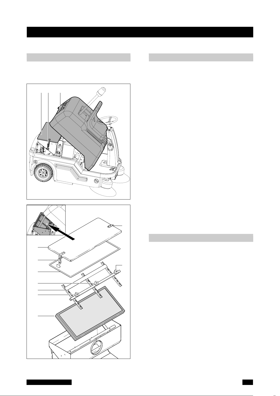
Dismantling
• Open the main cover. (A).
• Secure the main cover with the sup-
port rod in top position.
• The filter box cover (D) is held and
secured by two rubber latches (B).
• The inner lamellar filter plate with the
filter holder and the 3 star handles (C)
and held fixed.
• Loosen both rubber mounts (B) and
remove the air box- Cover (D) with
seal (E) up and away.
• Loosen the 3 star handles (C) to the
frame with plate filter is free.
Pull the plate filter (F) from the filter
box.
☞ Always replace the complete frame
with lamella-filter.
Mounting
• Insert the new lamella filter frame (F).
• Filter holder (G) and use disk filter
clamp with the 3 star knobs.
• The air box lid (D) onto the filter box
with seal (E).
• On each side of the air box lid, the
rubber-mount (B) down into place and
tighten.
• Carefully release the support rod
holding the machine cover and let it
down slowly and close.
Filter exchange
KS 1100 - Englisch
AD B
D
E
G
F
B
C
C
B
C
The integrated lamella filter separates the
fine dust. The lamella filter is cleaned by
electric activation of vibration unit.

12
Machine cleaning
The Ride-on-Sweeper is a machine with electrical components.
Attention !
Humidity damages electronic components.
Humidity can lead to creeping current and short circuits.
Never use high-pressure cleaners.
Attention !
Before doing any work on the Ride-on-Sweeper it is compulsory to first
TURN-OFF and the Main Switch (Emergency-Off Switch) and REMOVE
THE KEY in order to prevent unforeseen switching-on of the machine.
The opened main cover is to be secured by the support rod. Place the
support rod for the main cover in a safe and stable position.
Whenever working on electric and electronic parts of the machine it is
compulsory to first disconnect the negative terminal/pole of the battery!
Only use appropriate and faultless tools and equipment for your
maintenance and service work.
Every twelve (12) months, resp. 200 Operation hours, it will be neceessary to
have professional inspection of the Ride-on-Sweeper by an authorized and
competent person (primarly by the manufacturer or an authorized dealer or
trained specialist).
The results of this inspection must be kept to record in writing and to be
saved at least until the next inspection takes place.
KS 1100 - Englisch
Maintenance and Service
Safety instructions

13
the counter flange coming from the
side brush motor and is fixed tightly.
Side brushes adjustment
Due to wear and tear of the side brushes‘
bristles and the change in floor contact
height, it is necessary to readjust the side
brushes height from time to time.
• Turn-Off / Switch off the Ride-on-
Sweeper.
• Release the levers for both side
brushes and push them downwards.
• The side brushes are each fixed by
means of two supports. The right
support (bowden cable) is to lift or
lower the side brushes, the left sup-
port (butterfly handle screw) is used
to readjust the height of the brushes.
Maintenance and Service
Side brushes
Side brushes exchange
Removal of the side brushes
• Switch off of the Ride-on-Sweeper.
• Pull the levers of the side brushes
upwards.
• Locate both levers in their positions.
• Lift the side brush motor upwards in
order to get better access to the side
brushes.
• Unscrew the three fixation screws in
the centre of each side brush.
• Pull downwards each side brush.
• Replace the side brushes.
Mounting the Side Brushes
• Turn the 3 screw holes of the flange
plate of the side brushes exactly over
the position of the 3 holes of the
counter flange on the side-brush-
motor.
• Screw the three fixation screws in the
centre of the side brush that it con-
nects and lifts the brush upwards to
Counter flange
for side brush
Flange plate for
side brushe
Fixation screws
brush
KS 1100 - Englisch
Spring for constant pressure
Butterfly nut and
hexagon Screw
M10 (height
Adjustment of
the side brushes)

14
• Pull out the cylindrical brush out of
the machine and remove all wastes,
strings, tapes etc. from the cylindrical
mandrel.
Cylindrical brush fitting
• Push and slide the cylindrical brush
(D) under the machine.
☞ Pay attention to the driving/turning
direction of the cylindrical brush
when fitting it into the machine.
• At the cylindrical brush end there is
groove.
• Turn the cylindrical brush until the
pickup mandrel of the roller-rocker fits
in the groove of the cylindrical brush.
• Push and slide the roller rocker over
the threaded rod.
• Make sure, that the cylindrical brush
fits perfectly in the grooves on both
sides of the carrier and that all star
grips are fixed tightly.
Reattach the cover (C), lateral wall (B)
and lateral off- clothing (A).
Cylindrical brush
Cylindrical brush exchange
Dismantling the cylindrical brush
• Switch OFF the Ride-on-Sweeper and
remove the key.
•
Turn-OFF the Main Switch and remove
the red key as well in order to prevent
unforeseen switching ON again.
• Pull up the lever for the cylindrical
brush.
•
Locate and fix the lever in the top position.
• Unscrew the two screws with star grip
holding the machine-side-cover (A)
on the left side (driving view direction)
•
Remove the machine-side-covers (A).
The cylindrical brush is held by total
three star grips/handles. Two star grips
with screw are for the front cover. One
star grip with screw holds the rubber-
flap/waste splash protection).
• Unscrew both front star grips and
remove the front cover (B).
• Loosen the top wing nut and
remove the brush roller cover with
rubber dirt apron the bottom (C).
KS 1100 - Englisch
2 wing nut with side panel (A)
2 Star knobs with side wall inside (B)
1 wing nut cover with brush chamber
and rubber debris apron (C)
C B A
Maintenance and Service

15
machine which is on the right-hand
side when looking in driving direction.
Further adjustment possibilities:
• Remove the side cover of the machine
on the right hand side (driving direc-
tion view).
• Release the clamping screw.
• Put the cylindrical brush-support
sheet metal into the correct position.
• Refasten the clamping screw and
remount the side cover of the machine.
Reference note:
Original diameter of the Cylindrical Brush:
290 mm.
The brush must be replaced when the
diameter is below: 250 mm.
Cylindrical brush
Readjustment of the Cylindrical brush
Sweeping height / Sweeping range
The sweeping height/sweeping range of
the cylindrical brush is important to
achieve perfect surface cleaning results
and for the most effective use of the cylin-
drical brush.
Checking the sweeping height/range:
Drive the Ride-on-Sweeper on a surface
requiring cleaning. Switch-ON the cylind-
rical brush motor but do not drive
onwards. Let the cylindrical brush work
1-2 minutes in standing position. Now lift
the lever of the cylindrical brush. Switch-
OFF the cylindrical brush motor and drive
a few metres forward. The sweep track left
behind on the floor is the Sweeping range.
Test-Cleaning
• Keep the safety cover closed
• Take a piece of chalk and draw a line
on the floor starting inbetween both
side brushes (centre-line) and leading
a few metres ahead of the machine.
• Lift-up the cylindrical brush and drive
slowly towards the chalk line and then
park the machine above this chalk
line.
• As soon as the sweeper stands on top
of the chalk line, lower the cylindrical
brush (release the lever and lead
downwards)
• Switch ON the motor for the cylindri-
cal brush and start cleaning. The cyli-
ndrical brush should clean about 2 cm
Adjustment of the Sweeping
height/ Sweeping range
• Switch-OFF the Ride-on-Sweeper
• Pull the lever upwards which lifts the
cylindrical brush
• Open the main cover of the machine
• Secure the main cover in open-
position by using the support rod
• Now remove the side cover of the
KS 1100 - Englisch
Maintenance and Service
1 Umdrehung
The suitable key for the
height Adjustment of the
cylindrical brush.
Hex nut
Hex bolt
Nut
Counter
nut

16
• Warranty is only applicable if Original Cleanfix batteries and chargers are
used.
• It is compulsory to read and pay attention to the Operation and Safety
Instructions of the Original battery and charger manufacturer! Abide to all
recommendations and advices of the local authorities in the country of
application before using the batteries and charger.
• Batteries should never be left standing and discharged, they should always
be immediately recharged.
• In order to prevent creeping current it is highly important to keep the batte-
ries in clean, dry storage place. Keep them also clean of other wastes such
metall-dust.
• Do not leave tools or other equipment on top of the battery due to the
danger of short-circuits and the danger of explosion.
• Never ever use a flame or spark or smoke near to a battery or in a battery
charging room. Danger of explosion.
• Do not touch any machine parts which become hot, e.g. Drive motor
(Risks of burns)
• Be careful when handling battery acids! Abide to the corresponding Safety
Instructions!
• Used batteries have to be disposed of ecologically in accordance to the
EC-Directive 91/157 EWG.
Safety instructions for the use of batteries!
Maintenance and Service
Batteriy
KS 1100 - Englisch

17
Four Gel batteries type Dryfit each 6 V / 180 Ah provide the Ride-on-Sweeper KS1100 with power. The
charging status of the batteries can be read on the battery indication on the Operator Panel.
Signification of the LED lights on the battery status panel
When switching ON the Ride-on-Sweeper immediatley the LEDs start blinking, nicely one
after another, beginning at the minus/negative terminal and blinks along to the plus/
positive terminal. The result of this self-test is indicated by the 10 LED‘s..
1 LED = Working status / charging status is critical...until….
10 LED‘s = Work status / charge status is not critical, charging completed
Charging the batteries
• Switch-OFF the Ride-on-Sweeper
• In view of driving direction, on the right
hand side, Above the rear wheel is the
socket connection for battery charging
• Open the cover and connect the plug of
the charger to the battery socket on the
Ride-on-Sweeper
• Now connect the power cable of the battery
chargr to a power supply socket.
• The charging cycle requires approx. ??.
hours if the battery was totally discharged
and to be recharged only by an Original Battery Charger (Original Manufacturer)
• The Original-Charger of the Manufacturer should be connected as it allows to maintain
the charging status/trickle charge and therefore always for the maximum capacity of the
batteries even after a long standing time.
• Make sure to only put your Ride-on-Sweeper into operation, if the battery charge status
Is sufficient. The Ride-on-Sweeper will switch off automatically if the batteries are dischar-
ged down to a critical level which could cause damage. (low voltage/deep discharge
disconnect) In such a case all consumer loads muts be completely disconnected and
switched OFF for one to two minutes. Thereafter they can be reconnected and then the
machine must driven immediatly to the charger for battery charging before damage
occurs. Strictly only use the drive motor (do not switch on brush/vacuum motor).
Operator panel (without overhead emptying)
Description
Battery
LED display for
battery charge status
Battery charging indication
1
0
ON
OFF
ON
OFF
KS 1100 - Englisch
Maintenance and Service
Charging
socket sweeper

18
Danger !
The brake is a safety relevant building component! All work for maintenance/
service or exchange have to be done by qualified and trained personell.
The brake (drum brake) affects the front wheel and is activated via the brake pedal and
bowden cable.
Adjustment of the brakes can be done on the right hand side of the front wheel (view driving
direction).
Readjustment of the brakes
• Fix the adjustment nut of the bowden cable with a wrench.
• Release the counter nut of the bowden cable.
• Press the brake upwards until brake feels resistance.
• Hold the brake in this position.
• Turn the counternut of the bowden cable tightly.
Functional Test of the Brakes
Front wheel—free room of movement. The Ride-on-Sweeper should be able to be pushed
forwards easily if the brakes are unlocked. During this motion the front wheel should move
easily and not block. If the brakes are adjusted too tightly then damage could occurto the
drum brakes.
Functionality of the brake
Drive carefully a few metres at low speed. Press the brake pedal, the Ride-on-Sweeper should
stop. If the functional test does succeed as foreseen, then repeat the adjustment procedure.
Further adjustment possibility:
The Bowden cable cannot be adjusted as described above.
• Release the brake cable fixation and lift the brake lever until it has resistance and then hold
the brake lever in this position.
• Pull the brake cable through downwards and push the brake cable fixation upwards.
• Fasten the brake cable fixation in this position.
• Proceed with the functional tests as described above
Brake
Bowden cable
Brake cable
Adjustment nut of the
Bowden cable
Counter nut of the
Bowden cable
Brake cable fixation
Brake lever
KS 1100 - Englisch
Maintenance and Service

19
Safety information
There is an integrated contact in the drivers seat.
The Ride-on-Sweeper cannot be driven or other switch functions used unless someone is
seated and the seat contact is activated.
The fuse box is on the right side of the Ride-on-Sweeper under the main machine cover,
underneath the cylindrical-brush lever.
Never repair fuses.
Never replace fuses by
stronger ones (for higher
Amps).
This would lead to damage to the
electrical equipment.
It can lead to a short circuit and under the circumstances even lead to a fire.
Wheels and Steering
The steering of the front wheel is actuated by a chain and chain pinion. The Ride-on-
Sweeper has total three wheels. The wheels of the Ride-on-Sweeper are Gel-wheels and
help ease the adjustment of the cylindrical brush and side brushes. (air filled wheels loose
air and cause the machine to have different operation heights)
The wheels and steering have to be greased regularly with a grease gun/grease press.
For this maintenance job please abide to the Maintenance chart on the following page.
Cylindrical brush drive
The cylindrical brush drive is on the right side of the Ride-on-Sweeper (drive direction
view) The cylindrical brush is driven via a chain by an electric motor. The chain is diverted
over a chain wheel and driven by chain wheels of the cylindrical brush. A spring-loaded
chain tensioner holds the chain under tension.
Grease the chain wheels in regular intevals.
See the Maintenance Chart on the next page.
In order to grease the chain wheels, open the machine‘s main cover and remove the side
covers. Please refer to the Maintenance Chart on the next page.
Fuses
Relays
F = Filter cleaning
S = Side brushes
B = Blower/Vacuum pump
C = Cylindrical brush
L = Light
Safety fuses
F
12A 25A
SBCL
KS 1100 - Englisch
Maintenance and Service
This manual suits for next models
1
Table of contents
Other Cleanfix Blower manuals


