Clear-Com Eclipse 13.1 HX User manual

User Guide
Eclipse 13.1 HX
Installation Guide
Part Number: PUB-00229 Revision A
Date: September 18, 2023

User Guide | FreeSpeak Edge
Table of contents
1 Important Safety Instructions 5
2 Installation Overview 7
2.1 Before Installing the System 7
2.2 Installing the Eclipse HX System 12
2.3 After Installing the Eclipse HX System 15
3 Locating System Components 20
3.1 Locating Eclipse HX Matrices 20
3.2 Locating Interface Frame(s) and Power Supplies 22
3.3 Locating User Panels 24
3.4 Locating the External Computer for EHX 24
4 Powering System Components 26
4.1 Powering Matrices 26
4.2 Powering User Panels 27
4.3 Powering Interface Frames 28
5 Wiring System Components 31
5.1 Using RJ-45 Connectors 31
5.2 Connecting the Matrix to a PC Running EHX 34
5.3 Connecting the Matrix to an Ethernet Network 37
5.4 Connecting the Matrix to a PC Running Dynam-EC 38
5.5 Connecting the Matrix to User Panels 39
5.6 General Purpose Outputs (GPOs) 40
5.7 General Purpose Inputs (GPIs) 43
5.8 E & M Signalling with an E-QUE E1 / T1 Interface Card 48
5.9 Connecting the Matrix to an External Alarm 52
5.10 Connecting to a Four-Wire Audio Device 54
5.11 Connecting to Interface Modules 54
6 Connecting Matrices 74
6.1 Intelligent Linking 74
6.2 Linking Eclipse HX-Pico Matrices with the PiCo-Link 78
Page 2

User Guide | FreeSpeak Edge
6.3 Tie-Line (Audio Only) Linking 79
6.4 E1 / T1 Linking 79
6.5 Fiber-Optic Linking 84
7 Glossary 87
8 Limited Warranty 92
8.1 Warranty Period 92
8.2 Technical Support 92
8.3 Warranty Repairs and Returns 93
8.4 Non-Warranty Repairs and Returns 94
8.5 Extended Warranty 94
8.6 Service Contract 94
8.7 Liability 95
Page 3

User Guide | FreeSpeak Edge
Document reference
Eclipse HX Matrix Installation Guide
Part Number: PUB-00229 Revision A
Legal disclaimers
Copyright © 2023 HME Clear-Com Ltd
All rights reserved
Clear-Com and the Clear-Com logo are trademarks or registered trademarks of HM Electronics,
Inc.
The software described in this document is furnished under a license agreement and may be
used only in accordance with the terms of the agreement.
The product described in this document is distributed under licenses restricting its use, copying,
distribution, and decompilation / reverse engineering. No part of this document may be
reproduced in any form by any means without prior written authorization of Clear-Com, an HME
Company.
Clear-Com Offices are located in California, USA; Cambridge, UK; Dubai, UAE; Montreal,
Canada; and Beijing, China. Specific addresses and contact information can be found on Clear-
Com’s corporate website: www.clearcom.com
Clear-Com contacts
Americas and Asia-Pacific Headquarters
California, United States
Tel: +1 510 337 6600
Email: [email protected]
Europe, Middle East, and Africa Headquarters
Cambridge, United Kingdom
Tel: +44 1223 815000
Email: [email protected]
China Office
Beijing Representative Office
Beijing, P.R. China
Tel: +8610 59000198/59002608
Email: [email protected]
Page 4

User Guide | FreeSpeak Edge
1 Important Safety Instructions
1. Read these instructions.
2. Keep these instructions.
3. Heed all warnings.
4. Follow all instructions.
5. Do not use this apparatus near water.
6. Clean only with dry cloth.
7. Do not block any ventilation openings. Install in accordance with the manufacturer’s
instructions.
8. Do not install near any heat sources such as radiators, heat registers, stoves, or other
apparatus (including amplifiers) that produce heat.
9. Do not defeat the safety purpose of the polarized or grounding-type plug. A polarized plug
has two blades, with one wider than the other. A grounding-type plug has two blades and a
third grounding prong. The wide blade or the third prong are provided for your safety. If the
provided plug does not fit into your outlet, consult an electrician for replacement of the
obsolete outlet.
10. Protect the power cord from being walked on or pinched particularly at plugs, convenience
receptacles, and the point where they exit from the apparatus.
11. Only use attachments/accessories specified by the manufacturer.
12. Use only with the cart, stand, tripod, bracket, or table specified by the manufacturer, or sold
with the apparatus. When a cart is used, use caution when moving the cart/apparatus
combination to avoid injury from tip-over.
13. Unplug this apparatus during lightning storms or when unused for long periods of time.
14. Refer all servicing to qualified service personnel. Servicing is required when the apparatus
has been damaged in any way, such as power-supply cord or plug is damaged, liquid has
been spilled or objects have fallen into the apparatus, the apparatus has been exposed to
rain or moisture, does not operate normally, or has been dropped.
15. WARNING: To reduce the risk of fire or electric shock, do not expose this product to rain or
moisture.
Please familiarize yourself with the safety symbols in the image below. When you see
these symbols on this product, they warn you of the potential danger of electric shock
if the main station is used improperly. They also refer you to important operating and
maintenance instructions in the manual.
Page 5

User Guide | FreeSpeak Edge
EMC AND SAFETY
This Product's power supply meets all relevant CE, FCC, UL, and CSA specifications
set out below:
EN55103-1 Electromagnetic compatibility. Product family standard for audio, video,
audio-visual, and entertainment lighting control apparatus for professional use. Part 1:
Emissions.
EN55103-2 Electromagnetic compatibility. Product family standard for audio, video,
audio-visual, and entertainment lighting control apparatus for professional use. Part 2:
Immunity.
UL 60065-7, CAN/CSA-C22.2 No.60065-3, IEC 60065-7 Safety requirements.
And thereby compliance with the requirement of Electromagnetic Compatibility
Directive 2004/108/EC and Low Voltage Directive 2006/95/EC
This device complies with Part 15 of the FCC Rules. Operation is subject to the
following two conditions: (1) this device may not cause harmful interference, and (2)
this device must accept any interference received, including interference that may
cause undesired operation.
Page 6

User Guide | FreeSpeak Edge
2 Installation Overview
This section provides a basic overview of the installation process for an Eclipse HX system. This
system comprises:
lAn Eclipse HX matrix (either the 6RU Eclipse HX-Median or Eclipse HX-Omega or
the 3RU Eclipse HX-Delta matrices, or the 1RU Eclipse HX-PiCo matrix).
lAn external computer (PC), which hosts the Eclipse HX (EHX) configuration software.
lInterface modules, which enable connections with a wide range of intercom systems,
from analog and digital intercom systems, to wireless systems and telephone networks.
lInterface frames, which are used to host interface modules.
lUser Panels,V-Series ,I-Series and 2X10 Touch Desktop panel.
Note: This section is designed for general guidance only. For more detailed information about
individual system components, and how to connect them (including wiring schemes),
see the rest of this guide.
2.1 Before Installing the System
2.1.1 Check the Shipment
When you receive your Eclipse HX matrix system components:
lInspect the boxes for shipping damage. Report any shipping damage to the carrier.
Note: The Eclipse matrix system distributor is not responsible for shipping damage.
lCheck that every item on the packing list has been received.
lCheck that auxiliary options have been fitted to system components (such as V-Series
panels and I-Series panels).
Note: Auxiliary options may also include interface cards (sometimes called expansion
cards or intercom panels) for the Eclipse HX-Omega, Eclipse HX-Median and Eclipse
HX-Delta matrices. The names of interface cards are displayed on the front and rear
cards in each set.
lSave all packing materials (boxes, Styrofoam). If any item has been shipped in error, is
malfunctioning, or requires warranty service, use the original packing materials to return
that item to Clear-Com.
2.1.2 Select Locations for the System Components
Select locations for the Eclipse HX matrix, interface cards, interface modules, user panels, PC,
and any other system components.
Page 7

User Guide | FreeSpeak Edge
The Eclipse HX matrix is the central connecting point of the system. All other devices are
connected, either directly or indirectly, to the matrix, and this central role must be accounted for
in your system topography.
Note: For additional information about locating the Eclipse HX matrix system, see Locating
System Components.
2.1.3 Determine Cabling and Wiring Scheme Requirements
The Eclipse HX system requires shielded category-5 (CAT5) cable with RJ-45 connectors.
All Eclipse matrices have built-in RJ-45 connectors.
Wiring schemes
Different wiring schemes are required, depending on the intercom device / system component
that is being connected.
For example:
Page 8

User Guide | FreeSpeak Edge
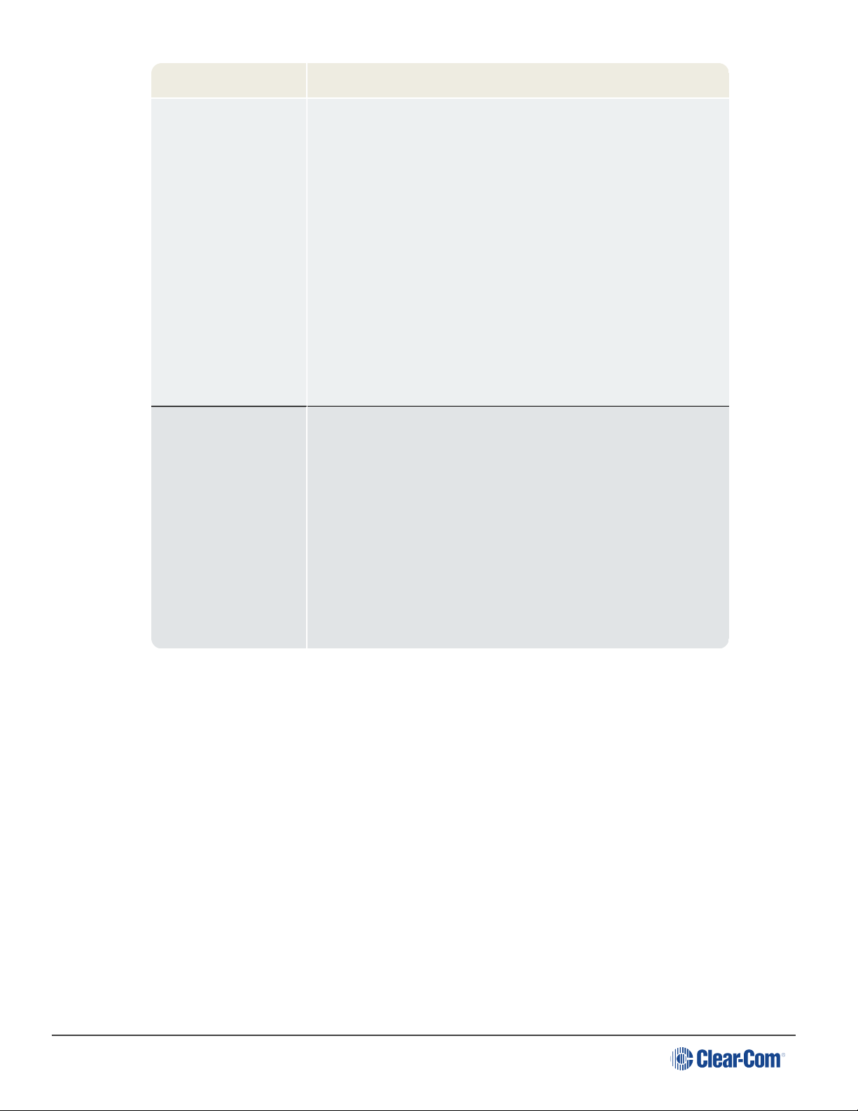
System component Connections
External computer
(PC) for EHX
The Eclipse HX configuration software runs on an external
computer (PC). The computer is normally connected to the
matrix using the LAN1 connector (a standard RJ-45 Ethernet
connector).
For Eclipse HX-Omega, Eclipse HX-Median and Eclipse HX-
PiCo, a ferrite core must be added to the socket end of each
Ethernet cable to comply with European EMC standards. A
suitable ferrite core is Würth Electronik part: 74271132.
Shielded CAT5 cable is recommended for Electro Magnetic
Compliance in EC countries.
Note: LAN1 is the default connector on the matrix. The LAN2
connector (which is also a standard RJ-45 Ethernet
connector) is unconfigured when it leaves the factory and
must be enabled in EHX before it can be used.
Tip: Connecting through an Ethernet network enables one or
more matrices to be controlled through one or more
computers on a network. You can also use the supplied DB-9
cable or a commercially available shielded RS-232 cable.
For more information, see Connecting the Matrix to a PC
Running EHX.
Note: The Eclipse HX-Pico uses a special null modem DB9
to 3.5 TRS. The HX-Median / HX-Omega /HX-Delta CPU
card uses a straight serial cable.
If the EHX computer does not have a serial port, but only
provides USB connectors, adapters are available from
computer parts suppliers. However, you will be required to
install drivers for USB-to-serial port connections.
Important note: Because of compatibility issues with some
products, Clear-Com does not recommend the use of USB-
to-serial port connections.
Page 9

User Guide | FreeSpeak Edge
System component Connections
User panels (V-
Series, I-Series user
panels and 2X10
Touch Desktop
panel)
An analog connection, using shielded CAT5 4-twisted pair
cables with RJ-45 connectors, is the most common way of
connecting V-Series user panels and I-Series panels to the
matrix.
You can use the following alternative methods for connecting
V-Series panels:
A digital connection, using the AES-6 digital interface
module. Coaxial cable is required to connect panels to the
AES-6CX rear card.
An IP-based connection, using the IVC-32 interface card
(fitted to an HX-Median, HX-Omega or HX-Delta matrix). The
IVC-32 interface card allows the Eclipse HX matrix to
connect to IP enabled V-Series panels over existing WAN /
LAN Ethernet cabling infrastructure. V-Series panels can
also optionally support up to two additional IP channels. For
more information, see the V-Series Panel User Guide.
The IVC-32 card can add IP connections through an
Ethernet switch / router linked to the Ethernet network. For
more information about the IVC-32 card, see the Eclipse
HX-Omega, Eclipse HX-Median or Eclipse HX-Delta
User Guide.
Note: For each user panel, additional connector wiring may
be required, depending on the options and accessories
installed. See Wiring System Components and the user
manual for your panel.
Page 10
User Guide | FreeSpeak Edge
System component Connections
Interface modules Interface modules are connected to the matrix using:
lParticular wiring schemes (for each module type) on
the DB-9 connectors on the rear of the associated
interface frame (IMF-3).
lShielded CAT5 4-twisted pair cables with RJ-45
connectors.
The RLY-6 and GPI-6 interface modules are connected
directly using an RJ-45 connector on the rear of the matrix
to the appropriate interface input connector on the interface
frame (IMF-3).
For more information, see Connecting to Interface Modules.
External alarm Eclipse HX matrices have built-in fault alarm systems.
If you want to use an additional remote alarm, relay contacts
are available on the rear panel of the matrix.
If you want to add an external alarm condition to the matrix
alarm system, the same connector on the rear panel alarm
I/O will permit an external contact closure to be connected to
the matrix alarm system.
Shielded cable is recommended for Electro Magnetic
Compliance in EC countries.
Note: For more information about RJ-45 connectors and their installation, see Locating
System Components.
For detailed information about wiring schemes, see Wiring System Components.
For more detailed information about the range of interface cards that can be installed to 6RU
matrices, see the:
lEclipse HX-Omega User Guide.
lEclipse HX-Median User Guide.
lEclipse HX-Delta User Guide.
Page 11

User Guide | FreeSpeak Edge
2.2 Installing the Eclipse HX System
2.2.1 Installing the Matrix in a 19” Rack
Install the matrix in a standard Electronics Industry Association 19-inch wide (48.26 cm)
equipment rack. Clear-Com recommends installing the matrix to the center portion of the rack,
allowing easy access to the connectors on the rear of the matrix.
Because of the large number of cables connected to the matrix, you should also plan for the
dressing of cables.
Environmental information
The matrix requires adequate ventilation. Leave at least 2 inches (50.8 mm) of clearance on all
sides of the matrix to ensure proper airflow. Do not block ventilation vents.
Check the position of the circuit cards (CPU cards and interface cards), power supplies, and
rear connector panels.
Note: For detailed information about installing a particular matrix or interface frame in the
rack, see the appropriate guide in the Eclipse HX documentation set. For matrices,
see the:
lEclipse HX-Omega User Guide.
lEclipse HX-Median User Guide.
lEclipse HX-Delta User Guide.
lEclipse HX-PiCo User Guide.
For interface frames, see your IMF-3 or IMF-102 documentation.
2.2.2 System Limits
The following limits apply when installing cards in an Omega, Median or Delta matrix:
lIVC-32, E-Que and LMC-64 cards are high-power devices, and you can only install a total
of four of these cards in an Eclipse Median or Delta frame. If more high-power cards are
installed, the CPU only services the first four cards (based on lower slot numbers). In this
case, a warning message is sent to the event log every 10 minutes.
lIn an Eclipse Omega frame that is fitted with a Power-One PSU, you can install up to a
total of six high-power cards. In this case, you are recommended to install a fan tray.
However, you cannot install more than four antenna/splitter E-Que cards, or more than
four E-Que cards with EM Signalling enabled. For more information about the Power-One
PSU, including part number see the Power Supplies section in the Eclipse HX Omega
User Guide.
This is summarized in the table below:
Page 12
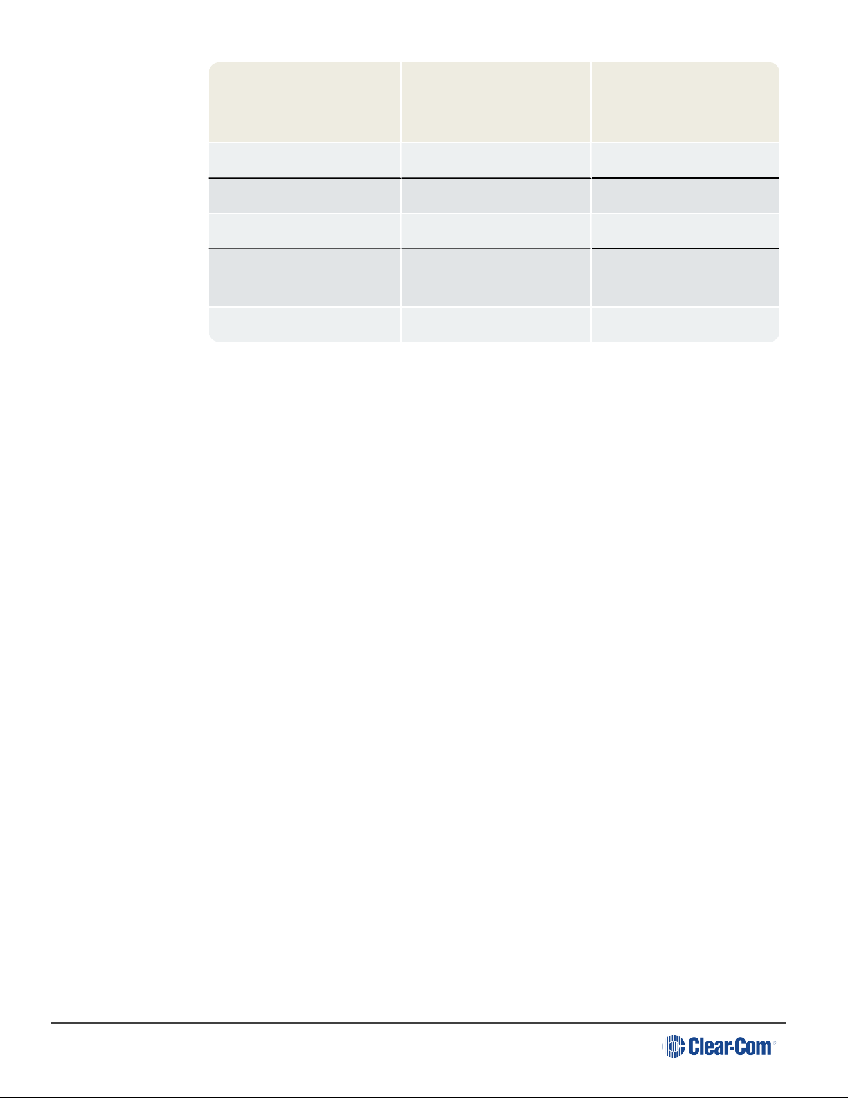
User Guide | FreeSpeak Edge
Card Maximum number with
Power-One PSU
(720379Z)
Maximum number with
other PSU
IVC-32 6 4
LMC-64 6 4
E-Que antenna/splitter 4 4
E-Que with EM signalling
enabled
4 4
E-Que other 6 4
If you attempt to add a high-power card to a matrix that already has the maximum number
installed, a warning displays in EHX software.
2.2.3 Installing the Cabling
Install the intercom cables between the Eclipse HX matrix and the other system components
(user panels and interface frames).
Clear-Com recommends that you route cables before wiring the connectors to the cables.
Note: For more information about routing cables, see Locating System Components.
2.2.4 Connecting the Other System Components to the Matrix
Connect the system components / devices (such as the external computer for EHX, interface
frames and modules, and external alarms) to the matrix.
For a wiring scheme / connection overview, see Determine Cabling and Wiring Scheme
Requirements.
Note: For detailed information about wiring schemes, see Wiring System Components.
2.2.5 Connecting to Mains AC Power
Eclipse HX matrices and interface frames (IMF-3)
Eclipse HX matrices have two separate AC power connectors for two separate power supplies
in the system. Either power supply will completely power a system, providing 100% power
redundancy. If the two power supplies are connected to different AC power sources and one of
the power supplies loses power, the other will continue to operate the system.
AC voltage for the matrices and the PSU-101 can be 100 - 240 VAC without any switching or
fuse changes.
Page 13

User Guide | FreeSpeak Edge
Each component of the Eclipse HX system requires AC power except for the IMF-3 and some
interface modules. The IMF-3 requires an external power supply. The XP-type expansion
panels receive power from the panels to which they are connected.
If you are installing an IMF-3, install the DC power cables that connect the power supply to the
matrix. For the matrix and each connected component, install and connect the mains AC power
cables.
Note: For further information, see Powering System Components.
V-Series panels
Each V-Series panel has an external power supply and a removable cradle to hold the external
power supply.
AC voltage for these panels can be 100 - 240 VAC without any switching or fuse changes.
I-Series panels
I-Series panels have internal power supplies, with removable AC power cords. The power
supplies are universal, operating over a voltage range of 90 - 245 VAC and 50 - 60 Hz. The
maximum dissipation is 40 W.
2X10 Touch Desktop panel)
The 2X10 Touch Desktop panel has a 2.5mm Power jack connector with screwlock retention to
accept the required input power of 12VDC, 2A.
An AC/DC Desk Top Power Adapter is supplied with the unit. The power adapter has the
following specification:
lInput connector : IEC-320 C14 male receptacle
lInput AC Voltage range : 100-240VAC
lInput Frequency range : 50-60Hz
lInput current : 1.2A
lOutput DC Voltage : 12VDC
lOutput rated current : 3.5A
lOutput connection : 2.5mm DC power plug ( with 1.5meters lead )
Note: Each panel must be plugged into an AC source at its location.
Page 14

User Guide | FreeSpeak Edge
Only connect power supply to earthed supply sockets. Ensure that
the power supply is routed to avoid sharp bends, hot surfaces,
pinches and abrasion. Refer all servicing to qualified service
personnel.
For more safety guidance, see the Safety Instructions supplied with
this product.
2.3 After Installing the Eclipse HX System
2.3.1 Configuring the system with EHX software
The Eclipse HX (EHX) configuration software controls the operation of the connected audio
devices by sending signals to the CPU and interface cards in the matrix, which then relay the
signals to connected audio devices and systems.
Configurations (the operating parameters of complete system setups) are created in EHX.
Up to four complete system configurations can be stored in the CPU card of the Eclipse HX-
Median, Eclipse HX-Omega, Eclipse HX-Delta or the CPU of the HX-PiCO. These
configurations can be retrieved and activated on the matrix when required.
The external PC that hosts the EHX software can store an almost unlimited number of complete
system configurations (the number is only limited by the available memory space on the PC).
You can download the configurations to the matrix as required.
When running EHX on Windows operating systems, the client and server can run on separate
machines connected over a network. You can use EHX to perform a wide range of configuration
tasks, including:
lAssigning labels (names) to ports and user panels.
lCreating point-to-point and fixed group (partyline) communications between connected
audio devices.
lEnabling, limiting or disabling features of any connected user panel or card.
lConfiguring connections between matrices.
Note: The above list is not definitive. For more information about the capabilities of EHX, see
EHX Help.
2.3.2 Minimum PC Requirements (for EHX Software)
Specification Description / Value
Processor 1 GHz
Page 15

User Guide | FreeSpeak Edge
Specification Description / Value
Memory 1GB RAM
Hard disk 1GB minimum 32 bit, 2GB minimum 64 bit.
Input devices CD-ROM drive
Display resolution SVGA
User entry Keyboard, Mouse
Ports 2 serial ports and/or network IEEE 802.3 Ethernet card
Network IEEE 802.3 Ethernet card
Operating systems EHX 8.5.1 runs on the following versions of Windows:
Microsoft Windows 7 (32-bit and 64-bit).
Microsoft Windows 8.1 (32-bit and 64-bit).
Microsoft Windows 10 (32-bit and 64-bit).
Microsoft Windows Server 2008 R2 (64-bit).
Microsoft Windows Server 2012 R2 (64-bit).
Operation on other platforms is no longer supported.
2.3.3 Recommended PC Requirements (for EHX Software)
Specification Description / Value
Processor 2GHz or greater for a client.
As many cores as possible for a server.
Memory 2GB for client 32 bit.
4GB for client 64 bit.
3GB for server 32 bit.
4GB+ for server 64 bit.
Free space 1GB minimum 32 bit.
2GB minimum 64 bit.
Display resolution 1600 x 1200
Page 16

User Guide | FreeSpeak Edge
Specification Description / Value
Operating systems EHX 8.5.1 runs on the following versions of Windows:
Microsoft Windows 7 (32-bit and 64-bit).
Microsoft Windows 8.1 (32-bit and 64-bit).
Microsoft Windows 10 (32-bit and 64-bit).
Microsoft Windows Server 2008 R2 (64-bit).
Microsoft Windows Server 2012 R2 (64-bit).
Operation on other platforms is no longer supported.
2.3.4 Checking the Installed System
After configuring the Eclipse HX system, check that every system component is functioning
correctly, including all:
lControl inputs, outputs and audio paths.
lConnections with connected external devices, such as interface modules and User
Panels
lSoftware functions, such as partylines, ISO and IFB functionality.
To assist with testing, the Eclipse HX system is delivered with a fully functional default EHX
configuration. You can tailor the configuration, using EHX software, to meet the requirements of
your particular installation.
Note: Because each installation is different, it is beyond the scope of this guide to outline in
detail all the checks that you must carry out.
Checking the matrix
Eclipse HX-Omega, HX-Median and HX-Delta
The LEDs on the front of the CPU card indicate its operational status:
Page 17

User Guide | FreeSpeak Edge
Page 18

User Guide | FreeSpeak Edge
Note: For more information about the lights and controls on the CPU card, see either.
lThe Eclipse HX-Omega User Guide.
lThe Eclipse HX-Median User Guide.
lThe Eclipse HX-Delta User Guide
Eclipse HX-PiCo
The LEDs on the front of the matrix indicate its operational status:
Note: For more information about the lights and controls on the front of the Eclipse HX-PiCo, see the
Eclipse HX-PiCo User Guide.
Page 19

User Guide | FreeSpeak Edge
3 Locating System Components
This section provides help with deploying (locating and arranging) the principal components of
your Eclipse HX system, including:
lEclipse HX matrices (Eclipse HX-Omega, Eclipse HX-Median, Eclipse HX-Delta and
Eclipse HX-PiCo).
lAn external computer (for the EHX configuration software).
lInterface frame(s) (the IMF-3 and IMF-102), which host interface modules.
lUser panels (V-Series, I-Series or 2X10 Touch Desktop panels).
lPower supplies.
Note: For an overview of the entire installation process, see Installation Overview.
3.1 Locating Eclipse HX Matrices
The Eclipse HX matrices comprise the 6RU Eclipse HX-Omega and Eclipse HX-Median, the
3RU Eclipse HX-Delta and the 1RU Eclipse HX-PiCo.
The Eclipse HX matrix is the central connecting point of the system. All other devices are
connected, either directly or indirectly, to the matrix, and this central role must be accounted for
in your deployment planning and cabling topography.
To allow easy access to connectors, ensure that you install the matrix to a central position in the
standard Electronics Industry Association 19-inch wide (48.26 cm) rack. Because of the
potentially large number of cables that may be connected to the matrix, some planning may also
be necessary for dressing the cables.
Note: A rack unit (1RU) refers to a standardized unit of space in an Electronics Industry
Association equipment rack. One rack unit is 1.75 inches high and 19 inches wide
(44.45 mm by 482.6 mm). Each increasing rack unit (1RU) adds 1h.75 inches to the
area vertically, while staying at 19 inches horizontally.
3.1.1 Locating the Eclipse HX-Omega, Eclipse HX-Median and Eclipse HX-Delta
The Eclipse HX-Omega and Eclipse HX-Median matrices each require six vertical rack units
(6RU) (10.5 inches or 267 mm) in a standard Electronics Industry Association 19-inch wide
(48.26 cm) rack. The Eclipse HX-Delta matrix requires three vertical rack units (3RU) (5.25
inches or 134 mm) in the same 19-inch rack.
Cooling the Omega / Median matrix
Each matrix has two power supplies (one for redundancy). A modular removable
alarm module fitted beneath the two power supplies has two fans that deliver
Page 20
Table of contents
Other Clear-Com Recording Equipment manuals

Clear-Com
Clear-Com CCI-22 User manual

Clear-Com
Clear-Com Eclipse IFB-104 User manual

Clear-Com
Clear-Com LQ series User manual

Clear-Com
Clear-Com PL-PRO EF-1M User manual

Clear-Com
Clear-Com ECLIPSE AES-6 User manual

Clear-Com
Clear-Com FOR-22 User manual

Clear-Com
Clear-Com LQ series User manual

Clear-Com
Clear-Com Encore TW-47 User manual

Clear-Com
Clear-Com ECLIPSE MATRIX User manual

Clear-Com
Clear-Com FIM-108 User manual


