Clearfield FieldShield YOURx-Terminal User manual

FieldShield YOURx-Terminal
Installation Manual ______________________________________________________
Manual 018994 REV B - Jan 2023
Cleareld College Product Training
Cleareld’s Certied Partnership Training Program (CPTP) is open to customers and
contractors with the desire to become a Cleareld partner.
SIGN UP TODAY to learn the proper installation techniques for Cleareld products.
It’s FREE!!
www.seecleareld.com/training/cleareld-college/certied-partnership-training.html
Are you?
CLEARFIELD
CERTIFIED

Direct: 763.476.6866 • National: 800.422.2537 • www.SeeCleareld.com • techsupport@seecleareld.com
2
FieldShield YOURx-Terminal
Installation Manual _________________________________________________________
Manual 018994 REV B - Jan 2023
Table of Contents
Parts List 3
Recommended Tools 4
Opening the Cover 6
Drop Terminal Congurations 7
Port Designations 8
Deploying Patch-Only Congurations 9
Pole/Wall Mounting 10
Pedestal Mounting 11
Strand Mounting 12
Vault Installation 13
Site Preparation 13
Preparing Terminal Ports 15
Installing FlexPorts in the Field 15
Plugs 16
Preparing Microduct to Connect to Terminal 16
Installation of Fiber 17
Field Installable FlexConnector 20
Field Installable FlexConnector 21
Closing the YOURx-Terminal 23
Connector Cleaning Procedure 24
Standard Warranty 29
Proprietary Notice 30
Technical Support 30
3
FieldShield YOURx-Terminal
__________________________________________________________ Installation Manual
Direct: 763.476.6866 • National: 800.422.2537 • www.SeeCleareld.com • techsupport@seecleareld.com
Manual 018994 REV B - Jan 2023
2
6
3
7
9
1
4
5
6
8
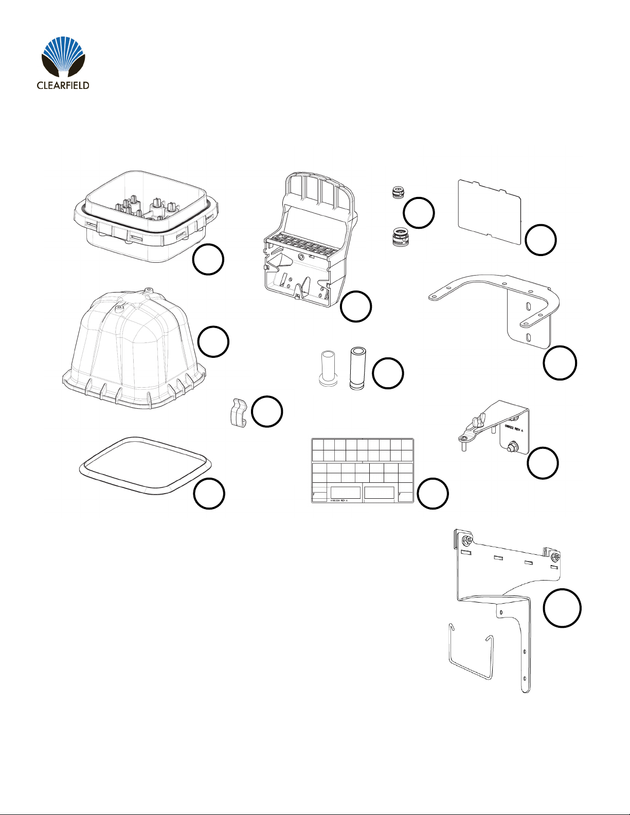
1. Base (FlexPort Sealing Tabs marked with a silver “x” inside the terminal)
2. Cover
3. Gasket
4. Clips (8 installed on base)
5. FlexCartridge
6. FlexPort ½ (half) Cartridge
7. Plugs (available 10mm and 14mm)
8. Designation Card
9. FlexCartridge Cover
10. Base Mounting Bracket*
11. Cover Mounting Bracket*
12. Aerial Strand Bracket*
*Ordered Seperately (not included with terminal)
10
12
11
Parts List
Direct: 763.476.6866 • National: 800.422.2537 • www.SeeCleareld.com • techsupport@seecleareld.com
4
FieldShield YOURx-Terminal
Installation Manual _________________________________________________________
Manual 018994 REV B - Jan 2023
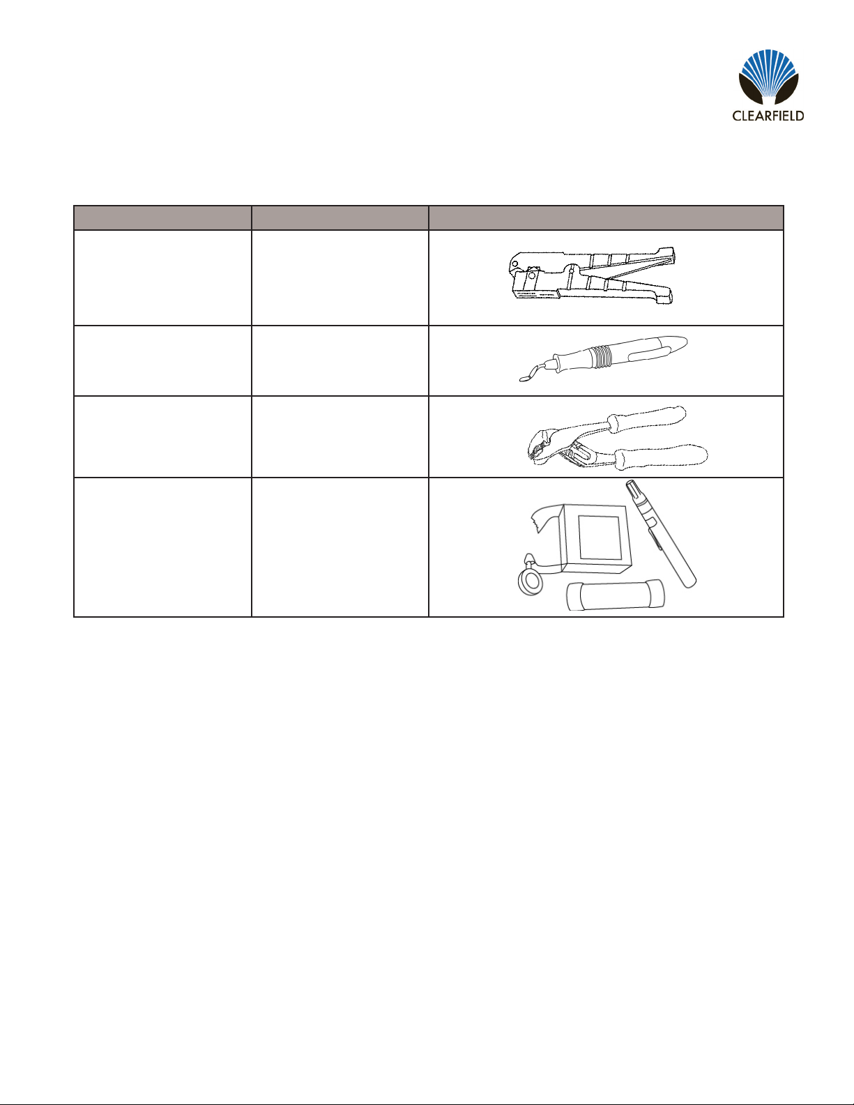
Find No. Tool Image
001 Rotary Cutter
002 Deburring Tool
003 Pliers
004 Optical End Face
Cleaning kit
Recommended Tools

5
FieldShield YOURx-Terminal
__________________________________________________________ Installation Manual
Direct: 763.476.6866 • National: 800.422.2537 • www.SeeCleareld.com • techsupport@seecleareld.com
Manual 018994 REV B - Jan 2023
Product
Name
Cable
Jacket UV Temperature FieldShield
Connector
Jacket
Color
Can be
stapled
Best
Application
FieldShield
FLATdrop
Outdoor Yes -40° to 176°F No Black Yes
For use when fast installation
and low up-front cost is most
desired feature.
Field Installable
FlexConnector Optional
FieldShield
(Classic)
Outdoor
in Duct
Yes in
Duct -40° to 176°F Yes Black Yes
For use when the distance
from the access point to the
SFU/MDU is longer than
normal and a more rigid solu-
tion is required to maintain
restorability for drops longer
than 300 feet.
Field Installable
FlexConnector Optional
FieldShield
FLEXdrop
Indoor
(Plenum)/
Outdoor
Yes -40° to 176°F Yes Black/
White Yes
For use when a premium
product that has maximum
workability, exibility and
restorability is desired.
FieldShield
StrongFiber Indoor/
Outdoor
in Duct
Yes in
Duct -40° to 176°F Yes Black Yes in
Duct
For use when a reusable
pathway is needed and
maximum slack storage is
desirable.
DROP CABLE OPTIONS
Direct: 763.476.6866 • National: 800.422.2537 • www.SeeCleareld.com • techsupport@seecleareld.com
6
FieldShield YOURx-Terminal
Installation Manual _________________________________________________________
Manual 018994 REV B - Jan 2023
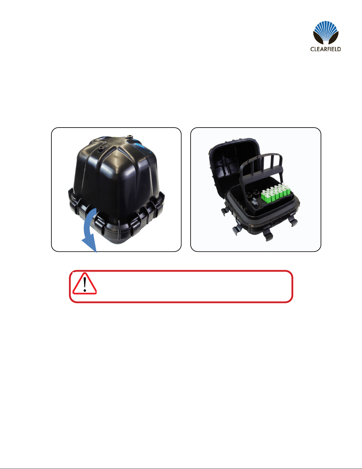
Opening the Cover
To open the FieldShield YOURx-Terminal, release the lid by pulling the 8 tabs down from the cover towards the base. Then
pull off the lid.
Note:The lid may be difcult to remove due to gasket sealing.
DO NOT use a sharp item (snips, screwdriver, etc.) to remove.
Utilize a stiff at piece of plastic, like a wedge, to help break the seal.
Using the sharp items may damage the gasket.
IMPORTANT
7
FieldShield YOURx-Terminal
__________________________________________________________ Installation Manual
Direct: 763.476.6866 • National: 800.422.2537 • www.SeeCleareld.com • techsupport@seecleareld.com
Manual 018994 REV B - Jan 2023
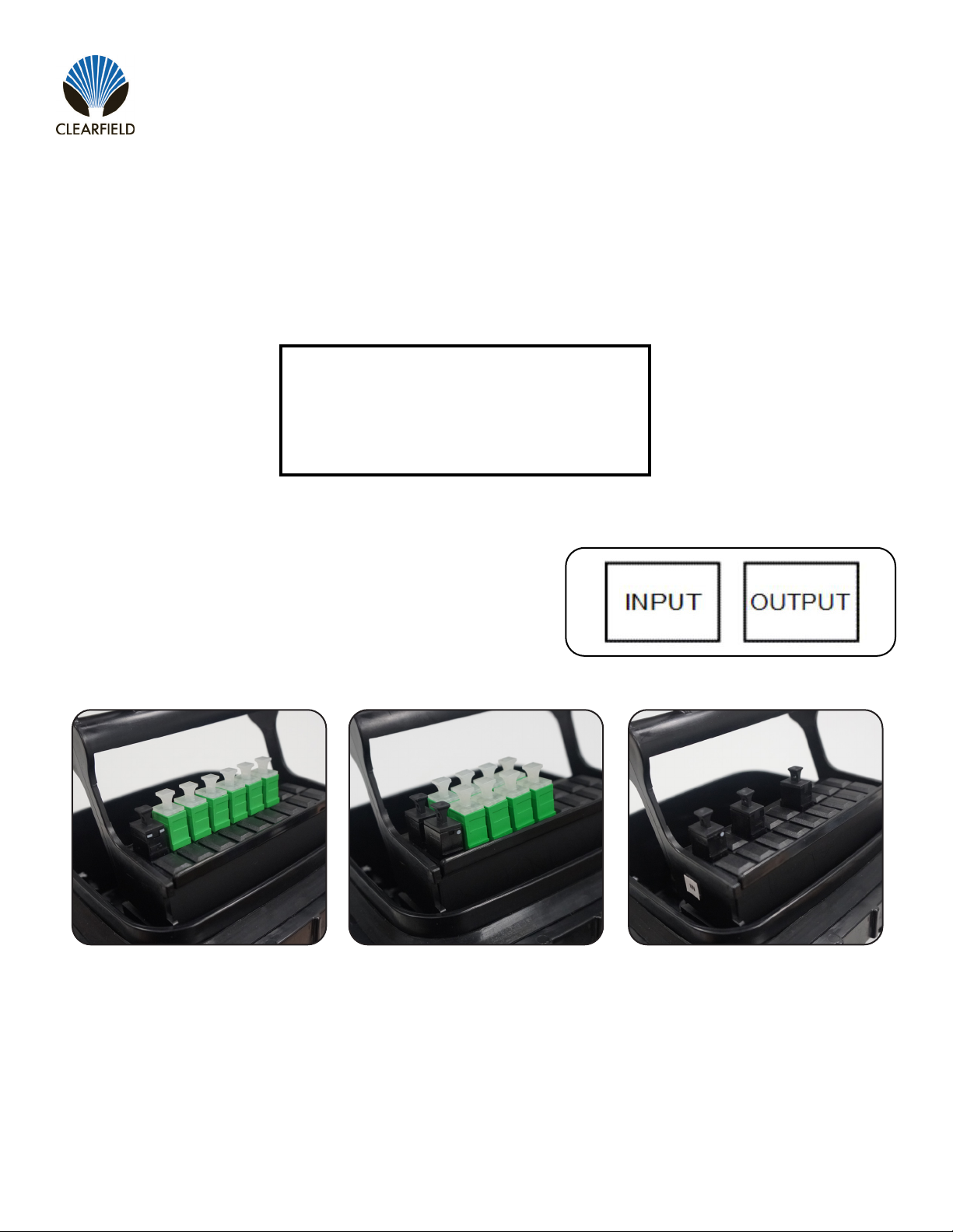
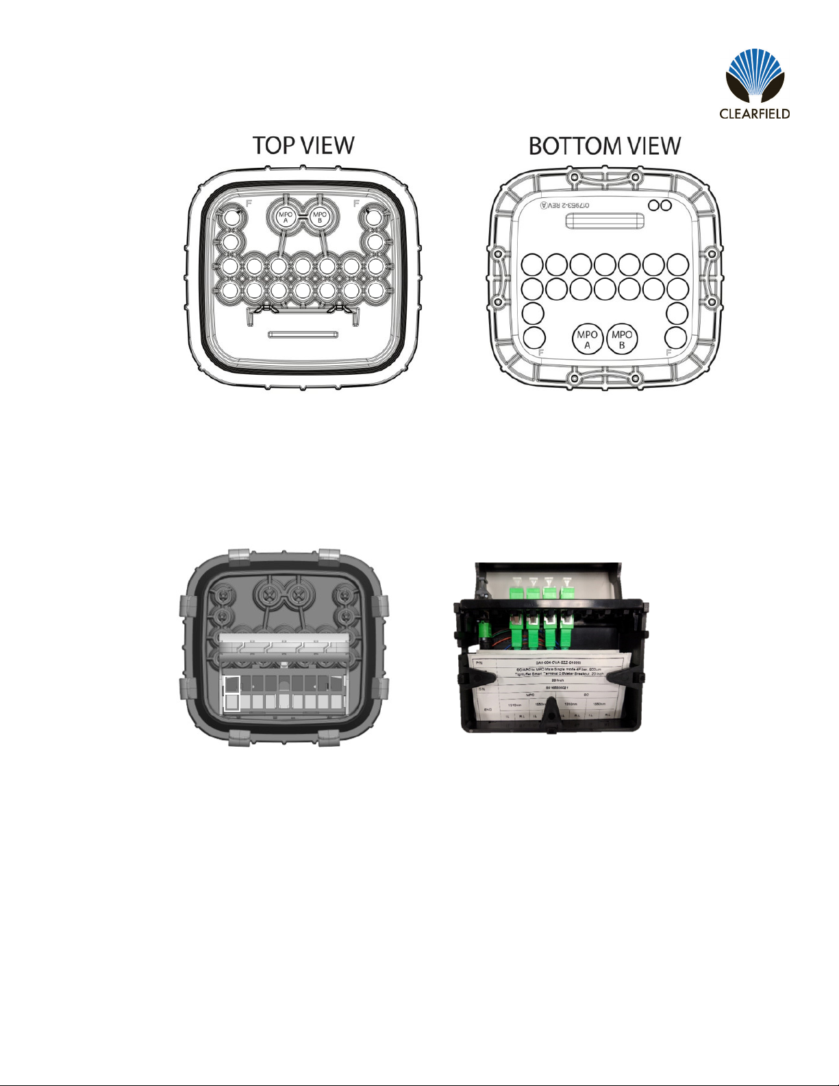
• “Drop only” where there is a choice of one 14mm or one 10mm port used for feed (MPO input) and designated
number of ports for distribution (Figure 1).
• “Drop and Express” congured terminals will utilize both “A and B” ports for feed (MPO input) to terminal with
expressing (MPO output) the un-used bers to the next terminal in line (Figure 2).
• “Branch” congured terminal utlizing 3 MPO’s, a single feed MPO to two MPO outputs.
Drop Terminal Congurations
Note: These are “standard” congurations, your terminal may be unique to your environment.
Remember: SC/LC/MPO ports on FlexCartridge are opposite of labeling in base to minimize ber crossover.
Note: If terminal is being utilized with splitters, the feed may be fed through 10mm port of choice for termination
Cable Feed/Express Port Types
14mm: Microduct with pushable MPO
10mm or 14mm: FLATdrop MPO
10mm or 14mm: FLATdrop or microduct pushable
single ber for splitter feed
When expressing bers using MPOs, Input (port A) and Output (port
B) will be marked with a sticker as shown.
Drop Only Terminal Drop and Express
Terminal
Branch Terminal
Direct: 763.476.6866 • National: 800.422.2537 • www.SeeCleareld.com • techsupport@seecleareld.com
8
FieldShield YOURx-Terminal
Installation Manual _________________________________________________________
Manual 018994 REV B - Jan 2023
Port Designations
Ports A and B: 14mm microduct
Ports 1 thru 16: 10mm microduct
*Port C: Branch Terminal only
Note: Pushable MPO’s enter through the 14mm ports. When a third MPO is needed, you will utilize a atdrop cable with a
FlexConnector and enter through 10mm feeder port C.
FlexCartridge Designations
Port counts differ, depending on terminal designation
MPO Ports
A - Fiber “IN” (feed)
B - Fiber “OUT” (express)
C - Fiber “OUT” (Branch only)
Distribution Ports 1-16
SC, LC or MPO connectors
Test record found behind
removeable cover
1 2 3 4 5 6 7 81 2 3 4 5 6 7 8
AA
BB
1313
99
1010
1111
1212 1515 1616
1414
C
1 2 3 4 5 6 7
8 9 10 11 12 13 14
15 16
C
C
1 2 3 4 5 6 7
8 9 10 11 12 13 14
15 16
C

9
FieldShield YOURx-Terminal
__________________________________________________________ Installation Manual
Direct: 763.476.6866 • National: 800.422.2537 • www.SeeCleareld.com • techsupport@seecleareld.com
Manual 018994 REV B - Jan 2023
Deploying Patch-Only Congurations
Alternatively, you may mount the spool on a turntable (lazy susan) and de-
ploy the ber while the spool is in a horizontal orientation. Mount the spool
on the turntable with the cable on the bottom and the YOURx-Terminal on
top for stability.
Patch-Only congurations of the YOURx-Terminal will arrive packaged in a
box as shown. Remove the terminal, and the cable spool it is mounted to,
from the box.
To deploy the cable, mount the entire spool on an A-frame or similar axle,
with the shrink wrap still applied to the terminal end of the spool.
Proceed to deploying the cable following local practices.
Note: Ensure that the cable is paying off over the top of the spool and that
extra twists are not present when deploying.
Note: For aerial applications, when lashing, mount the terminal to the
strand rst, and lash towards the end of the cable
Once your cable is deployed, you may
remove the shrink wrap, discard the
cardboard spool, and proceed to mount-
ing the YOURx-Terminal.
Note: Do NOT remove red locking ring
from FlexPort of pre-installed cables.
1.
2.
3.
4.
5.

Direct: 763.476.6866 • National: 800.422.2537 • www.SeeCleareld.com • techsupport@seecleareld.com
10
FieldShield YOURx-Terminal
Installation Manual _________________________________________________________
Manual 018994 REV B - Jan 2023
Pole/Wall Mounting
Utilizing the horseshoe base mount bracket, mount the bracket to the surface (hardware not included), then mount the
YOURx-Terminal to the bracket using the provided hardware (4 provided screws) (Figure 1). Microduct will be cut to desired
length for proper storage, following local practice.
Figure 1
(4) mounting screws provided

11
FieldShield YOURx-Terminal
__________________________________________________________ Installation Manual
Direct: 763.476.6866 • National: 800.422.2537 • www.SeeCleareld.com • techsupport@seecleareld.com
Manual 018994 REV B - Jan 2023
Pedestal Mounting
YOURx Terminal - Base Mount
Install the base mount bracket onto the YOURx Terminal rst, via the 4 screw locations. Then mount the terminal and brack-
et into the ped.
YOURx Terminal - Cover Mount
Note: The YOURx-Terminal is capable of tting into as small as an 8 X 8 pedestal but due to room restrictions we
recommend a minimum of 10 X 10.
Install the rst piece of the mounting bracket to the top of the YOURx-Terminal cover using the provided screws.

Direct: 763.476.6866 • National: 800.422.2537 • www.SeeCleareld.com • techsupport@seecleareld.com
12
FieldShield YOURx-Terminal
Installation Manual _________________________________________________________
Manual 018994 REV B - Jan 2023
Install the cover mount bracket into the pedestal. The bolt of the cover mounted bracket can be slid into the gap in the top
mounting bracket and the terminal secured in place by tightening the wing nut on the bolt.
Strand Mounting
1. Attach lanyard using provided screw, to location identied in (Figure 1).
2. Attach opposite end to location in (Figure 2).
3. Using provided hardware attach base to bracket like shown (Figure 3).
4. Attach to strand using provided bug nuts. Facing FlexPorts toward
serving pole.
5. Dress duct from pole attachment to terminal, cut duct to length.
Figure 1 Figure 2 Figure 3
13
FieldShield YOURx-Terminal
__________________________________________________________ Installation Manual
Direct: 763.476.6866 • National: 800.422.2537 • www.SeeCleareld.com • techsupport@seecleareld.com
Manual 018994 REV B - Jan 2023
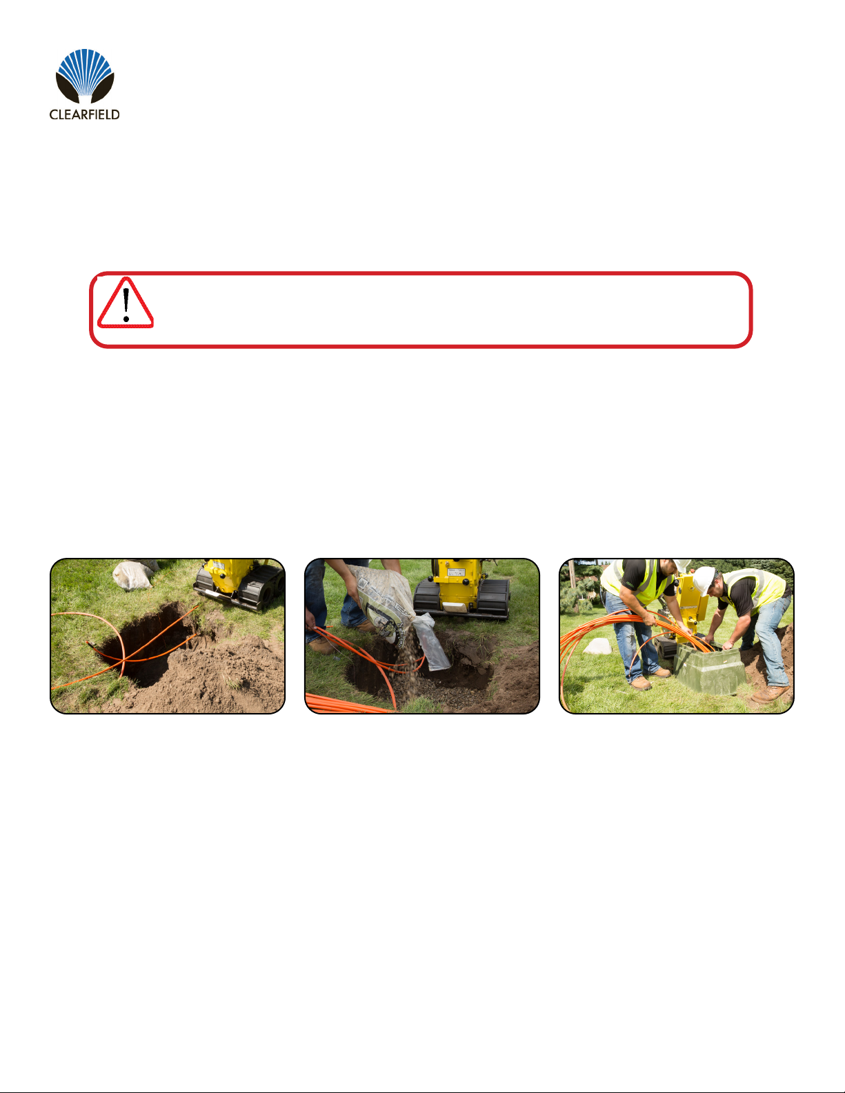
Figure 1
Step 1: Excavation
Plan excavation approximately twelve
to sixteen inches (12” - 16”) longer/
wider and six to eight inches (6” - 8”)
deeper than the actual dimensions of
the vault being installed. (Figure 1)
Site Preparation
Ensure that national – local electrical and building codes, OSHA and company safety work rules are observed and provi-
sions made for street ags, barricades and cones. Secure permits as required by city and company.
Figure 3Figure 2
Step 2: Drainage Base
Pour gravel base to a depth of three to
ve inches at (3” - 5”) the base of the
excavation. (Figure 2)
Note: Base material should be crushed
rock 3/4” and smaller, and not “river
rock” or “round stone.”
Step 3: Install Vault
Guide microduct through opening and
lower vault into excavation on top of
base material and adjust height to
grade. (Figure 3)
Vault Installation
WARNING: Buried Telecommunications Cables. Make sure to call 811 a few days before digging.
Calling 811 will route to the local one-call center and ensure that utilities in the area of installation
will be located and marked.
IMPORTANT

Direct: 763.476.6866 • National: 800.422.2537 • www.SeeCleareld.com • techsupport@seecleareld.com
14
FieldShield YOURx-Terminal
Installation Manual _________________________________________________________
Manual 018994 REV B - Jan 2023
Figure 4 Figure 6Figure 5
Step 4: Backll
Use soil to backll between the vault
and the excavation wall, tamping down
to compact soil. (Figure 4)
Step 5: Route Duct
Deterimine desired length of all ducts
entering the terminal. (Figure 5)
Note: Multiple ducts should be bound
together with vinyl tape for easier
manipulation.
Step 6: Prepare Duct
Use a rotary cutting tool to all ducts to
equal length. Strip back outer sheath
and tone wire six inches (6”) or
amount needed to terminate to bond/
locating bar. Use de-burring tool to
chamfer end of duct. (Figure 6)
Figure 7 Figure 8
Step 7: Prepare Ports
Remove tabs from desired terminal
FlexPorts. De-burr FlexPort with snips,
knife or de-burring tool to remove
rough edges. MUST de-burr entirely
for FLATdrop MPO bullet to t through
port. (Figure 7)
Step 8: Seat Duct
Feed pull string from the underside of
the terminal through port and seat duct
fully into the coupler. (Figure 8)
Step 9: Secure Pull String
Tie off pull string to FlexCartridge to
prevent it from migrating back into the
microduct.
Note: Ports loaded with exports are
marked in silver.
15
FieldShield YOURx-Terminal
__________________________________________________________ Installation Manual
Direct: 763.476.6866 • National: 800.422.2537 • www.SeeCleareld.com • techsupport@seecleareld.com
Manual 018994 REV B - Jan 2023
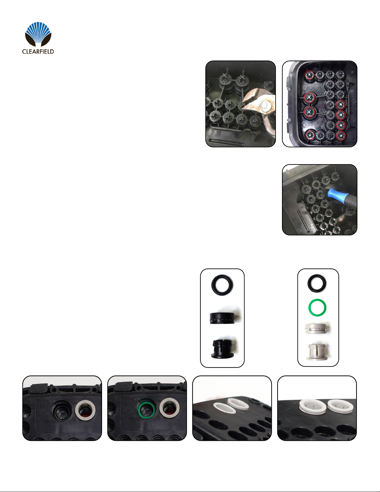
Preparing Terminal Ports
When needed for congurability, FlexPorts can be added in
the eld to allow the terminal to accept additional ber drops,
microduct or other options, when desired for a change needed.
Step 1: Locate and using pliers, remove tab associated to
the 10mm or 14mm port that you will use. (Figure 1)
Note: Ports with factory installed FlexPorts will be marked
with a silver X (Figure 2).
Step 2: De-Burr (using a de-burring tool/snips/knife) the
port hole for a smooth transition without damaging the ber
as it enters the port (Figure 3). Must be fully de-burred for
FLATdrop MPO.
Figure 1
Figure 3
1. On bottom of terminal, place O-Ring into desired port hole
2. If installing a 14mm, place “Green Spacer” on top of
O-Ring
3. Next, place “Press-In” with teeth closest to you, into hole.
Tap in so that it sits ush.
4. Install the “Clip” into the “Press-In”
Note: Clips should be loose, not springy. If springy, re-adjust
the O-Ring.
O-Ring
Green Spacer
Press-in
Clip
BE AWARE! FlexPorts are factory installed on units that come from the factory
based on the number of feed and distribution specied at time of order.
Following the diagram, place parts as shown below.
Installing FlexPorts in the Field
Figure 2
Direct: 763.476.6866 • National: 800.422.2537 • www.SeeCleareld.com • techsupport@seecleareld.com
16
FieldShield YOURx-Terminal
Installation Manual _________________________________________________________
Manual 018994 REV B - Jan 2023
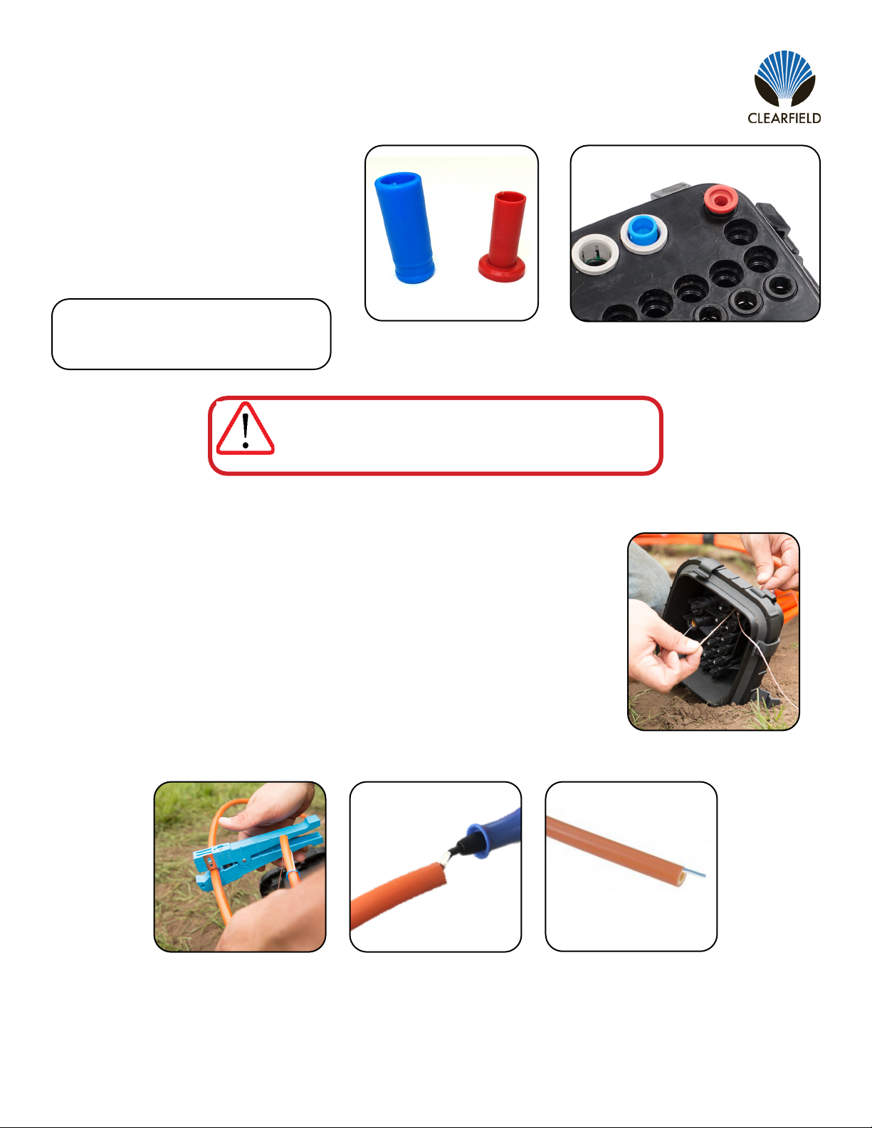
Plugs
If a technician removes the wrong tab and
exposes a port WITHOUT a FlexPort, the port
CANNOT be sealed with a plug (Figure 1)
WITHOUT a FlexPort installed (Figure 2). For
a water and air-tight seal, install FlexPort prior
to inserting plug.
WARNING: Do NOT Leave terminal ports open.
Always use a 10mm or 14 mm plug.
IMPORTANT
Note: (1) 10mm included with terminal
10mm: 018432
14mm: 018665
Figure 1 Figure 2
Preparing Microduct to Connect to Terminal
Step 1: Feed “pull string” through FlexPort. (Figure 3) If not pulling ber immediately, tie
off to FlexCartridge.
Step 2: Using a rotary cutter to prevent cutting pull string, make a ush cut at desired
length (Figure 4) and de-burr microduct (Figure 5).
Note: When using toneable microduct, remove outer sheath and tone wire back
approximatel 4”-6” (follow local standard as to storing tone wire) (Figure 6).
Figure 3
Figure 4 Figure 5 Figure 6

17
FieldShield YOURx-Terminal
__________________________________________________________ Installation Manual
Direct: 763.476.6866 • National: 800.422.2537 • www.SeeCleareld.com • techsupport@seecleareld.com
Manual 018994 REV B - Jan 2023
Installation of Fiber
When entering the YOURx-Terminal DO NOT assemble Connector Outer Housing until ber has been
passed through the FlexPort. Fully connectorized ber will not pass through FlexPort.
IMPORTANT
Figure 3
Figure 4
Step 3: Assemble
Connector
Follow assembly
instructions for the
selected connector.
(Figure 3).
Step 4: Connect Fiber into FlexCartridge
Once connector has been inspected/cleaned, route
ber through ber management located in the
“handle” of the FlexCartridge. Make the connection.
(Figure 4).
Figure 1
Step 2: Pull Fiber
Pull preconnectorized
ber (unassembled) into
open YOURx-Terminal
port. Remove pull string
and prepare connector
for assembly.
(Figure 2).
Step 1: Seat
Microduct
Once Pull String is
through the FlexPort, seat
Microduct into FlexPort.
(Figure 1).
Figure 2
FieldShield FLEXdrop or FieldShield
INSPECT BEFORE YOU CONNECT!
CLEAN CONNECTOR DIRTY CONNECTOR
SEE RECOMMENDED CLEANING PROCEDURES SECTION

Direct: 763.476.6866 • National: 800.422.2537 • www.SeeCleareld.com • techsupport@seecleareld.com
18
FieldShield YOURx-Terminal
Installation Manual _________________________________________________________
Manual 018994 REV B - Jan 2023
FieldShield StrongFiber
Figure 3
Figure 4
Step 3: Assemble
Connector
Follow assembly
instructions for the
selected connector.
(Figure 3).
Step 4: Connect Fiber into FlexCartridge
Once connector has been inspected/cleaned, route
ber through ber management located in the
“handle” of the FlexCartridge. Make the connection.
(Figure 4).
Figure 1
Step 2: Pull Fiber
Pull preconnectorized
ber (unassembled) into
open YOURx-Terminal
port. Remove pull string
and prepare connector
for assembly.
(Figure 2).
Step 1: Seat
Microduct
Once Pull String is
through the FlexPort, seat
Microduct into FlexPort.
(Figure 1).
Figure 2
INSPECT BEFORE YOU CONNECT!
CLEAN CONNECTOR DIRTY CONNECTOR
SEE RECOMMENDED CLEANING PROCEDURES SECTION

19
FieldShield YOURx-Terminal
__________________________________________________________ Installation Manual
Direct: 763.476.6866 • National: 800.422.2537 • www.SeeCleareld.com • techsupport@seecleareld.com
Manual 018994 REV B - Jan 2023
Figure 1 Figure 2
FieldShield FLATdrop
Step 1: Push Fiber
Push preconnectorized
ber (unassembled) into
open YOURx-Terminal
port. Remove pull string
and prepare connector
for assembly.
(Figure 1).
Step 2: Seat
FlexConnector
Once ber is through,
seat FlexConnector into
FlexPort.
(Figure 2).
INSPECT BEFORE YOU CONNECT!
CLEAN CONNECTOR DIRTY CONNECTOR
SEE RECOMMENDED CLEANING PROCEDURES SECTION
Figure 3
Figure 4
Step 4: Connect Fiber into FlexCartridge
Once connector has been inspected/cleaned, route
ber through ber management located in the
“handle” of the FlexCartridge. Make the connection.
(Figure 4).
Step 3: Assemble
Connector
Follow assembly
instructions for the
selected connector.
(Figure 3).
Direct: 763.476.6866 • National: 800.422.2537 • www.SeeCleareld.com • techsupport@seecleareld.com
20
FieldShield YOURx-Terminal
Installation Manual _________________________________________________________
Manual 018994 REV B - Jan 2023
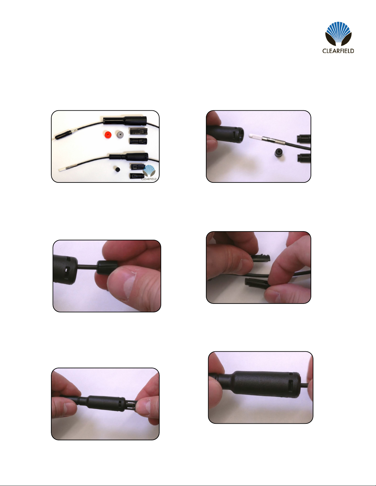
Field Installable FlexConnector
Figure 1
Step 1: Prepare Components
(Figure 1).
Figure 2
Step 2: Pass Fiber Through
FlexConnector
(Figure 2).
Figure 3
Step 3: Install Split-Seal
Select appropriate size split-seal, slide
onto ber and seat into the FlexConnec-
tor (Figure 3).
Figure 4
Step 4: Install 2 Piece Retainer
Sandwich both halves of the retainer
over the ber (Figure 4).
Figure 5
Step 5: Seat 2 Piece Retainer
Align the retainer clips with the slots of
the FlexConnector and press into place
(Figure 5).
Figure 6
Step 6: Install FlexConnector
into YOURx-Terminal
- FieldShield
Other manuals for FieldShield YOURx-Terminal
1
Table of contents
Other Clearfield Cables And Connectors manuals


