manuals.online logo
Brands
  1. Home
  2. •
  3. Brands
  4. •
  5. Radiall
  6. •
  7. Cables And Connectors
  8. •
  9. Radiall SOLYNEO CO15CAN User manual

Radiall SOLYNEO CO15CAN User manual

CO15CAN KIT
CONTACTLESS
POWER & DATA
Product Manual
SIMPLIFICATION IS OUR INNOVATION
MU343632012400
2|CO15CAN PRODUCT MANUAL
SIMPLIFICATION IS OUR INNOVATIONVisit www.radiall.com for more information
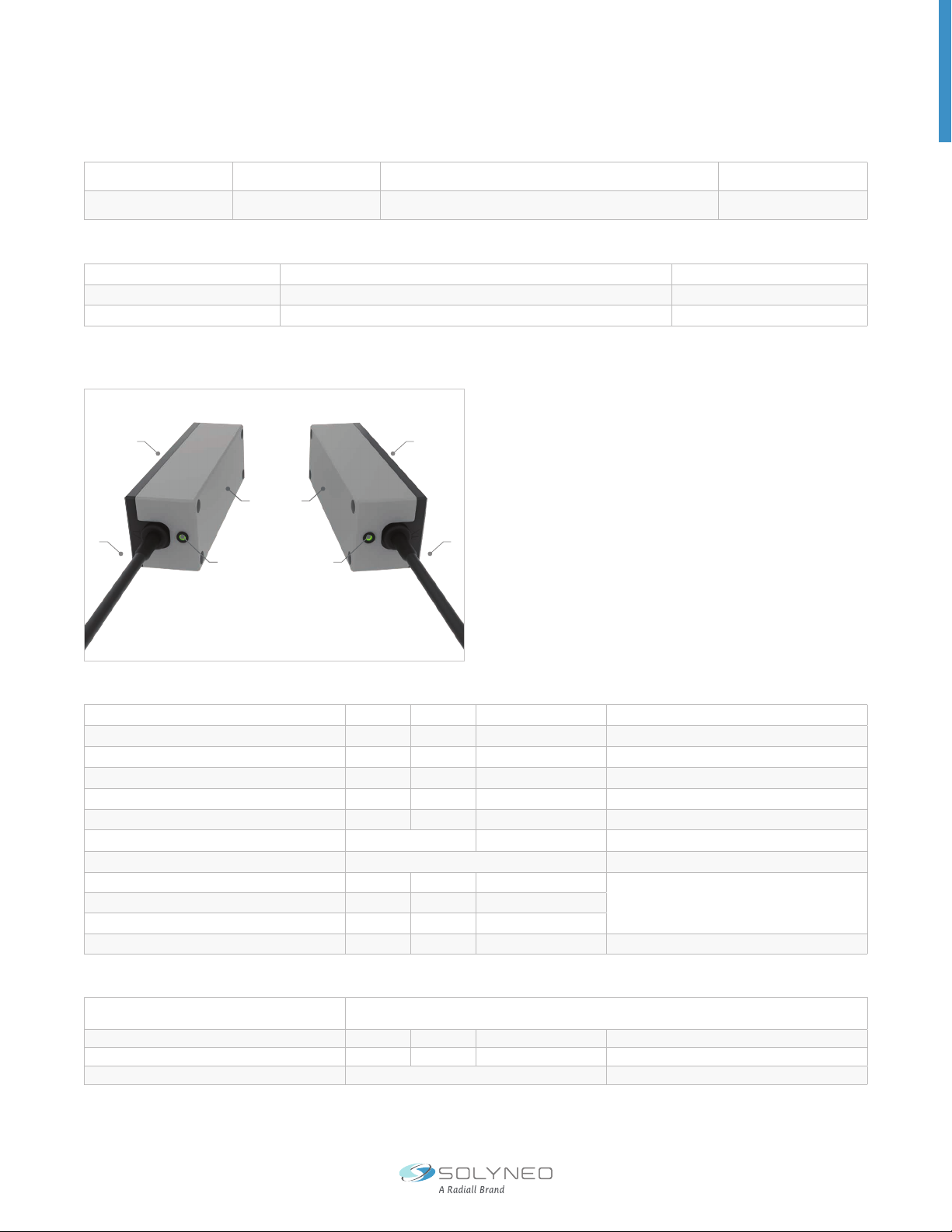
CO15CAN KIT |15W CAN CONTACTLESS
POWER & DATA
OVERVIEW
This document guides users how to use the Co15CAN
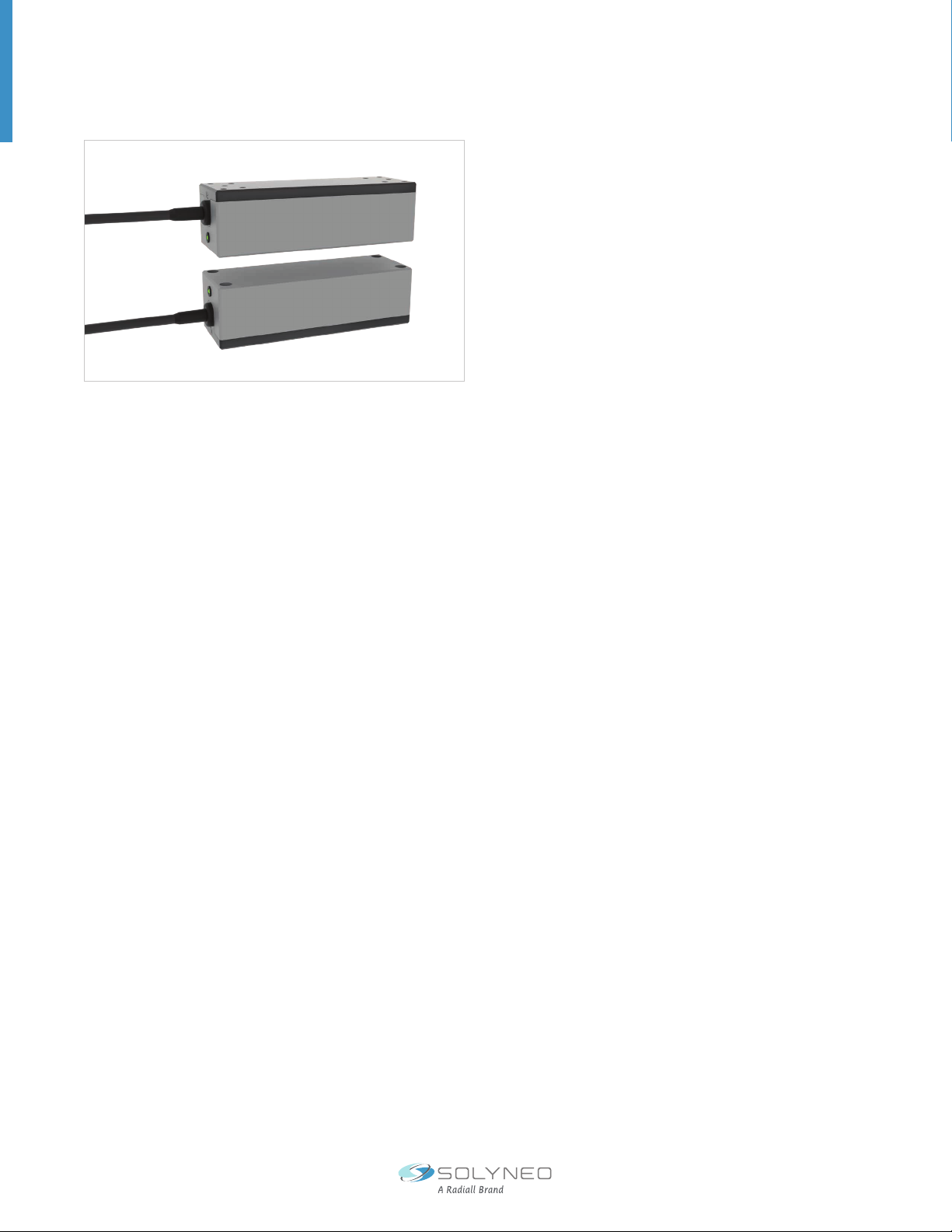
Kit. The Co15CAN Kit includes a transmitter (Tx) and
receiver (Rx). Modules Tx and Rx are inductive couplers
that supply power without physical contact power
and data transmission providing 15 W at short range
(few centimeters). The kit allows testing the benets
of contactless connectors by enabling cable limits and
design barriers for more reliability and exibility.
APPLICATIONS
Contactless connectors open a new scene for connectivity. By eliminating the needs for physical cables or connectors.
Connection for applications in constrained and/or moving environments becomes easier. This new technology nds
applications in various industrial, defense and aeronautic applications as well as in the medical eld.
For example:
• For example, when changing tools on robots, the life cycle of the connectors is limited because the connectors can
deform or break. Contactless connectors make connection more reliable and maintenance-free.
• For example, to communicate or power a system in a harsh or enclosed environment such as in a cleanroom, wired
systems with open contacts are very expensive and weaken the system. Contactless connectors make connection
more reliable by transferring through any-non electrically conducting material including gasses and liquids without
contact or need to drill a hole.
Use cases:
• Supply power through any-non electrically conducting material
• Supply power moving electronic system
• Supply power embedded electronic system
• Enable new design (transfer through sealed enclosures)
FEATURES
• 15 W continuous power transmission
• Bi-directional data transmission
• Short range contactless connectivity
• Misalignment tolerance
• Free-movement due to no decoupling
• Used in pairs (transmitter Tx and receiver Rx)
BENEFITS
• No wear and tear
• Simplify interconnection
• No wi or bluetooth interface
• No limited by mating cycle
• Free maintenance
• Providing immunity to vibration
• Providing immunity contaminants, moistures, dust
PRODUCTS |03
CO15CAN PRODUCT MANUAL |3
SIMPLIFICATION IS OUR INNOVATION Visit www.radiall.com for more information
REFERENCES
[1] Datasheet, MU343632012400 Revision 1
[2] Handout, MU343632012400 Revision 1
[3] External Presentation, MU343632012400 Revision 1
Transmitter TX MU313632012400 Freespace Contactless Power & Data Transmitter
15 W CAN 8-16 mm 24 VDC Rect. Screw 1
Receiver RX MU323630212400 Freespace Contactless Power & Data Receiver
15 W CAN 8-16 mm 24 VDC Rect. Screw 1
KIT CONTENT [1]
SPECIFICATIONS
GENERAL SPECIFICATIONS
DATA COMMUNICATIONS
TX Input Voltage 24 Vdc ± 10% -
RX Output Voltage 24 Vdc ± 5% -
Input Current Max 1.2 A - @ Output Power = 15 W
RX Output Power 15 W - @ TX Voltage = 21.6 V / Z = 16 mm / X = Y = 2 mm
Peak Power 15 W - -
Maximum Capacitive Load 47 µF - -
Eciency 84% ± 2% See Eciency Section
Operating Indication LED See LED Indicators Section
Maximum Axial Distance 16 mm -
See Air Gap & Misalignment Section
Minimum Axial Distance 8mm -
Misalignment X,Y ± 2 mm -
Operational Readiness Power 1 s - -
Protocol CAN 2.0A
CAN 2.0B
Data Rate 250 kbps - -
Latency 400 µs -Minimum Latency
Termination No 120 Ohms on Request
6
25 5
2
1
1
6
1. Transmitter (Tx)
2. Receiver (Rx)
3. Power Cable, M12 Female
4. Power Cable, M12 Male
5. Status LED
6. Cooling Fins
Notes
1. Available in sample volumes only
4|CO15CAN PRODUCT MANUAL
SIMPLIFICATION IS OUR INNOVATIONVisit www.radiall.com for more information
Size 14 x 38 x 33.5 mm -
Typ. Weight 220 g -
Cable Length 25 cm ± 5 cm
Case Aluminum Alloy
Top Cover PET
Notes
1. Tx and Rx have similar mechanical specications.
MECHANICAL SPECIFICATIONS [1]
PRODUCTS |03
CO15CAN PRODUCT MANUAL |5
SIMPLIFICATION IS OUR INNOVATION Visit www.radiall.com for more information
ENVIRONMENTAL SPECIFICATIONS
CONNECTOR PINNING
LED INDICATORS
Operating Temperature -40 to 70 ºC
Storage Temperature -55 to +85 °C
Quick Temperature Change 10 °C/Min
Protection Degree IP65
Reverse Polarity Protection of the Power Supply Yes
Short-Circuit Protection of the Power Output Yes
Short-Circuit Protection for Data Output Yes Under Conditions CAN Link: Yes
Overheating Protection Yes
Dynamic Coupling Yes
STATUS LED CODE [1] MEANING
Flashing Red, Green and O ••••••••••Searching for Rx and Tx Connection
Blink Red ••••••••••Rx Disconnected
Fast Flashing Green and Red ••••••••••Mode Binding
Fix Green •••••••••• Normal Operation
Fix Red •••••••••• Waiting for Input Voltage Higher than 21.6 Vdc
M12, Female
(A-Coded)
POS NUMBER M12 NOTES
1SHIELD Internally Connected to Main Frame
2V+ Power Supply
3V- Ground / 0V
4CAN_H CAN_H Bus Line
5CAN_L CAN_L Bus Line
M12, Male
(A-Coded)
POS NUMBER M12 NOTES
1SHIELD Internally Connected to Main Frame
2V+ Power Output
3V- Ground / 0V
4CAN_H CAN_H Bus Line
5CAN_L CAN_L Bus Line
Connector Pinning Receiver (Rx)
Industry Standard Cable Connector M12, Female, 5 Pin, A-Coded
There is a status LED on each transmitter Tx and receiver Rx.
Connector Pinning Transmitter (Tx)
Industry Standard Cable Connector M12, Male, 5 Pin, A-Coded
Notes
1. 100 ms step
6|CO15CAN PRODUCT MANUAL
SIMPLIFICATION IS OUR INNOVATIONVisit www.radiall.com for more information
AIRGAP & MISALIGNMENT
TRANSMISSION DISTANCE
MISALIGNMENT
Maximum Power Over Misalignment
Misalignment : X = 2 mm & Y = 2 mm
The system transmits contactless power at 8 to 16 mm for max power level of 15 W.
USER MANUAL | MU230341011401
Freespace Contactless Data Transceiver Ethernet 30mm 12 VDC Self-adhesive Rect. Kit 1
Information subject to change without further notice |Version 1.0|24/05/2022
9
AIRGAP AND MISALIGNMENT
The system transmits contactless power at 8 to 16mm for max power level of 15W.
Transmission distance
Misalignment
Maximum power over misalignment
Misalignment : X = 2mm & Y = 2mm
X
Y
EFFICIENCY
84% of eciency guarantee at 8 mm of transmission with the transmitter and receiver aligned.
PRODUCTS |03
CO15CAN PRODUCT MANUAL |7
SIMPLIFICATION IS OUR INNOVATION Visit www.radiall.com for more information
GUIDE
QUICK START
1. INSTALLATION
3. INITIATE CONTACTLESS CONNECTIVITY
2. POWER SUPPLY
Fix the transmitter Tx and the receiver Rx following the mounting instruction
Align the transmitter Tx and the receiver Rx.
Following LEDs status which indicate the achieved power and/or data transmission:
• with a distance of transmission 12 mm +/- 3 mm
• with maximum misalignment of 2 mm (X:Y)
Please do not put any conducting materials between the transmitter Tx and the Receiver Rx.
To power the transmitter Tx and the receiver Rx, connect the power source to the Tx.
• Connect the Transmitter Tx to power supply (24 VDC)
• Connect Receiver Rx to a load by the connector M12 - see connector pinning
Please do not use both power supply input at the same time. It could damage the module
and/or the device which it is attached to.
PAIRING
SAFETY INSTRUCTIONS & WARNING
To communicate correctly, the Tx transmitter and Rx receiver must be synchronized. By default, the kit pairs the Tx
and Rx supplied are paired. If you wish to connect another Tx or Rx or replace a system you will need to synchronize
them manually. Contact the technical support for information.
The MU230341011401 is for evaluation purpose only and has not qualied to standards required for conformity
with the CE making. MU343632012400 are intended for feasibility and evaluation testing only in laboratory or
development environments by qualied engineers or technicians because of the risks associated with handling
electrical equipment.
REVISION HISTORY
DATE REVISION CHANGES
31/07/2023 1.0 Initial Version
2023 EDITION
This user manual is valid for Co15CAN kit version 0.1 - MU343632012400. It provides
guidelines to quickly understand the system. It allows recommendations for users to
achieve optimal performances for testing contactless power and data transmission.
Version
Part Number
Type
Qty.
15W CAN Contactless Power & Data
MU343632012400
MUCPDTR15WCAN 8/16MM24DRBK00
1
Freespace Contactless Power & Data Transmitter + Receiver 15 W CAN 8-16mm 24 VDC Rect. Screw Kit

Other Radiall Cables And Connectors manuals

Radiall Commercial SMA Series User manual

Radiall

Radiall Commercial SMA Series User manual

Radiall SMP LOCK Series Instruction Manual

Radiall

Radiall SMP LOCK Series Instruction Manual

Radiall MI CT 05 00000 User manual

Radiall

Radiall MI CT 05 00000 User manual

Radiall DSX Series Instruction Manual

Radiall

Radiall DSX Series Instruction Manual

Popular Cables And Connectors manuals by other brands

Konig KN-HDMISPL30 manual

Konig

Konig KN-HDMISPL30 manual

Telegärtner STX V6 Assembly instructions

Telegärtner

Telegärtner STX V6 Assembly instructions

Leviton 17 Series quick start guide

Leviton

Leviton 17 Series quick start guide

igus readychain installation manual

igus

igus readychain installation manual

Datalogic QL300 manual

Datalogic

Datalogic QL300 manual

hager ZY15MS Mounting instructions

hager

hager ZY15MS Mounting instructions

Philips SWV3435 Specifications

Philips

Philips SWV3435 Specifications

foxunhd FX-SPE102 operating instructions

foxunhd

foxunhd FX-SPE102 operating instructions

NEUTRIK Speakon SPX Series Assembly instructions

NEUTRIK

NEUTRIK Speakon SPX Series Assembly instructions

Festo NEBM-M40G8-E N-LE7 Series Assembly instructions

Festo

Festo NEBM-M40G8-E N-LE7 Series Assembly instructions

ete 2335400-1 manual

ete

ete 2335400-1 manual

Techno TH381 Assembly instructions

Techno

Techno TH381 Assembly instructions

Multiflex Marine RT-XX instruction manual

Multiflex Marine

Multiflex Marine RT-XX instruction manual

Festo NEBU-M8R3 Series Assembly instructions

Festo

Festo NEBU-M8R3 Series Assembly instructions

Beta Three DS1800 user manual

Beta Three

Beta Three DS1800 user manual

Sennheiser ASA 1 Instrution manual

Sennheiser

Sennheiser ASA 1 Instrution manual

Tripp Lite P030-002-5 Specification sheet

Tripp Lite

Tripp Lite P030-002-5 Specification sheet

AFL LG 250 installation instructions

AFL

AFL LG 250 installation instructions

manuals.online logo
manuals.online logoBrands
  • About & Mission
  • Contact us
  • Privacy Policy
  • Terms and Conditions

Copyright 2025 Manuals.Online. All Rights Reserved.