6
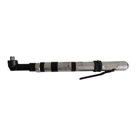
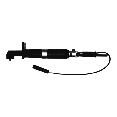
Stall Type Tools
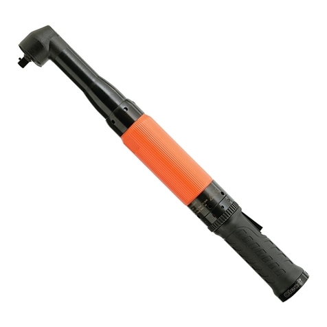
Clamp the flats of the handle in a vise with the tool in a
vertical position.
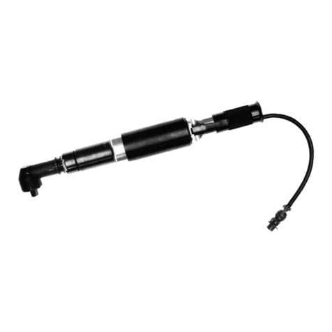
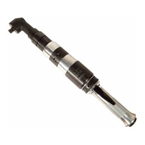
Using a suitable wrench, loosen (left hand threads) the
clamp nut, No. 869878, and remove the angle head assem-
bly. Unscrew and remove the gear case assembly.
Slip the motor unit out the front of the handle. It may be
necessary to bump the handle on the work bench to loosen
the motor.
SUBASSEMBLIES DISASSEMBLY
Right Angle Head
Remove the bearing cap lock screw (1/16 hex), No. 867997,
and unscrew (lee hand threads) the bearing cap. Clamp the
square drive in the vise and use a sort mallet to drive the
angle head off. Press the spindle out of the driven gear and
then press the spindle out of the ball bearing.
Unscrew and remove the bearing retainer, No. 869877, and
grease plug, No. 867546. Use a suitable driver to drive the
pinion gear out of the housing.
Clecomatic Clutch
Important: The adjustment cover, No. 869918, retains the
ball spring, No. 869919, and steel ball, No. 842162, and
care should be exercised to prevent their loss.
Use a 5/32" (3.96mm) diameter pin to lower the clutch
adjustment. This will allow the clutch retainer ring, No.
869920, to be removed from the clutch housing. Remove
the clutch assembly from the housing. Use a suitable
bearing puller to remove ball bearing, No. 847022, drive
shaft washer, No. 869918, trip sleeve spring, No. 869918,
and trip sleeve, No. 867670, from the drive shad No.
869915.
NOTE: Trip Plunger, No. 869916, trip plunger spring, No.
867671, and two (2) balls, No. 842161, should also be
removed at this time. Use a sharp pointed instrument to
remove the cam retainer ring, No. 869921, from the ball
retainer, No. 869914. Slip the drive shaft, No. 869915, and
clutch cam, No. 869913, out the rear of the ball retainer, No.
869914.
Gear Case
Slip the entire gear train out the rear of the gear case. The
2nd reduction idler gears may be removed for inspection by
driving the idler gear pins, No. 869908, out the rear of the
spider.
Motor
Use a soft faced mallet to drive the rotor out of the front rotor
bearing, No. 847528. This will allow the removal of the front
bearing plate, No. 869923, cylinder, and five (5) rotor
blades, No. 869927, from the rotor, No. 203147. Clamp the
rotor lightly in the vise and unscrew the rotor lock nut, No.
865352. Rest the rear bearing plate on the vise jaws and use
a soft faced mallet to drive the rotor out of the rear rotor
bearing.
Handle
Unscrew the inlet bushing, No. 869933, for inspection of the
throttle components. The air inlet screen, No. 843656,
should be washed in a solvent and blown out in the reverse
of normal airflow. Replace if damaged or clogged.
REASSEMBLY
The tool is reassembled in the reverse order of disassem-
bly. Clean all parts thoroughly in a solvent and inspect for
damage or wear. Check all bearings for wear which can be
detected by excessive end play and/or roughness which
would indicate a brinelled condition. The rotor blades should
be replaced if they measure less than 3/8" (9.5mm) at either
end. All gear teeth, bearings, and pins should receive a
close inspection and be replace if necessary. All gears and
open bearings should receive a generous amount of No. 2
Moly grease during reassembly.
Motor
To assemble the motor, install the rear rotor bearing into the
rear bearing plate. Make sure the outer bearing race is firmly
seated in the bearing plate. Clamp the rotor body lightly in
the vise with the threaded end up and slip the rear bearing
plate assembly onto the rotor shaft far enough for the
bearing lock nut to start. Tighten the lock nut until there is
approximately .0015" clearance between the rotor and
bearing plate. The outer bearing race should be firmly
seated and the rotor bumped forward when checking this
clearance. Pack both rotor bearings with a good grade of
No. 2 Moly grease after assembly of the motor unit.
IMPORTANT: During reassembly of the complete tool, it is
important that the motor be free. After the tool is completely
assembled, the right angle square drive spindle should turn
freely using a small hand wrench. If the spindle does not turn
freely, the motor should be checked for proper spacing. Do
not run the tool until the spindle turns freely. Failure to do this
could result in damage to motor components.


