6
GEAR TRAIN DISASSEMBLY
Single Reduction
The spider should be pressed out the rear of the gear case, No.
202889. Remove the retainer ring, No. 844364, and press the
bearing, No. 847147, out the front of the gear case.
If replacement of the idler gear pins is necessary, they should
be pressedouttherearofthespider.SeeFig.1for replacement
pin height.
Fig. 1—Single Reduction Spider
Double Reduction
Both spiders should be removed from the rear of gear case,
No. 202875. Remove the retainer ring, No. 844364, and press
the bearing, No. 847147, out the front of the gear case.
If replacement of the idler gear pins is necessary, they should
be
pressedouttherearofthespider.SeeFig.2forreplacementpin
height.
-10 2nd Reduction Spider -5, -7 & -10 1st Reduction Spider
Fig. 2—Double Reduction Spiders
LIGHT RING KIT and HOUSING SHROUD DISASSEMBLY
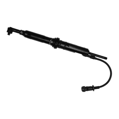
Remove inlet bushing No. 203355, and slide back exhaust
deflector No. 203356. Unplug wiring and remove wire bundle
No. 203371. All caps and throttle lever must be removed from
backheadNo.203353, before housing shroud No. 203357, can
beremoved.Loosenallthreesetscrews(2)No.843518andNo.
847282, in light ring several turns. Slide housing shroud off the
backhead. NOTE: Do not rotate the light ring kit or housing
shroud when removing from backhead to prevent breaking
wires. Hold pig tail connection while removing light ring kit and
housing shroud from backhead.
MOTOR DISASSEMBLY
Use a soft-faced hammer to drive the rotor out of the front rotor
bearing, No. 619377. This will allow the cylinder and five (5)
rotor blades to be removed from the rotor. Set the rear bearing
plate on the vise jaws with the rotor facing down. Use a 7/32"
punch to drive the rotor out of the rear rotor bearing.
SERVICE INSTRUCTIONS
DISASSEMBLY—GENERAL (ALL MODELS)
Disconnect tool from air supply. Unscrew (left hand threads)
and remove the right angle head and the angle head adapter
No. 869034. Remove pin No. 844111, from the exhaust deflec-
tor No. 203356. Unscrew the inlet bushing No. 203355 and
exhaustdeflectorfarenoughtounplugwirebundleNo. 203371.
Unscrew valve caps(2) No. 203362, No. 203360 throttle lever
No. 867877. Remove throttle valve and all related parts. Re-
move housing shroud No. 203357, from rear of backhead No.
203353,verycarefullytopreventdamagingthewiring.Unscrew
(lefthand threads) transducerhousing and liftcarefully,feeding
the wiring through the hole in the backhead. To remove motor
assembly, tap backhead lightly on a soft surface.
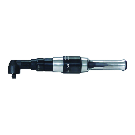
"K" RIGHT ANGLE HEAD DISASSEMBLY
To disassemble the right angle head, unscrew the spindle
bearing cap. This will permit the removal of the spindle assem-
bly.
The pinion bearing retainer, No. 863564, may be removed by
utilizing a 5/8" hex nut and a 5/8" deep socket. Drop the hex nut
over the pinionshaft and engage the hex in the bearing retainer
and unscrew the retainer using the deep socket. Unscrew the
plug, No.842366, and using a suitable driver, drive thepinion,
No. 202200, and related bearings out of the angle head.
'M" RIGHT ANGLE HEAD DISASSEMBLY
Using a suitable spanner wrench, unscrew (left hand threads)
thebearing cap, No. 864396.Removethe spindle, ball bearing,
No.842517, and driven gear by clamping the spindle in a vise
and driving the right angle housing, No. 869048, away from the
spindle using a soft faced mallet. The ball bearing can now be
removed by pressing the larger end of the spindle through the
bearing I.D.Press the smaller end of the spindle through the
gear to remove the driven gear. The pinion bearing retainer,
No.863564,may be removed by utilizing a 5/8" hex nut and a 5/
8" deep socket. Drop the hex nut over the pinion shaft
a n d e n g a g e t h e h ex i n t h e b e a r i n g r e t a i n er and unscrew the
retainer using the deep socket.
15°& 30°ANGLE HEAD DISASSEMBLY
Clamp the hex drive of the pinion gear in a vise and drive the
angleheadoff(useasoft-facedmallet).Removethetwo(2)hex
nuts No. 833785, and unscrew the two (2) bearing post screws
No. 847027. Unscrewing the four (4) base plate screws will
allowthe base plate No. 869207,andrelated components to be
removed from the angle head. Note: When removing the base
plate, care should be exercised to avoid the loss of the fifty-six
(56)steelballs No. 842980, located in the two (2) ball races No.
864264. The angle head can now be broken down into its basic
components for inspection and replacement of parts.
TRANSDUCER DISASSEMBLY
Removetheringgear andtransducer assemblyfrom therear of
the transducer housing. Remove the retainer ring No. 619017
from the transducer and tap lightly on a soft surface to remove
bearing,No.847566.Thenremovethetransducerfromthe rear
of the ring gear.
.240
.255
Front Rear
.360
.375
Front Rear


