Clemco Apollo 600 CE User manual

Revision: 01.2015
Clemco
International GmbH Carl-Zeiss-Straße 21 Tel.: +49 (0) 8062 –90080
Germany Web: www.clemco-international.com
O W N E R 'S M A N U A L
RESPIRATOR MODEL
APOLLO 600 CE
CLEMCO SUPPLIED AIR RESPIRATOR

Page 2
INDEX
1SCOPE OF MANUAL 4
2APPLICATIONS AND LIMITATIONS 4
2.1 General Description 4
2.2 Toxic Dust Poisoning 6
2.3 Ear Protection 6
3DESCRIPTION 6
4PREPARATION 6
5AIR SUPPLY 7
5.1 Air Quality 7
5.2 Air Volume Velocity, Pressure and Hose Length 8
6OPERATION 8
7ADJUSTMENTS 9
7.1 Control Valve (part. no.: 100074) 9
7.2 Adjustment of Suspension 10
8MAINTENANCE PROGRAM / REPLACEMENT PARTS 10
8.1 Replacing Inner Lens 11
8.2 Replacing Outer Lens and Perforated Cover Lenses 11
8.3 Replacing Suspension 12
8.4 Cape 12
8.5 Replacement of Collar (only required if the nylon cape is used) 13
8.6 Replacement of Lens Frame 13
8.7 Replacement of Chin Strap 13
9SERVICE MAINTENANCE AND CLEANING 13
9.1 Filter 13
9.2 Nylon-Cape 13

Page 3
9.3 Leather Cape 13
9.4 Rubber and ASS –Cape 13
9.5 Collar 14
9.6 Sweatband / Suspension 14
9.7 Helmet Assembly 14
9.8 Lenses 14
10 STORAGE 14
10.1 Daily Storage 14
10.2 Long Duration Storage 14
11 SPARE PARTS 14
11.1 Helmet 14
11.2 Air Control Valve 15
11.3 Components 15
11.4 Additional parts - Options 18

Page 4
1 Scope of Manual
This manual covers setup, operation, maintenance, replacement parts, and important warnings for safe
operation of the Clemco Apollo 600 CE Supplied-Air Respirator.
Read the entire manual before installing or operating the equipment.
The following additional equipments may be used in conjunction with the Apollo 600 CE Respirator:
Part no.
Titel / Description
Remarks
03580 D resp.
03527 D
Air filter CPF-20 or CPF-80
Installation between air supply and air supply hose
23825D
Clem Cool air conditioner
In place of the air control valve to the air conditioning
04411I
Climate control
In place of the air control valve –optionally for heat-
ing or cooling the air
25189D
DLX padded suspension kit
Supplementary mounted in the Apollo 600, for a bet-
ter more convenient fit.
24310D
Leather cape for Apollo 600
In place of the nylon capes (example during heavy
abrasive recoil)
24405D
Rubber Cape 4436
Instead of the nylon cape when a very intense recoil
of abrasive appears. Lighter than the leather cape.
24406D
ASS-Cape 4436 RA
Instead of the nylon cape to allow rope access.
Heavy duty rubber front.
2 Applications and limitations
2.1 General Description
The Apollo 600 CE was specially developed and approved for blasting. (MSHA - NIOSH and EN 271)
The following Cautions and Limitations have to be followed:
-The supplied air has to be in accordance with the EN 12021.
- The Apollo 600 CE is not suitable for any other work such as welding or painting!
- Only for the use in atmospheres which do not represent any imminent danger for life and health and
which contains a minimum oxygen volume of 19,5%.
- It is not allowed to use this product with pure oxygen or with oxygen enriched air.
- Not for the use in flammable atmospheres.
- The Apollo 600 CE protects the wearer’s head and neck from impact and abrasion caused by rebound-
ing abrasive.
- The helmet is suitable for the usual vertical or a bit slopy posture of the head. In forced postures like
the horizontal posture when lying, the air indicator will not work.
- The helmet can be used at temperatures as follows:
oWorking: -6° to +40°C.
oShipping and transition -20° to +50°C
oStocking : 0 to +30°C.
- If the product is used under a temperature of 4°C the water content has to be reduced to avoid freezing
of the product.
- The supplied air must have a pressure between 6 and 8bar. To assure this pressure you can use our
Air Filter CPF 20 which has an integrated pressure regulator (Part No: 03580 D). See also 5.2.

Page 5
- In the moment of highest breathing air requirement during the highest work rate, a sub pressure in the
helmet can appear.

Page 6
2.2 Toxic Dust Poisoning
For operator safety clothing Type1 and Type 2, according to EN ISO 14877: 2002 (D) the following
applies:
Recent research by the Occupational Safety and Health Administration (OSHA) has discovered poten-
tial risks of lead poisoning to unprotected abrasive blasting operators and other personnel who may be
exposed to lead-containing dust in the abrasive blasting vicinity.
This lead poisoned dust is primarily a result of removing lead containing paint.
Danger for life and health can also be caused by colours which contain heavy metal, asbestos or other
toxic material dust. Lead poisoning can cause death. The maximum ground level concentration is de-
clared by TRGS 900 to 0,1 mg/m3.
For that reason it is very important that the Blasting Contractor determines which kind of paint he has
to remove. If necessary he has to use then a helmet or an additional Air Respirator which is admitted
for the use with one of those materials.
The blasthood Apollo 600CE, can be used in any combination with operator safety clothing Typ 3
according to EN ISO 14877: 2002 (D) without any restriction in an ambient with such toxics.
2.3 Ear Protection
Always use properly fitted ear plugs when using this equipment.
3 Description
The main components for the minimal version from a respirator are as follows:
Helmet with cape attachment strap, suspension and adapted cape
Breathing air-hose (length: approx. 1000mm)
Breathing air-supply hose (length: 5m) with quick-fitting pipe union (female)
Air control valve with belt
Hood
4 Preparation
Please control respective prepare the following components:
(1) Adjust Helmet Suspen-
sion.
Trim helmet suspension by adjusting screw to your head and adjust
chin strap to correct length (see also 7.2).
(2) Check that the lens sys-
tem is in place.
Inner lens (Replacement see 8.1)
Outer lens (Replacement see 8.2)
Perforated cover lenses (Replacement see 8.2)
The respirator assembly must never be used without the fixed inner
lens, outer lens and the cover lenses!
(3) Air Supply Hose.
Use the quick fitting pipe union to attach the air supply hose to the air
control valve.

Page 7
The other end of the air supply hose attach to the Air Filter CPF - 20
respective CPF - 80 (more than one blaster).
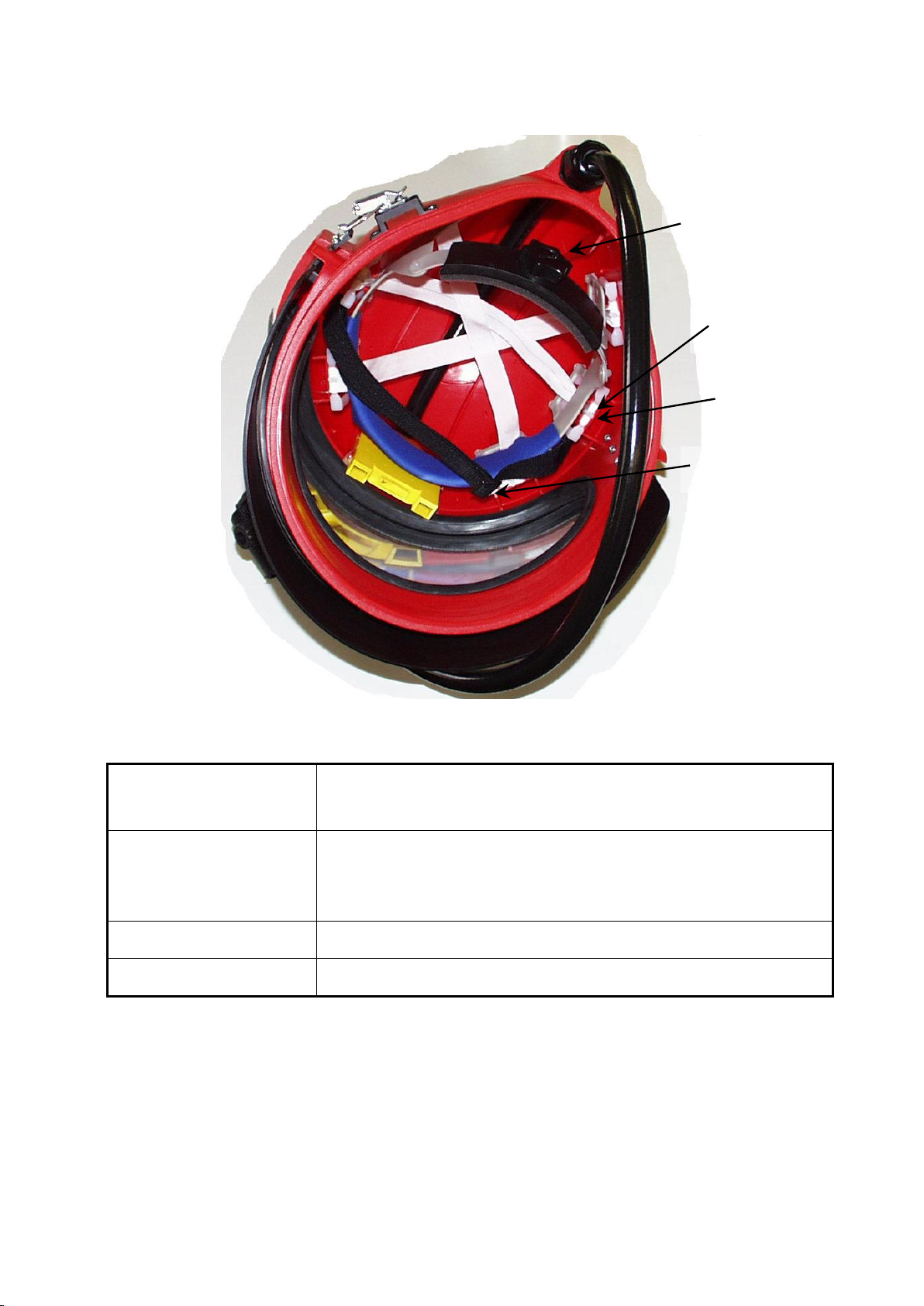
Use moulded-in handle to carry the respirator. Never hold, carry or
hang the respirator by the breathing hose!
Mishandling the respirator in this manner may damage the hose!
5 Air Supply
Air supply to this respirator system is a critical component for the safety of the user and is not
included in this delivery. Read this section carefully. Poor quality air will cause serious respiratory
injury or death to the user (see 2.2).
5.1 Air Quality
The compressed breath air has to be conform to EN 12021.
A supply pressure between 6-8 bars has to be assured. The supply pressure can be regulated over our
CPF 20 filter with integrated pressure regulator (p/n 03580D) so that the blaster is provided with the right
air quantity.
The quality of air supplied to the respirator is extremely critical to the safety of the user. Special care must
also be taken to avoid accidental connection to any other gas lines, such as oxygen, acetylene or nitrogen.
Never connect a breathing air line to an air source that has not been tested for gas and particulate
contamination.
Do not use piston type (oil bath) compressors for breathing air. These compressors may produce
dangerous levels of carbon monoxide.
The presence of unacceptable levels of carbon monoxide (CO) or other gases in the breathing air
can cause death to the user.
Breathing air must be only used in following conditions:
Prior to using the respirator, read the owner’s manual and all instructions, labels, and warnings related
to the compressed air source. Take special care about all the statements and warnings from the com-
pressor producer.
Warning: There could appear a negative pressure in the blast hood during inhala-
tion caused by a high intensity of labour.
That is why the air control valve should be opened wider while a high intensity of labour in order
to avoid the infiltration of dust in the blast hood.
We recommend our carbon monoxide monitor, CMS-3 for controlling the concentration of carbon monox-
ide.
Regardless to the air compressor type, precautions must be taken to prevent contaminants from
entering through the compressor intake. The compressor inlet must be located away from all sources
of toxic contaminants including carbon monoxide which is found in engine exhaust and in any form
of combustion. No vehicles should be allowed near the compressor intake.

Page 8
The precautions described above also apply to portable compressors. In addition, in the case of
engine-driven compressors, precautions must be taken to prevent engine exhaust gases from en-
tering the air intake of the compressor. Compressor engine exhaust should be piped to a location
safely downwind from the compressor air intake. Compressors may vary in design and operation.
A fitted Air Filter like the CPF-20 Filter (part No 03580 D), has to be interconnected and must be
maintained regularly, to filter bad smells, oil fog, condensed water, rust from pipes and other con-
tents.
For trouble-free blasting we recommend an air supply free of oil and water.
5.2 Air Volume Velocity, Pressure and Hose Length
The quantity of air needed from a blaster for having enough oxygen to breathe is between
130l/min ... 190l/min.
This minimal quantity makes sure that the volume indicator is on function, which means that the flag is
pulled in –otherwise the flag falls down.
As supply hoses between the air filter and the control valve you may use only CE-approved hoses with
safety couplings (see section 11 –spare parts).
The maximum hose length between the filter and the control valve can be 40m. If it is necessary to use
longer hoses you have to contact the manufacturer to take appropriate measures.
The maximum pressure at the supply hose is 8bar.
6 Operation
Prior to the operation, the helmet, breathing tube, air supply hose, air entry pots and fittings must
be thoroughly inspected and cleaned of all dust and debris. Also inspect the helmet suspension
and adjust it if necessary (Adjustments see section 7.2).
The following steps have to be done before setting into operation:
(1) Air supply.
Start compressor.
Open service valve to pressurize the air supply line.
(2) Check air pressure.
Pressure must be set with the connected respirator.
View from inside
Too less air volume velocity
Enough air volume velocity

Page 9
(3) Check equipment.
Check all safety and breathing equipment used in conjunction with the
respirator, as recommended by the manufacturer.
(4) Check air supply hose.
Check air supply hoses and connections for tightness and leaks.
(5) Put the respirator on.
Put the hood on.
Put the respirator on (keep it as upright as possible to prevent abrasive
from falling inside).
Position the knit cuff on the inner collar so that it fits comfortably. The col-
lar assists in the prevention of dust entering the helmet. Do not allow shirt
collars or other matter to interfere with the fit the cuff provides around the
user’s neck.
Pull the cape down to fully extend it, and connect the straps on each side
under the arms.
Put the belt and control valve on over the cape, Buckle the belt around the
waist and tighten it using the adjusting slide.
7 Adjustments
7.1 Control Valve (part. no.: 100074)
Picture 1: Control valve
Clemcos Air Control Valve allows the user to increase or decrease the volume of breathing air while wear-
ing the supplied air respirator. To regulate it the button on the side has to be turned.
If connected properly to the air supply the valve allows a regulation of breathing air in a range of 130l/min
to 400l/min.
CLOSE
OPEN

Page 10
7.2 Adjustment of Suspension
Picture 2: Suspension
The following steps have to be done before setting it into operation:
(1) Remove Cape.
Open buckle by pressing the small lever and pull out belt.
Remove cape.
(2) Adjust suspension.
Trim suspension by adjusting screw to your head. Trimming clockwise
suspension gets narrower; trimming anti-clockwise suspension gets
wider.
(3) Adjust chinstrap.
Adjust chinstrap to correct length by moving the “buckle”.
(4) Reattach cape.
See 8.4.
The suspension maintains a fixed distance between the head and the helmet. The suspension must
be properly installed and adjusted to provide the protection and comfort for which the helmet is
designed.
8 Maintenance Program / Replacement Parts
The helmet, the hoses, air entry pots and fittings should be checked for dust or debris every day, and
should be cleaned before using.
Periodically inspect and clean the foam filter and screen in the alternate air control valve.
Adjusting screw:
clockwise narrower,
anti-clockwise wider
“Buckle“
chinstrap
Holder for sus-
pension
Clip

Page 11
After using the helmet it should be stored in a clean and dry area by hanging the respirator by the
handle.
8.1 Replacing Inner Lens
(1) Open frame.
Open latch and hang out frame.
(2) Remove inner lens.
Open window gasket in upper area from outside by hand.
With the other hand press out lens from inside.
Check that window gasket still fits well.
(3) Place new lens.
Clean gasket and moisten groove for lens with a mild soap-water.
Place new lens centred on gasket and push it roundabout into the
groove of the gasket by using the mounting-tool. Avoid scratches on the
lens! (See also picture 3).
(4) Close frame again.
Hook in frame in latch and close it.
8.2 Replacing Outer Lens and Perforated Cover Lenses
Up to five cover lenses may be installed at one time. For maximum visibility we recommend to install only
so many lenses to last during a work period.
Preparing lenses in the following manner will permit lenses to be pulled off easily by a user wearing heavy
gloves:
(1) Open frame.
Open latch and hang out frame.
(2) Remove outer lens.
Remove outer lens carefully from mushroom buttons.
(3) Remove used cover
lenses.
Remove perforated cover lenses respectively frame of used cover lenses
as well carefully from mushroom buttons.
(4) Place new perforated
cover lenses.
Place straps to hinge side and pull through all straps except the last and
press cover lenses on mushroom buttons.
(5) Place new outer lens.
When placing the new outer lens look to it that there’s no dust or dirt be-
tween the lenses.
Press outer lens on mushroom buttons.
(6) Close frame again.
Hook in frame in latch and close it.

Page 12
Picture 3: Replacing inner lens by using mounting-tool
8.3 Replacing Suspension
Pull out suspension carefully from adaptors (see also picture 2).
The clips are supposed to fix the suspension in the helmet well. The bent side has to face to the centre of
the helmet.
When placing the new suspension look to it that the chinstrap is placed in front of the suspension.
8.4 Cape
When the cape becomes soiled or requires replacement, it can easily be removed as follows:
(1) Detach cape.
Open buckle by pressing the small lever and pull out belt
Remove cape.
(2) Reattach new cape.
Put in-sewed spring of cape in groove of helmet beginning at the front
(seam of cape has to face backwards).
Attach spring of cape all around the helmet completely in groove.
Place belt that way that buckle is placed opposite to hook of frame and
end of belt shows backward.
Mount belt, check position of cape and close belt with ratchet.

Page 13
8.5 Replacement of Collar (only required if the nylon cape is used)
The inner collar plays an important roll in controlling air escape from the helmet and preventing ingress of
dust. To replace or wash the collar it has to be detached with the zip from the cape (see point 9 for service
maintenance and cleaning).
The cape must be replaced when the collar is stretched to the point where it no longer fits snug
around the neck.
8.6 Replacement of Lens Frame
The lens frame must be replaced if a sealing is not ensured anymore or if the rubber latch doesn’t stay
closed. When changing the lens frame the silencing in the inner part of the helmet should be changed, too.
8.7 Replacement of Chin Strap
The chin strap must be replaced at the first sign of wear.
To get the chinstrap off the holder push it up into the helmet till it snaps out, then take it off the holders.
When replacing the new chinstrap look to it that the bevelled side shows to the centre of the helmet.
9 Service Maintenance and Cleaning
Follow washing instructions described in this section. Do not use any caustic chemicals or sol-
vents that may be irritating or harmful to the user, or which change the properties of the materials
used in any part of the respirator.
9.1 Filter
The filter (foam) is in the air control valve. Replace the foam filter at the first sign of soiling.
Therefore you have to remove the spring ring with a small screw jack and take off the dirty foam. Afterwards
reassemble these 3 parts in opposite order.
9.2 Nylon-Cape
The cape can be machine washed using warm water and mild detergent. Dry it in a clothes dryer at the
lowest temperature setting. Do not dry clean. See section 8.4 for removal and installation instructions.
9.3 Leather Cape
The cape can be brushed or cleaned with a wet sponge (Washing, chemical cleaning, ironing and chlorine
bleach are not allowed.)
9.4 Rubber and ASS –Cape
The cape can be cleaned with a wet sponge. (Washing, chemical cleaning, ironing and chlorine bleach are
not allowed.)

Page 14
9.5 Collar
For removing transpiration and dust the collar should be washed daily. Remove the collar from the cape
and wash it in warm water and mild detergent. Dry it in a clothes dryer at the lowest temperature setting.
Do not dry clean. See section 8.5 for removal and installation instructions.
9.6 Sweatband / Suspension
The sweatband, suspension, and chinstrap should be washed using warm water and mild detergent. See
section 8.3 for removing suspension.
9.7 Helmet Assembly
The helmet assembly should be cleaned with disinfectant. You can use the product “Indicur“ made by
„Henkel“.
WARNING! This product was only tested for agreeableness with our helmet. When using this product you
have to follow the instructions in the manual. For eventually occurring indigestibility with the skin or other
health damages we do not take any liability.
9.8 Lenses
Inner and outer lenses should be replaced when pitted or scratched. However mild detergent and water
can be used to clean them. Volatile solutions such as alcohol, gasoline or ammonia must be not used to
clean these lenses. Allow the lens to air dry; cloth and towels can scratch the lens surface.
10 Storage
10.1 Daily Storage
When respirator is not in use, it must be stored in a clean, dry area. Hang the respirator by the handle.
10.2 Long Duration Storage
After cleaning and thorough drying, the cape should be tucked inside the helmet (only the nylon, the rubber
and the ASS- cape). The respirator should then be placed in a plastic bag and the bag sealed to keep out
dust and moisture.
11 Spare Parts
11.1 Helmet
Pos.
Part-No.
Model
Description
-
24243 D
APOLLO 600 CE
Blast-Hood A-600CE + Air Control valve + Nylon cape
24315D
APOLLO 600 CE
Blast-Hood A-600CE+ Air Control valve + Leather cape
-
24213 D
APOLLO 600 CE
Blast Hood A-600CE with hose 5m
24244D
APOLLO 600 CE
Blast Hood A-600CE without auxiliary equipment

Page 15
11.2 Air Control Valve
Pos.
Part-No.
Model
-
04381 I
Filter set (foam-filter, screen an spring ring)
-
100042
Air Control valve complete
55
100074
Air Control valve without belt
11.3 Components
Pos.
Part-No.
Model
1
23800 A
Outer helmet shell A-600
2C
04491 I
Acoustical foam r.h.
2D
04492 I
Acoustical foam l.h.
2H
23815 D
Nylon cape A-600
24310D
Leather cape A-600
24405D
Rubber Cape 4436 for A 600
24406D
ASS- Cape 4436 RA for A-600
2H1
08740 I
Inner collar for A-60 and A-600
2I
04460 I
Chinstrap
2J
23806 I
Suspension A-600
2J1
23821 I
Clip A-600 head suspension (4 units/head suspension necessarily)
2L
23801 D
A-600 cape attachment
Pos.
Part-No.
Model
2L3
23803 D
A-600 draw latch window frame
2L4
24245 D
Screw M6x8 for latch
2M
23819 D
A-600 window gasket
2N
24308 D
Inner lens (1mm Polycarbonate; 5 pcs.)
2O
04361 I
Perforated cover lens 0,2mm (25 pcs.)
2P
24012 D
A-600 window frame complete
2P1
23810 D
A-600 window frame black
2P2
23812 D
A-600 hinge black
2P3
99269 D
Rivet (base)
2P4
04454 D
Rivet (head)
2P5
08738 I
Strike for window frame
2Q
23805 I
Screw for A-600 (6/32 x ½“)
2R
08924 I
Nut 3/8”
2W
04373 I
Outer lens 0,5mm (25 PK)
2Z
90266 D
Holder chinstrap
2AA
23805 I
Screw (6/32 x ½“)
2AB
23817 I
External tooth lock washer

Page 16
2Y
24316D
A-600 Latch base complete
2YA
23813 D
A-600 Latch base
2YB
04449 I
Draw latch
2YC
04438 I
Screw for A-600 (6/32 x ½“)
2YD
08924 I
Nut #6
50
100913
A-600 CE air indicator complete with hose
50
100915
A-600 air indicator
51
100914
Air hose black 1m
52
100917
A-600 high-strength cable gland
53
24263 D
Hose shell for 9mm air hose
54
01030 D
Hose connection
55
100042
Air control valve complete with belt
56
100421
5m Air Supply Hose 9mm with safety coupling and socket (CE-approved)
100406
10m Air Supply Hose 9mm with safety coupling and socket (CE-approved)
100404
20m Air Supply Hose 9mm with safety coupling and socket (CE-approved)
100405
40m Air Supply Hose 9mm with safety coupling and socket (CE-approved )
100403
Safety coupling 9mm (CE-approved)
100380
Ear plugs
10533 D
Owner’s manual
100586
Hood (Polypropylene)
24395D
Mounting-tool for inner lens

Page 17
Picture 4: Single components of Apollo 600 CE
A- Nylon cape for A-600 –p/n: 23815D
B- Leather cape for A-600 –p/n.: 24310D

Page 18
C- Rubber cape 4436 for A 600 p/n.: 24405D
D- ASS- Cape 4436 RA for A-600 p/n: 24406D
Picture 5 A… D: CE-certificated Capes for Apollo 600
11.4 Additional parts - Options
Clem Cool air conditioner
23825D
Climate control
04411I
DLX padded suspension kit
25189D
Table of contents
Other Clemco Respiratory Product manuals