Clemco BLAST HELMET APOLLO 600 CE User manual

Revision: 3
Clemco
International GmbH Carl-Zeiss-Straße 21 Tel.: +49 (0) 8062 – 90080
Germany Web: www.clemco-international.com
OWNER’S MANUAL
BLAST HELMET
APOLLO 600 CE
Supplied air respirator
with continuous air flow
Cat. III
Equipment class 4 B
in acc. with DIN EN 14594:2018

Page 2
TABLE OF CONTENTS
1SCOPE OF MANUAL 4
2APPLICATION AND LIMITATIONS 4
2.1 General description 4
2.2 Restrictions and information in acc. with DIN EN 14594:2018 4
2.3 Toxic dust poisoning 6
2.4 Ear protectors 7
2.5 Expiry date of the PPE or certain of its components 7
3DESCRIPTION OF THE EQUIPMENT 7
4PREPARATION 7
5AIR SUPPLY 8
5.1 Air quality 8
5.2 Air volume, pressure and line length 9
6OPERATION 9
7SETTINGS 10
7.1 Control valve (Art. no. 100074) 10
7.2 Adjusting the helmet suspension 11
8MAINTENANCE / REPLACING PARTS 12
8.1 Replacing the inner lens 12
8.2 Replacing the outer lens and cover lenses 12
8.3 Replacing the helmet suspension 13
8.4 Cape 13
8.5 Replacing the inner collar (nylon and ASS cape only) 14
8.6 Replacing the lens frame 14
8.7 Replacing the chin strap 14
9SERVICING / CLEANING 14
9.1 Filter 14

Page 3
9.2 Nylon cape 14
9.3 Leather cape 14
9.4 Inner collar 14
9.5 Sweatband/helmet suspension 14
9.6 Blast helmet 15
9.7 Inner lens 15
10 STORAGE 15
10.1 Daily storage 15
10.2 Long-term storage 15
11 REPLACEMENT PARTS 16
11.1 Helmet 16
11.2 Air control valve 16
11.3 Individual components 16
11.4 Additional parts 19

Page 4
1 Scope of manual
This manual covers the startup, operation, maintenance, replacement of parts and measures that ensure
the safe operation of the Apollo 600 CE protective helmet.
Read the entire manual before startup or operation of the equipment.
The following additional components may be used in conjunction with the Apollo 600 CE blast helmet:
Article no.
Description
Remarks
03580 D or 03527 D CPF-20 or CPF-80 air
filter
Installation between air supply and air sup-
ply line
23825D
Clem Cool air conditioner
In place of the pressure regulation valve to
cool the air
04411I
Climate control
In place of the pressure regulation valve to
heat or cool the air as required
These additional components are installed between the air supply and the air supply line.
25189D
DLX padded suspension
kit
Additional component for a better and more
comfortable fit
24310D
Leather cape for Apollo
600
In place of the nylon cape (e.g. if a lot of
blast media rebounds)
24405D
Rubber cape 4436
In place of the nylon cape (e.g. if a lot of
blast media rebounds); lighter than the
leather cape
24406D
ASS cape 4436 RA
In place of the nylon cape if using fall pro-
tection during blasting, rubber
22892D
CMS-2 carbon monoxide
alarm
Carbon monoxide monitor - located outside
the helmet
24613D
CMS-3 carbon monoxide
alarm
Carbon monoxide monitor - integrated in the
helmet
2 Application and Limitations
2.1 General description
The Apollo 600 CE blast helmet was developed especially for use in blasting operations and is approved
in accordance with DIN EN 14594:2018 (and MSHA-NIOSH).
2.2 Restrictions and information in acc. with DIN EN 14594:2018
a) The helmet enables the wearer to be supplied with breathable air, which must comply with EN
12021. The air is fed at a continuous flow rate to a mask via a breathing line. The equipment has
an adjustable air flow valve that is worn by the operator. An air supply line links the equipment
wearer with the air supply.
b) Excess and exhaled air is released to the ambient atmosphere. The following temperatures are
prescribed for:
Storage: 0°C to +30°C
Operation: -6°C to +40°C
Transport and handling: -20°C to +50°C

Page 5
c) The length of the line between the filter and the control valve on the helmet must not exceed 40
m. We sell the line in pre-cut lengths of 5, 10, 20 and 40 m. A maximum of three lines can be
connected.
d) The supplied air must have a pressure between 5 and 8 bar. This pressure can be ensured by
using our CPF 20 air filter with integrated pressure regulator.
e) The pressure in the air supply line must not exceed 8 bar.
f) To ensure that the operator is supplied with sufficient oxygen, the air flow should be between
130 l/min and 190 l/min. The air indicator will be activated by the minimum amount, i.e. the flag
will be retracted.
g) Warning:The helmet is intended for use in an atmosphere that does not represent an imminent
danger to human life or health and contains at least 19.5 % by volume oxygen. The operator
should be able to escape from this atmosphere without needing to use the helmet.
The Apollo 600CE helmet will not provide adequate protection in certain highly toxic atmos-
pheres caused by e.g. lead-contaminated dust from removing lead-based paints or other paints,
asbestos, heavy metals etc.
Lead poisoning may cause death. The maximum workplace concentration has been defined as
0.1 mg/m³ of air (TRGS 900). For this reason, the blasting contractor must always determine
which type of paint is to be removed and, if necessary, ensure that operators wear a blast hood
or helmet that is approved for use with these substances or an additional respirator. In accord-
ance with DGUV Regulation 112-190, Class 4B blast protection equipment can be used at up to
500 times the threshold value.
h) Warning:During a period of very high use, peak respiration may produce negative pressure in
the helmet.
i) Warning:The air supply must comply with EN 12021.
j) Warning:The moisture content in the breathing air must be kept within the limits specified in EN
12021 to prevent the supplied air respirator with continuous air flow from freezing. If the equip-
ment is used at a temperature below 4°C, the moisture content must be limited to prevent freez-
ing.
k) Warning: The equipment must not be operated with pure oxygen or oxygen-enriched air.
l) Warning: Each operator connected to the air supply system must check that the capacity of the
system is adequate as described in the information provided by Clemco.
m) It is imperative that operators follow the instructions for donning the equipment as provided by
Clemco. These are contained in Sections 4 (Preparation) and 6 (Operation) of this owner's man-
ual.
n) The air supply line is not resistant to contact with hot surfaces or boiling water and is therefore
not labelled accordingly.
o) The air supply line is not antistatic and is therefore not labelled accordingly.
p) Do not use aggressive chemicals or solvents to clean the equipment. This may irritate or harm
the operator and alter the properties of the material used. Please also consult the instructions
concerning cleaning products and disinfectants in Section 9 of this owner’s manual.

Page 6
q) Not applicable
r) Warning: Particular attention must be paid to ensuring that the equipment is not accidentally
connected to other gas supplies, e.g. oxygen, acetylene or nitrogen. Never connect the breathing
air line to an air source that has not been tested for gas or particulate contamination.
s) The operator must assess the risk of potentially dangerous substances (e.g. nitrogen) at the
workplace.
t) The blast helmet is labelled in the customary manner. This label is clearly visible and durable.
Explanation of the respirator label (Section 7, EN 14594:2018):
Line 1: Type designation Apollo 600
Line 2: Serial number of the blast helmet currently a five-digit number
Line 3: Number and year of the European standard and equipment class EN 14594 : 2018
4B
Line 4: left - Storage temperatures to which the respirator is resistant – symbol acc. to EN132
0°C to +30°C
Line 4: middle – Month and year of manufacture (MM-YYYY) (example: 04 – 2019)
Line 4: right – Symbol: “See information provided by manufacturer” open book with “i”
Line 5: Name of manufacturer Clemco International GmbH
Line 6: Address of manufacturer Clemco International GmbH, Carl-Zeiss Str. 21, 83052
Bruckmühl
Line 7: Country of manufacture Made in Germany
Line 8: CE symbol and number of the notified monitoring body CE symbol and number of the
notified monitoring body
u) The cape and cape fastener are also labelled. The blast helmet is not suitable for use for other
operations such as welding or painting.
-The helmet is not suitable for use in flammable atmospheres.
-The helmet can be worn with the head in the usual vertical or slightly inclined position.
-The air indicator will not function in forced postures, e.g. with the head in a horizontal position
when lying down.
-The helmet also protects the skin on the operator’s head and neck from grazing caused by re-
bounding blast media.
-The quality of the air supply is critical and very important for ensuring the safety and wellbeing
of the operator.
Do not use a piston compressor (oil bath) to generate the breathing air as there is a great risk it
may produce high carbon monoxide concentrations.
The presence of excessive carbon monoxide concentrations may result in the operator’s death.
-If special air sources are used, e.g. a cylinder trolley or portable air tanks, these must be
equipped with warning devices in accordance with EN14594:2018.
v) A maximum of four operators can be connected simultaneously to the CPF filter.
2.3 Toxic dust poisoning
The following applies for model 1 and model 2 protective clothing in accordance with DIN EN ISO
14877:2003 (D):
Research has identified the potential risks of lead poisoning to unprotected operators and other per-
sonnel who may be exposed to lead-containing abrasive dust in the vicinity of abrasive blasting oper-
ations. This dust is primarily the result of removing lead-containing paints. A risk to human life and
health may also result from paints containing heavy metals, asbestos or other toxic dust.

Page 7
For this reason, the blasting contractor must always determine which type of paint is to be removed
and, if necessary, ensure that operators wear a blast hood or helmet that is approved for use with
these substances or an additional respirator.
Lead poisoning may cause death. The maximum workplace concentration has been defined as 0.1
mg/m³ of air (TRGS 900).
In accordance with DGUV Regulation 112-190, Class 4B blast protection equipment can be used at
up to 500 times the threshold value.
2.4 Ear protectors
Ear protectors must be worn when using the blast helmet.
2.5 Expiry date of the PPE or certain of its components
The equipment must be properly serviced, maintained and stored. All rubber components must be re-
placed at the latest 5 years after the date of manufacture. It is recommended that the blast helmet is
replaced after a maximum of 10 years.
3 Description of the Equipment
The minimal version of the blast helmet consists of the following components:
•Helmet with chin strap, suspension and cape
•Breathing air line (length approx. 1,000 mm)
•Air supply line (length 5 m) with quick coupling (female)
•Air control valve with belt
•Hood
4 Preparation
Check and/or prepare the following components:
(1) Adjust the helmet sus-
pension.
−Fit the helmet suspension to the operator’s head using the adjusting
screw and adjust the chin strap to the correct length (see also 7.2).
(2) Check that the lens sys-
tem is in place.
−Inner lens (replacement, see 8.1)
−Outer lens (replacement, see 8.2)
−Perforated cover lenses (replacement, see 8.2)
The blast helmet should never be used without the inner lens, outer
lens and cover lenses in place.
(3) Air supply line −Attach the air supply line to the air control valve using the quick cou-
pling.
−Attach the other end of the line to the air filter, either CPF-20 or CPF-
80 (more than one operator).
Never carry the blast helmet by the air line but always use the han-

Page 8
dle to avoid damage to the air line.
5 Air Supply
The air supply to the blast helmet is a critical element of operator safety and is not included in the
scope of delivery. Please read this section with particular care. Poor air quality may result in ill-
ness or death of the operator (see 2.2).
5.1 Air quality
The air supply must comply with EN 12021.
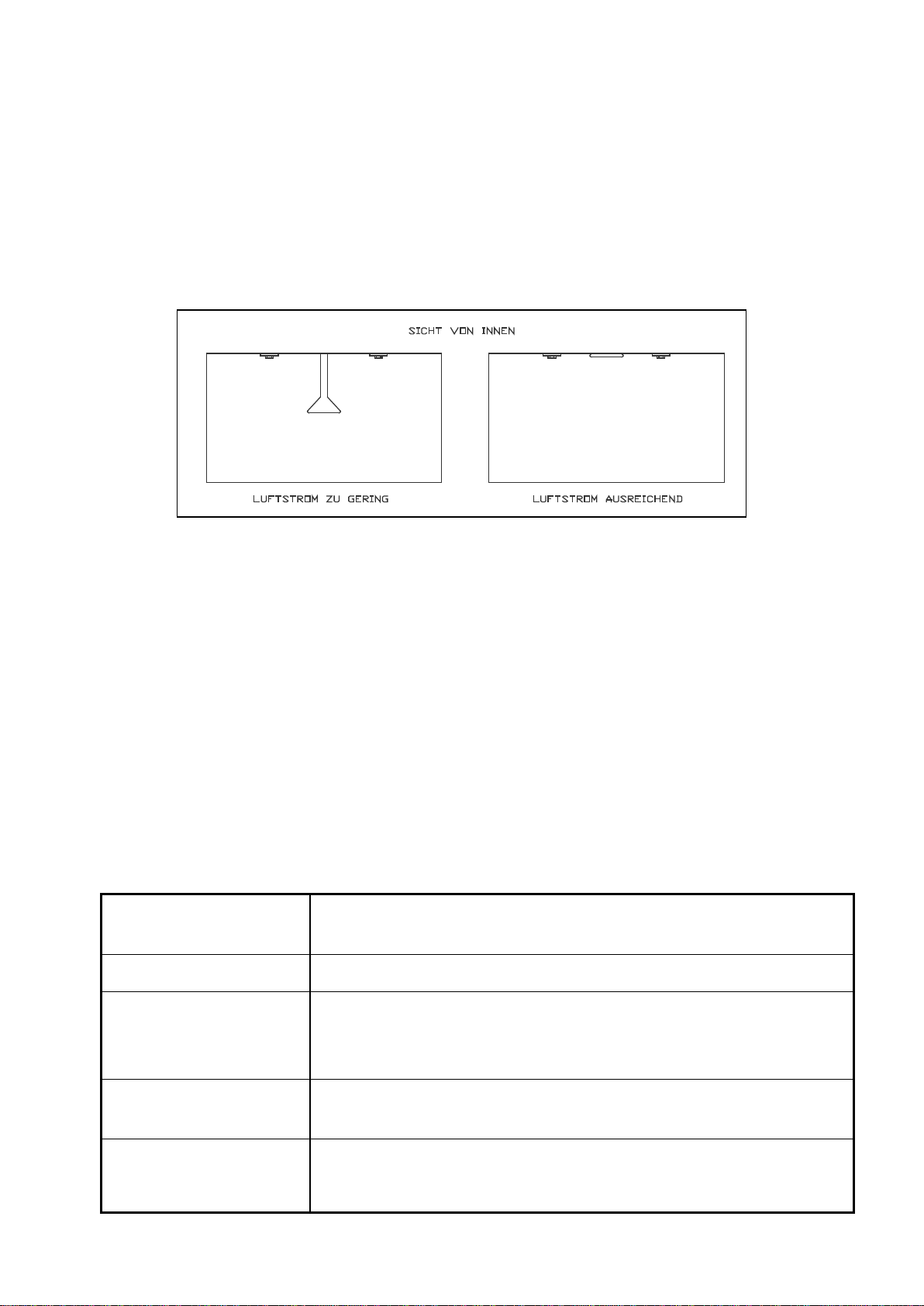
A supply pressure of 6 - 8 bar must be ensured. This can be achieved using our CPF 20 air filter with
integrated pressure regulator (Art. no. 03580D) so that the right air flow is available (see also 5.2).
The quality of the air supply is critical and very important for ensuring the safety and wellbeing of the
operator. Particular attention must be paid to ensuring that the apparatus is not accidentally connected to
other gas supplies, e.g. oxygen, acetylene or nitrogen.
Never connect the breathing air line to an air source that has not been tested for gas or particu-
late contamination.
Do not use a piston compressor (oil bath) to generate the breathing air as there is a strong risk it
may produce high carbon monoxide concentrations.
The presence of excessive carbon monoxide concentrations may result in the operator’s death.
The breathing air must meet the following requirements:
-The air supply must comply with EN 12021.
-Before using the helmet, please read the owner’s manual, all instructions and labels, and all warnings
concerning the compressed air source. Please observe the compressor manufacturer’s state-
ments/warnings concerning the use of the compressor.
Warning:
During intense use, respiration may produce negative pressure in the helmet.
-During intense use therefore, the air control valve needs to be opened wider to prevent the ingress of
dust into the helmet.
-If using an oil-lubricated compressor for the air supply, a high temperature monitor and/or a carbon
monoxide alarm should be fitted. If only a high temperature monitor is fitted, the air must be regularly
tested for the presence of carbon monoxide. The user is responsible for testing the breathing air, the
compressor, the carbon monoxide alarm, the air filter and the wearing parts. An overheated or poorly
maintained compressor may produce carbon monoxide or an unpleasant smell. It is also possible to use
systems to remove or convert carbon monoxide in order to ensure good breathing air quality.
-When using a compressor, the air intake must be positioned to prevent the intake of contaminants, e.g.
carbon monoxide and oil components found in exhaust gases. This applies especially when using porta-
ble compressors. For this reason, no vehicles or motor-powered equipment should be operated in the
vicinity of the compressor.
An appropriate filter (e.g. CPF 20, Art. no. 03580 D) must be fitted and regularly serviced to remove un-
pleasant smells, oil mist, condensation, rust from pipes and other constituents.

Page 9
-We recommend the use of our CMS-2 or CMS-3 carbon monoxide alarm.
-The compressed air used must be free from oil and water.
5.2 Air volume, pressure and line length
To ensure that the operator is supplied with sufficient oxygen, the air supply should be between
130l/min and 190l/min.
The air indicator will be activated by the minimum amount, i.e. the flag will be raised if the amount is
higher and lowered if it is lower.
Only CE-approved supply lines with safety couplings should be used to connect the air filter and the reg-
ulating valve (see Section 11: Replacement Parts).
The length of the line between the filter and the control valve on the helmet must not exceed 40 m. If it
is necessary to use a longer line, please contact the manufacturer to define suitable measures.
The pressure in the supply line must not exceed 8bar.
6 Operation
Prior to operation, the helmet, breathing air line, air supply line, air intake and all connections
must be thoroughly inspected and cleaned of all dust and debris. The helmet suspension should
also be inspected and adjusted if necessary (see 7.2 - Adjustments).
The following steps must be taken before operating the helmet:
(1) Air supply * Start the compressor.
* Open the service valve to pressurise the air supply line.
(2) Check the air pressure. Make adjustments at the air filter.
(3) Check the equipment. * Protective equipment
* Helmet
* Breathing air supply
(4) Check for leaks and fit. * Supply lines
* Connections
(5) Put on the equipment. * Put on the hood.
* Put the helmet on, ensuring as far as possible that no blast media gets

Page 10
inside it.
* Correctly position the chin strap and inner collar.
* Pull the cape down and fix below the arms using the two rubber straps on
each side.
* Put on the belt with the air control valve and tighten it well.
7 Settings
7.1 Control valve (Art. no. 100074)
Figure 1: Air control valve
The Clemco air control valve allows the operator to increase or decrease the air flow by turning the knob
at the side while wearing the helmet. When the air supply is properly connected, the valve allows the
breathing air to be regulated between 130 l/min and 400 l/min.

Page 11
7.2 Adjusting the helmet suspension
Figure 2: Helmet suspension
The following steps must be taken to adjust the helmet suspension:
(1) Remove the cape. * Open the buckle on the cape belt by pressing the small lever and pull-
ing the belt out.
* Remove the cape from the helmet.
(2) Adjust the helmet sus-
pension.
Use the adjusting screw to adjust the helmet suspension to the operator’s
head size. Turn the screw clockwise to make the helmet suspension
tighter; turn the screw counter-clockwise to make the helmet suspen-
sion looser.
(3) Adjust the chin strap. Slide the “buckle” on the chin strap to adjust it to the operator’s head size.
(4) Reattach the cape. See 8.4.
The helmet suspension ensures a sufficient distance between the head and helmet. It must be
properly installed and adjusted to provide the protection and comfort that the helmet is designed
to achieve.
Adjusting
screw:
right tighter,
left looser
Chin strap
“buckle”
Suspension
holder
Clip

Page 12
8 Maintenance / Replacing Parts
* The helmet, all lines, the air inlet and all connections should be inspected for the presence of dust
and debris and cleaned before use. All parts should be inspected for wear and tear.
* Regularly inspect and clean the foam filter and screen filter in the air control valve and air inlet in the
helmet.
* After use, the helmet should be hung by the handle in a clean place.
8.1 Replacing the inner lens
(1) Open the lens frame. Open the lens frame latch and remove frame.
(2) Remove the inner lens. * From the outside, use one hand to pull up the lens gasket in upper
area.
* Use the other hand to push the lens out from the inside.
* Check the fit of the gasket.
(3) Fit new inner lens. * Clean the gasket and moisten the groove for the lens with mild soapy
water.
*
Place the new lens in the centre of the gasket and push it into the
groove of the gasket with the installation tool. Avoid scratching the
lens (see Figure 3).
(4) Close the lens frame
again.
Hook the frame back in the latch and close.
8.2 Replacing the outer lens and cover lenses
Up to five perforated cover lenses can be fitted simultaneously. However, to ensure maximum visibility,
we recommend using only the number of cover lenses necessary for the specific work operation.
Follow the instructions below to ensure that the cover lenses can be easily removed by an operator
wearing heavy work gloves.
(1) Open the lens frame. Open the lens frame latch and remove frame.
(2) Remove the outer lens. Carefully remove the outer lens from the mushroom-shaped studs.
(3) Remove the used cover
lenses.
Carefully remove the cover lenses or remnants of the cover lenses from
the mushroom-shaped studs.
(4) Fit the new cover lenses. Position the tabs on the hinge side.
Pull all except the last tab through to the front of the frame and press the
cover lenses onto the mushroom-
shaped studs on the inside of the
frame.
(5) Fit the new outer lens. When fitting the new outer lens, ensure that there is no dust or dirt be-
tween the lenses.

Page 13
Press the outer lens onto the mushroom-shaped studs.
(6) Close the lens frame
again.
Hook the frame back in the latch and close.
Figure 3: Replacing the inner lens using the installation tool
8.3 Replacing the helmet suspension
Carefully remove the helmet suspension from the holder (see also Figure 2).
The clips hold the helmet suspension in place. The angled tab must point toward the inside of the helmet.
When fitting the new helmet suspension, ensure that the chin strap is at the front.
8.4 Cape
Follow this procedure if the cape is soiled or needs to be replaced.
(1) Remove the cape. * Open the buckle on the cape belt by pressing the small lever and pull-
ing the belt out.
* Remove the cape from the helmet.
(2) Attach the new cape. * Put the spring that is sewn into the cape into the slot in the helmet (the
cape seam must face backwards).
* Slide the cape evenly into the slot until all of the spring is in the slot.
* Position the belt so that the buckle is opposite the lens frame latch
and the end is facing backwards.
* Pull the belt through, check its position and tighten the ratchet.

Page 14
8.5 Replacing the inner collar (nylon and ASS cape only)
The inner collar is important in ensuring the air circulation inside the helmet and preventing the ingress of
dust. Detach the collar from the cape using the zipper to replace or wash (see also 9.2 for washing in-
structions).
The inner collar must be replaced if it no longer fits snugly round the neck.
8.6 Replacing the lens frame
The lens frame must be replaced if the seal is no longer guaranteed. The sound insulation inside the
helmet should also be replaced when replacing the lens frame.
8.7 Replacing the chin strap
Replace the chin strip when it becomes worn.
Push the chin strap upwards until it snaps out and then remove it from the holder. When fitting the new
chin strap, ensure that the bevelled edges of the holes are facing inwards.
9 Servicing / Cleaning
Do not use aggressive chemicals or solvents to clean the equipment. These may irritate or harm
the operator and alter the properties of the material used.
9.1 Filter
The filter (foam) is inside the control valve. It must be removed if it is soiled. Use a small screwdriver to
prise off the snap ring and remove the screen filter and the soiled foam filter. Reassemble the compo-
nents in reverse order.
9.2 Nylon cape
The cape can be machine-washed in warm water using a mild detergent. It can be dried in a tumble dry-
er at the lowest temperature setting. Do not dry clean. See 8.4 for how to detach the cape.
9.3 Leather cape
The cape can be brushed or cleaned with a damp sponge. (Do not wash, dry clean, iron or use chlorine
bleach.)
9.4 Inner collar
For reasons of hygiene, the inner collar should be washed daily to remove sweat and dust.
Detach the collar from the cape (zipper) and wash in warm water and a mild detergent. The collar can be
dried in a tumble dryer at the lowest temperature setting. Do not dry clean the collar. See 8.5 for how to
detach the collar.
9.5 Sweatband/helmet suspension
The sweatband, helmet suspension and chin strap can be washed in warm water and a mild detergent.
See 8.3 for how to detach the helmet suspension.

Page 15
9.6 Blast helmet
The helmet should be cleaned with a disinfectant. A suitable product is Indicur from Henkel.
Attention! This product has only been tested for its compatibility with our helmet. Please follow the man-
ufacturer’s instructions for use. We assume no liability for any skin reactions or other health problems
associated with the use of the disinfectant.
9.7 Inner lens
The inner lens should be cleaned or replaced if it becomes soiled or scratched. It can be cleaned with
warm water and a mild detergent. Solvents such as alcohol, white spirit or ammonia must not be used.
Allow the lens to air-dry. The use of cloths or similar may scratch the lens.
10 Storage
10.1 Daily storage
During breaks or at the end of work, the helmet should be hung by the handle in a clean place.
10.2 Long-term storage
After cleaning and drying the helmet, tuck the cape inside (nylon, rubber and ASS cape only). Pack the
helmet in a sealed bag or film to protect it from dirt and moisture.

Page 16
11 Replacement Parts
11.1 Helmet
Item Art. no. Model Description
- 24243D APOLLO 600 CE A 600 CE blast helmet + control valve + nylon cape
- 24315D APOLLO 600 CE A 600 CE blast helmet + control valve + leather cape
- 24313D APOLLO 600 CE
A 600 CE blast helmet + 5 m line
- 24244D APOLLO 600 CE Replacement part for A 600 blast helmet without accessories
11.2 Air control valve
Item Art. no. Description
- 04381 I Filter set (foam filter, screen filter, snap ring)
- 100042 Control valve, complete
55 100074 Control valve, without belt
11.3 Individual components
Item Art. no. Description
1 23800 A A 600 outer helmet shell
2C 04491 I Acoustic foam, right
2D 04492 I Acoustic foam, left
2H 23815 D Nylon cape for A 600
- 24310 D Leather cape for A 600
2H1 08740I Inner collar for A60 and A600
2I 04460 I Chin strip
2J 23806 I A 600 helmet suspension
2J1 23821 I Clip for A 600 helmet suspension (4 pieces/helmet suspension required)
2L 23801 D A 600 cape belt, complete
Item Art. no. Description
2L3 23803 D A 600 latch
2L4 24245 D M6x8 screw for latch
2M 23819 D A 600 visor gasket
2N 24308 D Apollo 600 inner lens (1 mm polycarbonate, 5 pieces)
2O 04361 I Cover lenses 0.2 mm (25 pieces)
2P 24012 D A 600 visor frame, complete
2P1 23810 D A 600 visor frame, black
2P2 23812 D A 600 hinge, black
2P3 99269 D Rivet (base)
2P4 04454 D Rivet (head)

Page 17
2P5 08738 I Hook for visor
2Q 23805 I Screw for A 600 (6/32 x ½”)
2R 08924 I Nut #6 (3/8”)
2W 04373 I Outer lens 0.5mm (25 pieces)
2Z 90266 D Holder for chin strap
2AA 23805 I Screw (6/32 x ½”)
2AB 23817 I Tooth lock washer for chin strap
2Y 24316 D A 600 latch base, complete
2YA 23813 D A 600 latch base
2YB 04449 I Visor holder
2YC 04438 I Screw for Apollo (6/32 x 3/8”)
2YD 08924 I Nut #6
50 100913 A 600 CE flow indicator, complete with line
50 100915 A 600 air indicator
51 100914 Air line black 1 m
52 100917 A 600 screw fitting
53 24263 D Clip for 9 mm air line
54 01030 D Screw fitting for line
55 100042 Control valve, with belt
56 100421 5 m CE air line, complete
100406 10m CE air line, complete
100404 20m CE air line, complete
100405 40m CE air line, complete
100403 9mm safety coupling (CE-approved)
100380 Ear plugs
10533 D Owner’s manual
100586 Hood (polypropylene)
24395D Installation tool for inner lens

Page 18
Figure 4: Individual components of Apollo 600

Page 19
Nylon cape for A 600 – Art. no.: 23815D
Leather cape for A 600 – Art. no.: 24310D
Figure 5: Ce-certified cape for Apollo 600
11.4 Additional parts
Clem Cool air conditioner
23825D
Climate control
04411I
DLX padded suspension kit
25189D
Table of contents
Other Clemco Respiratory Product manuals